Table of Contents
Advertisement
Advertisement
Table of Contents
Troubleshooting

Related Manuals for LG DLEC733W


Summary of Contents for LG DLEC733W
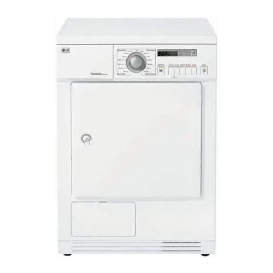
- Page 1 TRAINING MANUAL DLEC733W Dryer Training Spring 2007 Service Digital Display...
- Page 2 COMPLIANCE The responsible party for this device’s compliance is LG Electronics Alabama, Inc.; 201 James Record Road, Huntsville, AL, 35824.
-
Page 3: Table Of Contents
TABLE OF CONTENTS OVERVIEW ......................5 INTRODUCTION ....................5 SPECIFICATIONS ....................5 ACCESSORIES ....................... 6 INSTALLATION ....................... 7 LEVEL THE DRYER ....................7 POSITION THE DRYER .................... 7 CONDENSATE DRAIN ....................8 STACKING KIT ...................... 8 GROUNDING ......................8 ELECTRICAL PLUG CONNECTIONS ................9 PREPARATION OF THE DRYER .................. - Page 4 - 4 -...
-
Page 5: Overview
Series 33 (WM1333Hx, DLEC733x, etc.) laundry products are being introduced into the United States by LG Electronics during 2007. The Series 33 product line includes two dryers. This manual covers the DLEC733x condensation dryer. It is a ventless unit well suited for installation in areas where ducts to the outside can’t be installed. -
Page 6: Accessories
OVERVIEW ACCESSORIES DLEC733 1. Drain Hose Assembly 2. Dryer Rack Assembly P/No. : 5001EL2001A P/No. : 3751EL1002B 3. Stacking kit Assembly (Purchased Seperately) LGESW LGEBB P/No. : 5001EL2001C P/No. : 3300ER1012A Series 33 Dryer Training Overview... -
Page 7: Installation
INSTALLATION INSTALLATION Usually, the technician will be called to service a machine that has already been installed by someone who has been specifically trained for that task. It is important, however, that the servicer be familiar with installation procedures and able to determine whether a particular problem is a product defect or the result of poor installation. -
Page 8: Condensate Drain
< Closet-Front view > < Built in > In order to stack this dryer on an LG washing machine, a stacking kit is needed. GROUNDING This appliance must be grounded. In the event of malfunction or breakdown, grounding will reduce the risk of electric shock by providing a path of least resistance for the electric current. -
Page 9: Electrical Plug Connections
INSTALLATION Caution: Improper connection of the equipment grounding conductor can result in a risk of electric shock. Check with a qualified electrician or a service person if you are in doubt as to whether the dryer is properly grounded. ELECTRICAL PLUG CONNECTIONS Following are several warnings and instructions concerning making the electrical connection for electric dryers. - Page 10 - 10 -...
-
Page 11: Operation
OPERATION OPERATION CONTROL PANEL HIGH TEMP. / LOW TEMP. These are functioning to shorten or lengthen the cycle time by increasing or decreasing temperature. BUZZER This is about buzzer sound on/off. After power is on and you select cycle, buzzer will sound when you press a certain button on the panel. -
Page 12: Auto Cycles
OPERATION CHILD LOCK To engage the child lock, press High Temp and Low Temp buttons at the same time for about 3 seconds. A light on the display panel will come on when child lock is set. AUTO CYCLES Standard Electronic Auto Dr y Cycles Program Mixed-Fabric cycle s... -
Page 13: Troubleshooting
TROUBLESHOOTING TROUBLESHOOTING CAUTION: Be careful of electric shock or disconnecting the parts while troubleshooting. Voltage of each terminal in 220-230V~ and DC while applying an electric current. QC TEST MODE To enter the QC Test Mode, press the Power button while holding the Buzzer and Wrinkle Care buttons. -
Page 14: Wiring Diagram
TROUBLESHOOTING WIRING DIAGRAM This is a photo of the wiring diagram you will find on the back the dryer. Series 33 Dryer Training Troubleshooting... -
Page 15: Troubleshooting Chart
TROUBLESHOOTING TROUBLESHOOTING CHART Power-On Power button press LED ON Plugged in Drum not Rotating Power button Lock : No buzzer (Rotating) Start button Lock : No buzzer Door Open? Low temperature Door is not closed Replace PCB Lamp on? (" ") display Lamp broken Replace Belt... -
Page 16: Diagnostic Tests
TROUBLESHOOTING DIAGNOSTIC TESTS POWER & CONTROL PANEL Trouble Symptom : No power to the dryer or the controller Measurement condition : Power is on. [Caution] Electric shock. Please test after grounding check. Power voltage is within • Check the standard range - Circuit breaker (AC 215V~245V)? •... - Page 17 TROUBLESHOOTING DOOR SWITCH & LAMP Trouble Symptom : Malfunction of lamp operation and door switch No operation of pump motor Measurement condition : Check if they are working while being connected to power supply. Check door switch When door is opened, lamp movement.
- Page 18 TROUBLESHOOTING MOTOR Trouble Symptom : Motor malfunction, ventilation error Measurement condition : • Power cord is unplugged. • Door is closed. • Pre-Check door switch (If door switch has contact problem, pump motor is not working.) • When power is on, motor is •...
- Page 19 TROUBLESHOOTING HEATER Trouble Symptom : Heater is not working. Drying failure. The designated temperature is not reached. Measurement condition : Power cord is unplugged. With WH3,RD3 disconnected • Check and replace from Controller, controller. • Relay RTY2, RTY3 - RD3 resistance •...
- Page 20 TROUBLESHOOTING PUMP Trouble Symptom : Check if pump is out of order. "Empty Water" Error signals. Measurement condition : Power cord is unplugged. (Measure with power on) • Disassemble Pump On QC test mode, when Pump - Check foreign objects is on, - Check impeller Electric noise doesn’t occur...
- Page 21 TROUBLESHOOTING THERMISTOR Trouble Symptom : Poor drying performance(over-drying or no drying). Abnormal thermistor operation. Measurement condition : Power cord is unplugged. • Check and replace With CN1(RED4), CN4(WH4) disconnected Controller from Controller, check TH-Heater - CN4 resistance ranges table data according to surrounding temperature? TH-Drum - CN1 resistance ranges table...
- Page 22 TROUBLESHOOTING MOISTURE SENSOR Trouble Symptom : Drying Failure Measurement condition : Power cord is unplugged. • Check Harness With CN1(RED4) • Check if Sensor tips disconnected from Controller, have foreign objects - CN1 resistance is - Refer to the left picture unlimited? Metal Wire •...
-
Page 23: Component Testing
TROUBLESHOOTING COMPONENT TESTING Component Test procedure Check result Remark 1. Thermostat Measure resistance of Measure resistance by pressing Safety (Manual type) Terminal to terminal button When resistance becomes ∞ Thermostat 1) Open at 170°C (-10/+5°C) Resistance value < 5Ω 2. Thermistor Cover, Front Measure resistance of Resistance value :... - Page 24 TROUBLESHOOTING Component Test procedure Check result Remark 7. Door S/W Measure resistance of the The state that Following terminal knob is Pressed is 1) Door switch knob : open opposite to open condition Terminal : “COM”- “NC” Resistance value < 1Ω (1-3) Terminal : “COM”- “NO”...
-
Page 25: Disassembly
DISASSEMBLY DISASSEMBLY CONTROL PANEL & TOP PLATE EXPLODED VIEW : NON SVC Parts : SVC Parts A110 A100 A114 A115 A160 A113 A111 A150 A112 A120 A140 A130 Series 33 Dryer Training Disassembly... -
Page 26: Front Cabinet Exploded View
DISASSEMBLY FRONT CABINET EXPLODED VIEW Cabinet Cover & Door Assembly : NON SVC Parts B100 : SVC Parts B103 B104 B102 B101 B105 B126 B125 B127 B128 B129 B130 B133 B131 B124 B134 B140 B141 B123 B150 B122 B120 B136 B132 B121 B160... -
Page 27: Base Exploded View
DISASSEMBLY BASE EXPLODED VIEW : NON SVC Parts : SVC Parts C270 C310 C280 C290 C300 C260 C250 C141 C130 C160 C142 C150 C140 C110 C120 C230 C240 C100 C220 C210 C200 C190 C191 C180 C170 Series 33 Dryer Training Disassembly... -
Page 28: Drum Exploded View
DISASSEMBLY DRUM EXPLODED VIEW : NON SVC Parts : SVC Parts D122 D120 D100 D110 D121 JOURNAL BEARING SERVICE KIT D201 D200 D127 D150 D155 D154 D153 D230 D156 D220 D180 D190 D210 D131 D170 D161 D160 D152 D151 D157 D140 D130 Series 33 Dryer Training... -
Page 29: Service Parts List
DISASSEMBLY SERVICE PARTS LIST DLEC733W SBOM Loc No. Part No Name Loc No. Part No Name A100 3301ER1001F Plate Assembly, Top, ABS B160 3530EL1001A Grille A110 6877EL1021A Draw ing, Assembly C100 3550EL2006A Cover, Low er A111 4924EL1001A Dispenser, off w hite... -
Page 30: Disassembly Instructions
DISASSEMBLY DISASSEMBLY INSTRUCTIONS TOP PLATE 1) Disassemble top plate by unscrewing 2 screws on the rear of the dryer. 2) After pulling drawer assembly out, unscrew 1 screw. DRAWER 3) After releasing 4 hooks of control panel assembly, separate connectors from PWB assembly for disassembling control panel assembly. - Page 31 DISASSEMBLY . DOOR 4) Disassemble door assembly by unscrewing 2 screws. 5) Disassemble lower cover by releasing hook. 6) After releasing 2 levers, disassemble safety cover. . COVER, LOWER . COVER, SAFETY CASE 7) Disassemble 3 screws. 8) Disassemble the case with a Philips driver by releasing hook.
- Page 32 DISASSEMBLY CABINET COVER 10) Disassemble the cabinet cover by removing 9 screws. 11) Disassemble cabinet by unscrewing 2 at the top and 3 at the rear (left and right are the same). CABINET FRAME, BODY 12) Disassemble Body frame by unscrewing 4 screws. 13) Disassemble Harness by unscrewing 2 Earth screws and disassemble connectors.
- Page 33 DISASSEMBLY 14) Disassemble Holder and Spring by pressing down and pulling the low hook of holder. HOLDER 15) Disassemble Blower cover by unscrewing 2 screws. COVER BASE Note: Make sure that hook is properly fit after HOOK assembling Cover Base Wrong assembly will cause abnormal noise.
- Page 34 DISASSEMBLY 18) Disassemble Harness of Motor. 19) Disassemble Duct by unscrewing. DUCT Note: marked 3 screws on the lower position of Duct are only used for molding parts. Be careful of not using them for other holes. Otherwise, the holes will be expossed to water leak.
- Page 35 DISASSEMBLY 23) Disassemble Capacitor by unscrewing Nut. CAPACITOR HOUSING 24) Disassemble Heater Housing by detaching inner Connector harness and unscrewing. 25) Disassemble Heater by unscrewing 2. HEATER 26) Disassemble Frame Top by unscrewing 4 screws. FRAME (Left and right are same) 27) Unscrew 4 screws at the left and right.
- Page 36 DISASSEMBLY COVER, FRONT 28) Unscrew 1 screw at the front. 29) Disassemble Cover Front by pulling the top area out. COVER FRONT 30) Disassemble Hose from hose holder at the base. HOSE HOLDER DISPENSER 31) Disassemble Dispenser by unscrewing. Series 33 Dryer Training Disassembly...
- Page 37 DISASSEMBLY 32) Disassemble Back cover from the Base by unscrewing 2 screws. BACK COVER 33) Disassemble Drum. 34) Disassemble Drain Pump by unscrewing 2 screws. DRAIN PUMP Series 33 Dryer Training Disassembly...
- Page 40 © Copyright 2007 LG Electronics, Inc. Printed in the USA...