Table of Contents
Advertisement
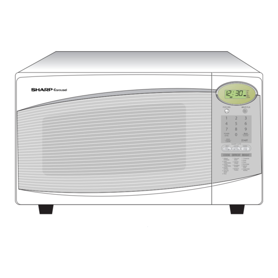
R-308JW
BEFORE SERVICING ...................................................................................................... INSIDE FRONT COVER
WARNING TO SERVICE PERSONNEL ................................................................................................................ 1
MICROWAVE MEASUREMENT PROCEDURE ................................................................................................... 2
FOREWORD AND WARNING ............................................................................................................................... 3
PRODUCT SPECIFICATIONS .............................................................................................................................. 4
GENERAL INFORMATION ................................................................................................................................... 4
OPERATION .......................................................................................................................................................... 6
TROUBLESHOOTING GUIDE .............................................................................................................................. 9
TEST PROCEDURE ............................................................................................................................................ 10
TOUCH CONTROL PANEL ................................................................................................................................. 17
COMPONENT REPLACEMENT AND ADJUSTMENT PROCEDURE ................................................................ 21
PICTORIAL DIAGRAM ........................................................................................................................................ 27
CONTROL UNIT CIRCUIT .................................................................................................................................. 28
PRINTED WIRING BOARD ................................................................................................................................. 29
PARTS LIST ........................................................................................................................................................ 30
PACKING AND ACCESSORIES ......................................................................................................................... 34
SHARP CORPORATION
SERVICE MANUAL
MODELS
In the interest of user-safety the oven should be restored to its original
condition and only parts identical to those specified should be used.
WARNING TO SERVICE PERSONNEL: Microwave ovens contain
circuitry capable of producing very high voltage and current,
contact with following parts may result in a severe, possibly fatal,
electrical shock. (High Voltage Capacitor, High Voltage Power
Transformer, Magnetron, High Voltage Rectifier Assembly, High
Voltage Harness etc..)
TABLE OF CONTENTS
This document has been published to be used for after
sales service only.
The contents are subject to change without notice.
MICROWAVE OVEN
R-308JK
R-308JS
R-308JW
R-309JW
R-308JK
R- 308JS
R-308JW
R-309JW
S2402R308JPW/
Page
Advertisement
Table of Contents

Related Manuals for Sharp R-308JK


Summary of Contents for Sharp R-308JK
-
Page 1: Table Of Contents
R-308JK R- 308JS R-308JW R-309JW SERVICE MANUAL S2402R308JPW/ MICROWAVE OVEN R-308JK MODELS R-308JS R-308JW R-309JW In the interest of user-safety the oven should be restored to its original condition and only parts identical to those specified should be used. WARNING TO SERVICE PERSONNEL: Microwave ovens contain... -
Page 2: Precautions To Be Observed Before And During Servicing To Avoid Possible Exposure To Excessive Microwave Energy
Before servicing an operative unit, perform a microwave emission check as per the Microwave Measurement Procedure outlined in this service manual. If microwave emissions level is in excess of the specified limit, contact SHARP ELECTRONICS CORPORATION immediately @1-800-237-4277. If the unit operates with the door open, service person should 1) tell the user not to operate the oven and 2) contact SHARP ELECTRONICS CORPORATION and Food and Drug Administration's Center for Devices and Radiological Health immediately. -
Page 3: Warning To Service Personnel
R-308JK R- 308JS R-308JW R-309JW WARNING TO SERVICE PERSONNEL Microwave ovens contain circuitry capable of pro- ducing very high voltage and current, contact with following parts may result in a severe, possibly fatal, electrical shock. (Example) High Voltage Capacitor, High Voltage Power Trans- former, Magnetron, High Voltage Rectifier Assem- bly, High Voltage Harness etc.. -
Page 4: Microwave Measurement Procedure
R-308JK R- 308JS R-308JW R-309JW MICROWAVE MEASUREMENT PROCEDURE A. Requirements: 1) Microwave leakage limit (Power density limit): The power density of microwave radiation emitted by a microwave oven should not exceed 1mW/cm at any point 5cm or more from the external surface of the oven, measured prior to acquisition by a... -
Page 5: Foreword And Warning
MICROWAVE OVEN R-308JK/ R-308JS/ R-308JW/ R-309JW GENERAL INFORMATION FOREWORD This Manual has been prepared to provide Sharp Electronics Corp. Service Personnel with Operation and Service Information for the SHARP MICROWAVE OVENS,R-308JK, R-308JS, R-308JW and R-309JW. OPERATION It is recommended that service personnel carefully study the entire text of this manual so that they will be qualified to render satisfactory customer service. -
Page 6: Product Specifications
R-308JK R- 308JS R-308JW R-309JW SPECIFICATION ITEM DESCRIPTION Power Requirements 120 Volts / 13.5 Amperes 60 Hertz Single phase, 3 wire grounded Power Output 1100 watts (IEC TEST PROCEDURE) Operating frequency of 2450MHz Case Dimensions Width 20-1/2" Height 12-1/4" Depth 17-3/8"... -
Page 7: Oven Diagram
R-308JK R- 308JS R-308JW R-309JW properly grounded and polarized. If the extension cord must be used, it Grounded Receptacle Box should be a 3-wire, 15 amp. or higher rated cord. Do not drape over a countertop or table where it can be pulled on by children or tripped over accidentally. -
Page 8: Operation
R-308JK R- 308JS R-308JW R-309JW OPERATION DESCRIPTION OF OPERATING SEQUENCE The following is a description of component functions during (1) When the door opens from the closed position, the primary oven operation. interlock relay (RY2) and secondary interlock switch open their contacts. - Page 9 R-308JK R- 308JS R-308JW R-309JW SCHEMATIC NOTE: CONDITION OF OVEN 1. DOOR CLOSED NOTE: " " indicates components with potential above 250V. 2. CLOCK APPEARS ON DISPLAY C/T FUSE POWER TRANSFORMER N.O. PRIMARY INTERLOCK RELAY (RY2) CAPACITOR 0.94µF CONTROL UNIT AC 2200V COM.
-
Page 10: Description And Function Of Components
R-308JK R- 308JS R-308JW R-309JW DESCRIPTION AND FUNCTION OF COMPONENTS DOOR OPEN MECHANISM INTERLOCK RELAY (RY2), SECONDARY IN- TERLOCK SWITCH AND MONITOR SWITCH The door is opened by pushing the open button on the control FOR PROPER OPERATION. (REFER TO CHAP- panel, refer to the Figure D-1. -
Page 11: Troubleshooting Guide
R-308JK R- 308JS R-308JW R-309JW TROUBLESHOOTING GUIDE Never touch any part in the circuit with your hand or an uninsulated tool while the power supply is connected. When troubleshooting the microwave oven, it is helpful to follow the Sequence of Operation in performing the checks. Many of the possible causes of trouble will require that a specific test be performed. -
Page 12: Test Procedure
R-308JK R- 308JS R-308JW R-309JW CK = Check / RE = Replace RE RE A B C D F G H RE RE CK I CK CK CK J K L M TEST PROCEDURE PROBLEM CONDITION Home fuse or circuit breaker blows... - Page 13 R-308JK R- 308JS R-308JW R-309JW TEST PROCEDURES PROCEDURE COMPONENT TEST LETTER 6. Reconnect all leads removed from components during testing. 7. Reinstall the outer case (cabinet). 8. Reconnect the power supply cord after the outer case is installed. 9. Run the oven and check all functions.
- Page 14 R-308JK R- 308JS R-308JW R-309JW TEST PROCEDURES PROCEDURE COMPONENT TEST LETTER indicated in both directions, or if an infinite resistance is read in both directions, the rectifier is probably defective and should be replaced. 5. Reconnect all leads removed from components during testing.
- Page 15 R-308JK R- 308JS R-308JW R-309JW TEST PROCEDURES PROCEDURE COMPONENT TEST LETTER switch. The meter should indicate an open circuit with the door open and a closed circuit with the door closed. If improper operation is indicated, replace the secondary interlock switch.
- Page 16 R-308JK R- 308JS R-308JW R-309JW TEST PROCEDURES PROCEDURE COMPONENT TEST LETTER 3. Discharge high voltage capacitor. 4. If the C/T fuse is blown when the door is opened, check the primary interlock relay, secondary interlock switch and monitor switch according to the "TEST PROCEDURE" for those switches before replacing the blown C/T fuse.
- Page 17 R-308JK R- 308JS R-308JW R-309JW TEST PROCEDURES PROCEDURE COMPONENT TEST LETTER 3. If the Key unit or control unit is defective. 1) Disconnect the power supply cord, and then remove outer case. 2) Open the door and block it open.
- Page 18 R-308JK R- 308JS R-308JW R-309JW TEST PROCEDURES PROCEDURE COMPONENT TEST LETTER DC. voltage indicated ....Defective relay. DC. voltage not indicated ..... Check diode which is connected to the relay coil. If diode is good, control unit is defective. RELAY SYMBOL...
-
Page 19: Touch Control Panel
R-308JK R- 308JS R-308JW R-309JW TEST PROCEDURES PROCEDURE COMPONENT TEST LETTER 2) Open the door and block it open. 3) Discharge high voltage capacitor. 4) Disconnect the leads to the primary of the power transformer. 5) Ensure that these leads remain isolated from other components and oven chassis by using insulation tape. -
Page 20: Description Of Lsi
R-308JK R- 308JS R-308JW R-309JW DESCRIPTION OF LSI The I/O signal of the LSI is detailed in the following table. Pin No. Signal Description Signal coming from touch key. When either G9 line on key matrix is touched, a corresponding signal out of P22 - P26 and P31 - P33 will be input into P50. - Page 21 R-308JK R- 308JS R-308JW R-309JW Pin No. Signal Description Oven lamp, fan motor and turntable motor driving signal 16.7 msec. To turn on and off shut off relay (RY1). The H : GND square waveform voltage is delivered to the RY1 driving circuit and RY2 control circuit.
- Page 22 R-308JK R- 308JS R-308JW R-309JW Pin No. Signal Description 0.1 sec. BZO90 Signal to sound buzzer (2.0 kHz). H : GND A: key touch sound. L : -5V B: Completion sound. 2.0 sec. H : GND L : -5V Terminal not used.
-
Page 23: Component Replacement And Adjustment Procedure
R-308JK R- 308JS R-308JW R-309JW PRECAUTIONS FOR USING LEAD-FREE SOLDER 1. Employing lead-free solder The "Main PWB" of this model employs lead-free solder. This is indicated by the "LF" symbol printed on the PWB and in the service manual. The suffix letter indicates the alloy type of the solder. - Page 24 R-308JK R- 308JS R-308JW R-309JW WARNING FOR WIRING To prevent an electric shock, take the following precau- 3) Sharp edge: tions. Bottom plate, Oven cavity, Waveguide flange and 1. Before wiring, other metallic plate. 1) Disconnect the power supply cord.
-
Page 25: Pictorial Diagram
R-308JK R- 308JS R-308JW R-309JW 7. Remove the one (1) screw holding capacitor holder to 10. Remove capacitor holder. Capacitor is now free. bottom plate. CAUTION: WHEN REPLACING HIGH VOLTAGE RECTI- 8. Remove one (1) screw holding high voltage rectifier FIER AND HIGH VOLTAGE CAPACITOR, assembly to capacitor holder. -
Page 26: Turntable Motor Removal
4. Where the corners have been snipped off bend corner 7. Now the turntable motor is free. areas flat. No sharp edges must be evident after removal of 8. After replacement use the one (1) screw to fit the turntable the turntable motor cover. - Page 27 R-308JK R- 308JS R-308JW R-309JW INSTALLATION 5. Install the fan motor to the oven cavity back plate with the 1. Install the fan blade to the fan motor shaft according to the two (2) screws. following procedure. CAUTION: 2. Hold the center of the bracket which supports the shaft of Do not hit the fan blade strongly when installed because the fan motor on the flat table.
-
Page 28: Door Replacement
R-308JK R- 308JS R-308JW R-309JW 2. The door sensing switch and secondary interlock switch 4. Reinstall outer case and check for microwave leakage interrupt the circuit before the door can be open. around door with an approved microwave survey meter. - Page 29 R-308JK R- 308JS R-308JW R-309JW...
-
Page 30: Control Unit Circuit
R-308JK R- 308JS R-308JW R-309JW... -
Page 31: Printed Wiring Board
R-308JK R- 308JS R-308JW R-309JW Figure S-3. Printed Wiring Board of Power Unit... -
Page 32: Parts List
ELECTRIC PARTS QSW-MA147WRZZ Secondary interlock switch / door sensing switch FFS-BA034WRKZ C/T fuse(150deg.C/20A) and monitor switch (D3V-1G-2C25) assembly FACCDA085WREZ Power supply cord [R-308JK, R-309JW] (Interchangeable) FACCDA103WREZ Power supply cord [R-308JW, R-308JS] (Interchangeable) FACCDA083WRE0 Power supply cord (Interchangeable) FH-DZA075WRK0 High voltage rectifier assembly [R-308JK] (Interchangeable) FH-DZA109WRKZ "... - Page 33 To have your order filled promptly and correctly, please furnish the following information. 1. MODEL NUMBER 2. REF. NO. 3. PART NO. 4. DESCRIPTION Order Parts from the authorized SHARP parts Distributor for your area. Defective parts requiring return should be returned as indicated in the Service Policy.
- Page 34 R-308JK R- 308JS R-308JW R-309JW 7-10 OVEN AND CABINET PARTS 7-10 7-10 4-15 4-12 7-12 7-11 4-16 4-13 7-10 7-10 7-10 1-11 4-14 4-12 4-17 4-10 1-10 4-12 4-11 7-10 7-10 7-10 4-12 7-10...
- Page 35 R-308JK R- 308JS R-308JW R-309JW DOOR PARTS CONTROL PANEL PARTS 3-2-1 3-2-3 MISCELLANEOUS Actual wire harness may be different from illustration. 3-2-2...
-
Page 36: Packing And Accessories
No part of this publication may be reproduced, stored in retrieval systems, or transmitted in any form or by any means, electronic, mechanical, pho- tocopying, recording, or otherwise, without prior written permission of the publisher. 2004 SHARP CORP. (2S1.700E) Printed in U.S.A...