Dell NX3600 Deployment Manual
Fluidfs nas solutions
Hide thumbs
Also See for NX3600:
- Administrator's manual (117 pages) ,
- Command line interface manual (93 pages) ,
- Owner's manual (47 pages)
Table of Contents
Advertisement
Quick Links
Advertisement
Table of Contents

Related Manuals for Dell NX3600


Summary of Contents for Dell NX3600
- Page 1 Dell FluidFS NAS Solutions NX3600/NX3610 Deployment Guide...
-
Page 2: Notes, Cautions, And Warnings
CAUTION: A CAUTION indicates either potential damage to hardware or loss of data and tells you how to avoid the problem. WARNING: A WARNING indicates a potential for property damage, personal injury, or death. © 2013 Dell Inc. Trademarks used in this text: Dell , the Dell logo, Dell Boomi , Dell Precision , OptiPlex... -
Page 3: Table Of Contents
Contents Notes, Cautions, and Warnings....................2 1 PowerVault NX3600/NX3610 NAS Appliance Overview............5 ..............................5 Supported Hardware ..............................5 Supported Software ..........................5 Other Information You May Need 2 Setting Up The Environment......................7 ..........................8 Choosing The Switch Topology ..............................9 Cabling Overview ....................10 Dedicated SAN High-Availability (Recommended) ..................11... - Page 4 Providing UNIX Identity Database Values ..........................32 Mapping Users Automatically ............................32 Creating NAS Volumes ..............................33 Creating CIFS Shares ..............................33 Creating NFS Exports ..........................33 Configuring Additional Client VIPs ............................34 Troubleshooting LUNs 6 PowerVault FluidFS NAS Setup Worksheet.................35 7 Getting Help..........................37 ...............................37 Contacting Dell ............................37 Documentation Feedback...
-
Page 5: Powervault Nx3600/Nx3610 Nas Appliance Overview
The Dell PowerVault NX3600 and NX3610 NAS appliances that work with PowerVault MD32x0i and MD36x0i iSCSI deployments help provide unified storage solutions with access to block and file data. The PowerVault NX3600 series uses the Dell Fluid File System (FluidFS) to enable both performance and capacity to scale without SAN or application downtime. - Page 6 Guide NAS cluster solution entities, such as exports, shares, volumes, and accounts. System Placemat Provides information on how to set up the hardware and install the software on your Dell FluidFS NAS solution. Resource Media Any media that ships with your system that provides documentation and tools for configuring...
-
Page 7: Setting Up The Environment
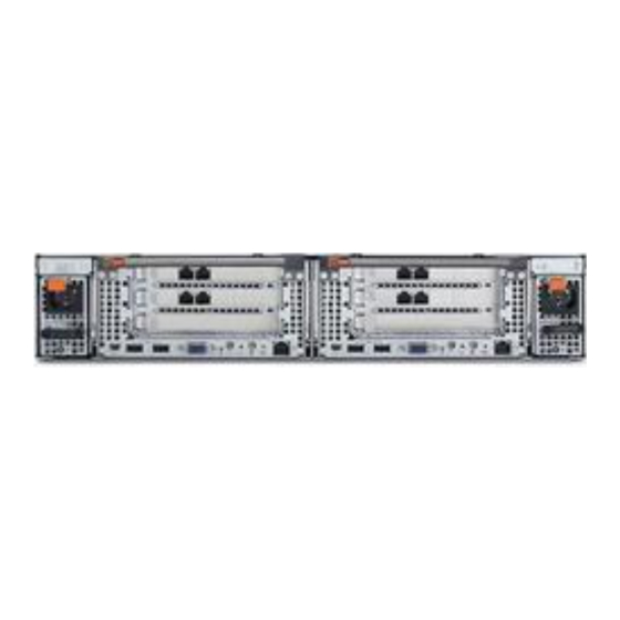
Setting Up The Environment The following are the steps required to set up your PowerVault NX3600/NX3610 NAS Appliance. For more information on each of the steps, see the relevant sections mentioned in the procedure below. Figure 1. NAS Appliance – Hardware Overview Choose the switch topology. -
Page 8: Choosing The Switch Topology
NAS Manager Configuring Wizard. Choosing The Switch Topology The PowerVault NX3600/NX3610 supports multiple switch topologies. Choose the ideal topology for your environment and cable the solution accordingly. For more information on the cabling requirements for each of the topologies, see Cabling Overview. -
Page 9: Cabling Overview
NOTE: Dell PowerConnect switches must be configured with an MTU size of 9216 or greater to accept frames of size 9000 MTU. Non-Dell switches may require a different MTU configuration for similar frame sizes. For more information on MTU configuration for non-Dell switches, see the switch-specific manual. -
Page 10: Dedicated San High-Availability (Recommended)
Figure 3. PowerVault MD Network Connections Dedicated SAN High-Availability (Recommended) It is recommended to isolate the SAN traffic from the LAN or client traffic with redundant switches for HA. All the client cables are split between the redundant client switches, and the SAN/Internal network cables are split between the redundant SAN switches. -
Page 11: Dedicated San Solution In The Non-Redundant Option
Figure 4. Dedicated SAN Solution in the High Availability Option NOTE: For more information on the details of cabling the NAS controller(s) and the MD system(s), see Cabling Overview. Dedicated SAN Solution In The Non-Redundant Option The dedicated SAN solution in the non-redundant option isolates the SAN traffic from the client traffic, but without redundant switches. -
Page 12: All-In-One High-Availability Option
Figure 5. Dedicated SAN Solution in the Non-Redundant Option NOTE: For more information on the details of cabling the NAS controller(s) and the MD system(s), see Cabling Overview. All-In-One High-Availability Option In the all-in-one high-availability option, the redundant switches are stacked and host both SAN/Internal and client network traffic. -
Page 13: All-In-One Non-Redundant Option
Figure 6. All-in-One High-Availability Option NOTE: For more information on the details of cabling the NAS controller(s) and the MD system(s), see Cabling Overview. All-In-One Non-Redundant Option In the all-in-one non-redundant option, both the SAN/Internal and client cables are connected to the same switch. CAUTION: In this configuration, the switch is a single point of failure. -
Page 14: Preparing Your Management Station
• The NAS Initial Deployment Utility (IDU) must be installed. NOTE: You can download and install the latest version of the Dell NAS IDU from dell.com/support. • The NAS cluster solution must be cabled appropriately and for the initial deployment, both the management station and NAS Appliance(s) must be connected to the same physical client or LAN switch. -
Page 15: Running Nas Idu
Follow the prompts in the installer to complete the installation. Launching NAS IDU To launch the NAS IDU, select Start → All Programs → Dell → FluidFS → NAS Deployment Utility. The NAS IDU welcome screen is displayed. NOTE: The actual configuration is not applied until all settings are confirmed in the Configuration Summary screen. - Page 16 The NAS Initial Deployment Utility screen is displayed. Click Next. The NAS Discovery screen is displayed. – All un-configured NAS appliances are displayed in the NAS Discovery screen. Select the appropriate NAS appliance model and go to step 8. – If un-configured NAS controllers are not discovered automatically, go to step 3.
- Page 17 16. Click Next. The Internal interconnect network screen is displayed. 17. If blank, enter the IP addresses for the Controllers, Winbind, and Subnet Mask. The NAS iSCSI network screen is displayed. 18. Enter the IP addresses for the following: – SAN Network A –...
-
Page 19: Setting Up Your Md Storage Solution
For additional information regarding a task such as creating virtual disks, see the PowerVault Modular x 0i/MD36x0i Owner’s Manual at dell.com/support/ Disk Storage Manager (MDSM) Help or the Dell PowerVault MD32 manuals. CAUTION: Correctly preparing the PowerVault Modular Disk (MD) storage array is critical for successfully configuring your NAS solution. -
Page 20: Enabling Jumbo Frames On The Md Storage Array
• Two of the four iSCSI host ports can be used for additional block level iSCSI access by other hosts. NOTE: The NX3600 connects to two of the four ports configured. Enabling Jumbo Frames On The MD Storage Array To enable jumbo frames on all the iSCSI ports on the MD storage array: In the PowerVault MDSM, select the Hardware tab. -
Page 21: One Disk Group (Raid 1/10), One Hot Spare
failures, with the hot spare, there can be three concurrent disk drive failures before read and write requests cannot be executed. One Disk Group (RAID 1/10), One Hot Spare Space This option consists of one RAID 1/10 disk group with two virtual disks and a single hot spare. The single RAID 1/10 disk group is made up of eleven, 2 TB hard drives. -
Page 22: Two Disk Groups (Raid 6), Zero Hot Spares
High Availability A RAID 5 disk group can continue to execute read and write requests to all its virtual disks after a single disk failure. As long as there is enough time to rebuild between failures, with hot spares, there can be three disk drive failures before read and write requests cannot be executed. -
Page 23: One Disk Group (Raid 5), One Hot Spare
One Disk Group (RAID 5), One Hot Spare CAUTION: Due to the large capacity and number of physical disks, the limitation to this option is the rebuild time. If two disks fail simultaneously, data loss may occur. Space This option consists of one RAID 5 disk group with two virtual disks and a single hot spare. The disk group is made up of eleven, 2 TB physical disks with a total size of 20 TB. -
Page 24: Creating Disk Groups Manually
It is recommended that you use the name of the NAS cluster appended by disk group and number for the disk group name. For example, NX3600-Disk-Group-0 . NOTE: The disk group name must not exceed 30 characters. In Physical Disk selection, select Automatic and click Next. -
Page 25: Creating Virtual Disks Using Powervault Mdsm
32 virtual disks and the number of virtual disks must increment in pairs. NOTE: Minimum virtual disk size is 125 GB. Although the MD allows larger virtual disks, the maximum size supported by the NX3600/NX3610 is 32 TB. For Version 10.80.x6.47 And Earlier To create virtual disks using PowerVault MDSM version 10.80.x6.47 and earlier:... -
Page 26: Creating A Host Group
For example, NOTE: Host group name must not exceed 30 alphanumeric characters. CAUTION: No host other than the NX3600/NX3610 controllers must be added to this host group. If other hosts are added to this host group, there may be data corruption. -
Page 27: Adding Virtual Disks To A Host Group
The Specify Host Port Identifiers (Define Host) screen is displayed. Select the host port identifier from the Add by selecting a known unassociated host port identifier list. Type the host name in User label and suffix the host name with IQN. Click Add. - Page 28 Click Install Certificate. The Certificate Import Wizard is displayed. Click Next. The Certificate Store screen is displayed. Verify that Automatically select the certificate store based on the type of certificate is selected and click Next. The Completing the Certificate Import Wizard screen is displayed. Click Finish.
-
Page 29: Running The Nas Manager Configuration Wizard
Running The NAS Manager Configuration Wizard The NAS Manager Configuration Wizard is the final step in completing the PowerVault NAS cluster solution configuration and integrating the solution into the environment. In addition to formatting and starting the file system, you can set up the DNS, time management, user identification, authentication parameters, and monitoring options. -
Page 30: Configuring Smtp
Configuring SMTP NOTE: It is highly recommended that you configure an SMTP server for e-mail alerts in case of issues with the cluster solution. To configure SMTP: In the Configuration Wizard (E-mail Configuration) step 3 of 14 screen, click Add SMTP server. The Configuration Wizard (Add SMTP server) step 3 of 14 is displayed. -
Page 31: Creating And Changing Admin Passwords
Click Next. The Configuration Wizard (System Stop/Start) step 6 of 14 screen is displayed. You can choose to start the file system at this time or start it later by skipping this step. The file system must be started in order to serve up files and shares. To start the file system, click Next. -
Page 32: Providing Unix Identity Database Values
Click Next. The Configuration Wizard (Identity Management Database) step 10 of 14 screen is displayed. Providing UNIX Identity Database Values The NAS solution supports NIS and LDAP for UNIX user identity management. To provide UNIX identity database values: In the Configuration Wizard (Identity Management Database) step 10 of 14 screen, select the appropriate UNIX identity database. -
Page 33: Creating Cifs Shares
Creating CIFS Shares To create CIFS shares: In the Configuration Wizard (Add CIFS Shares) step 13 of 14 screen, select the volume from the NAS Volume list to add CIFS Share. Select either General-access share or CIFS share, containing a user-based directory tree and enter the appropriate information. -
Page 34: Troubleshooting Luns
To configure additional client VIPs: Select Cluster Management → Network → Subnets. The Subnets screen displays all the available subnets. Click the Primary subnet. The Add/Edit Subnet screen is displayed. In VIP address, add additional client VIP addresses, as required. NOTE: If you need more than four VIPs, click Add VIP. -
Page 35: Powervault Fluidfs Nas Setup Worksheet
PowerVault FluidFS NAS Setup Worksheet Complete the worksheet to record the layout of your PowerVault FluidFS NAS. Use this worksheet while performing the network configuration steps in the NAS IDU. Switch Requirements Checklist Client/Primary Network SAN Network Jumbo Frames Enabled (9216 Recommended Required MTU) - Page 36 Primary Client Network MD Array 1 Controller 0, Management IP: Controller1, Management IP: Interconnect (Private) Network Select a private Class C subnet ○ 10.255.254.x ○ 172.31.254.x ○ 192.168.254.x ○___.___.___.x NAS iSCSI Network Network MTU ○ 9000 (Jumbo Frames) Subnet Mask : SAN Network A NAS Appliance 0, Controller 0 IP : NAS Appliance 1, Controller 2 IP :...
-
Page 37: Getting Help
Select the appropriate option depending on your requirement. Documentation Feedback If you have feedback for this document, write to documentation_feedback@dell.com. Alternatively, you can click on the Feedback link in any of the Dell documentation pages, fill up the form, and click Submit to send your feedback.