D-Link DGS-1510 Series Hardware Installation Manual
Gigabit ethernet smartpro switch
Hide thumbs
Also See for DGS-1510 Series:
- Reference manual (711 pages) ,
- Web ui reference manual (430 pages) ,
- Getting started manual (65 pages)
Table of Contents
Advertisement
Advertisement
Table of Contents

Related Manuals for D-Link DGS-1510 Series


Summary of Contents for D-Link DGS-1510 Series
- Page 2 Information in this document is subject to change without notice. Reproduction in any manner whatsoever, without the written permission of D-Link Corporation, is strictly forbidden. Trademarks used in this text: D-Link and the D-LINK logo are trademarks of D-Link Corporation; Microsoft and Windows are registered trademarks of Microsoft Corporation.
-
Page 3: Table Of Contents
DGS-1510 Series Gigabit Ethernet SmartPro Switch Hardware Installation Guide Table of Contents Table of Contents ................................. iii Intended Readers ................................v Typographical Conventions ............................... v Notes, Notices, and Cautions ............................v Safety Instructions ................................vi Safety Precautions ............................... vi General Precautions for Rack-Mountable Products ......................vii Protecting Against Electrostatic Discharge ........................ - Page 4 DGS-1510 Series Gigabit Ethernet SmartPro Switch Hardware Installation Guide Areas of the User Interface ............................34 Web Pages ................................. 35 Appendix A – Technical Specifications ..........................36 General .................................... 36 Physical and Environmental............................. 37 Performance..................................38 LED Indicators ................................. 38 Port Functions ..................................
-
Page 5: Intended Readers
General Precautions for Rack-Mountable Products Protecting Against Electrostatic Discharge The DGS-1510 Series Hardware Installation Guide contains information about the configuration and management of the switch. This manual is intended for network administrators familiar with network management concepts and terminology. For all practical reasons all the switches in this series will simply be referred to as the Switch throughout this manual. -
Page 6: Safety Instructions
DGS-1510 Series Gigabit Ethernet SmartPro Switch Hardware Installation Guide NOTICE: A notice indicates either potential damage to hardware or loss of data and tells you how to avoid the problem. CAUTION: A caution indicates a potential for property damage, personal injury, or death. -
Page 7: General Precautions For Rack-Mountable Products
DGS-1510 Series Gigabit Ethernet SmartPro Switch Hardware Installation Guide 115 volts (V)/60 hertz (Hz) in most of North and South America and some Far Eastern countries such as South Korea and Taiwan 100 V/50 Hz in eastern Japan and 100 V/60 Hz in western Japan 230 V/50 Hz in most of Europe, the Middle East, and the Far East •... -
Page 8: Protecting Against Electrostatic Discharge
DGS-1510 Series Gigabit Ethernet SmartPro Switch Hardware Installation Guide • Before working on the rack, make sure that the stabilizers are secured to the rack, extended to the floor, and that the full weight of the rack rests on the floor. Install front and side stabilizers on a single rack or front stabilizers for joined multiple racks before working on the rack. -
Page 9: Introduction
Switch. Package Contents When purchasing a D-Link DGS-1510 Series Switch, a list of items will be included in the package of the Switch. Open the shipping carton of the Switch and carefully unpack its contents. The carton should contain the following items: •... -
Page 10: Features
DGS-1510 Series Gigabit Ethernet SmartPro Switch Hardware Installation Guide Features The list of features below highlights the significant features of the Switch. • Supports Virtual Stacking. D-Link Single IP Management (SIM). • Supports Physical Stacking, using the SFP+ ports with 40G (Full Duplex) in topologies Linear and Ring. -
Page 11: Front-Panel Components
DGS-1510 Series Gigabit Ethernet SmartPro Switch Hardware Installation Guide • Supports Port-based Network Access Control (PNAC) better known as 802.1X. This feature includes Local and RADIUS databasis, Port-based Access Control, and MAC-based Access Control (MAC). • Supports Web-based Access Control (WAC). -
Page 12: Ports
DGS-1510 Series Gigabit Ethernet SmartPro Switch Hardware Installation Guide Figure 1–2 Front panel view of a DGS-1510-28 Switch Figure 1–3 Front panel view of a DGS-1510-28P Switch Figure 1–4 Front panel view of a DGS-1510-52 Switch Ports The Type and Number of ports available on the Switch are listed out below: •... -
Page 13: Led Indicators
DGS-1510 Series Gigabit Ethernet SmartPro Switch Hardware Installation Guide LED Indicators The Switch’s front panel presents LED indicators for Power, Console, Master (Stack Control), Stack ID and Link/Act indicators for all the ports. The DGS-1510-28P switches are equipt with an additional PoE light, to indication whether the ports are running in Power over Ethernet mode. -
Page 14: Rear Panel Components
DGS-1510 Series Gigabit Ethernet SmartPro Switch Hardware Installation Guide A separate table below describes LED indicators in more detail. Description Power This LED will light green after powering the Switch on to indicate the ready state of the device. The indicator is dark when the Switch is no longer receiving power (i.e. -
Page 15: Side Panel Components
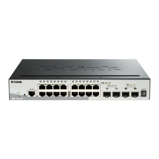
DGS-1510 Series Gigabit Ethernet SmartPro Switch Hardware Installation Guide Figure 1–9 Rear panel view of a DGS-1510-20 Switch Figure 1–10 Rear panel view of a DGS-1510-28 Switch Figure 1–11 Rear panel view of a DGS-1510-28P Switch Figure 1–12 Rear panel view of a DGS-1510-52 Switch The AC power connector is a standard three-pronged connector that supports the power cord. -
Page 16: Smart Fans
Figure 1–16 Side panels view of a DGS-1510-52 Switch Smart Fans The DGS-1510 Series Switches includes smart fans that will automatically change their speed depending on the internal temperature detected by the sensors built-in the Switch’s hardware. These smart fans support three states. They can either be off, running at a low speed, or running at a high speed. - Page 17 DGS-1510 Series Gigabit Ethernet SmartPro Switch Hardware Installation Guide DGS-1510-28P: When the internal temperature, detected by the sensor, rises above 42°C, the • fan will automatically change to the high speed. When the internal temperature, detected by the sensor, falls below 39°C, the fan will automatically change to the low speed.
-
Page 18: Installation
DGS-1510 Series Gigabit Ethernet SmartPro Switch Hardware Installation Guide 2. Installation Installation Guidelines Power On (AC Power) Installation Guidelines Please follow these guidelines for setting up the Switch: • Install the Switch on a sturdy, level surface that can support at least 3kg (6.6lb). Do not place heavy objects on the Switch. -
Page 19: Attaching Brackets To A Switch For Rack Mounting
DGS-1510 Series Gigabit Ethernet SmartPro Switch Hardware Installation Guide Attaching Brackets to a Switch for Rack Mounting The Switch is mounted to a standard 19" rack using mounting brackets. Use the following diagrams as a guide. Figure 2–2 Attach mounting brackets to the Switch Fasten the mounting brackets to the Switch using the screws provided. -
Page 20: Installing Tranceivers Into The Transceiver Ports
DGS-1510 Series Gigabit Ethernet SmartPro Switch Hardware Installation Guide CAUTION: Installing systems in a rack without the front and side stabilizers installed could cause the rack to tip over, potentially resulting in bodily injury under certain circumstances. Therefore, always install the stabilizers before installing components in the rack. After installing components in a rack, do not pull more than one component out of the rack on its slide assemblies at one time. -
Page 21: Power Failure (Ac Power)
DGS-1510 Series Gigabit Ethernet SmartPro Switch Hardware Installation Guide Power Failure (AC Power) In the event of a power failure, just as a precaution, unplug the power cord from the Switch. After the power returns, plug the power cord back into the power soket of the Switch. - Page 22 DGS-1510 Series Gigabit Ethernet SmartPro Switch Hardware Installation Guide Figure 2-7 Slide the Retainer through the Tie Wrap 4. Circle the tie of the Retainer around the power cord and into the locker of the Retainer. Figure 2-8 Circle around the power cord...
- Page 23 DGS-1510 Series Gigabit Ethernet SmartPro Switch Hardware Installation Guide Figure 2-9 Secure the power cord...
-
Page 24: Connecting The Switch
DGS-1510 Series Gigabit Ethernet SmartPro Switch Hardware Installation Guide 3. Connecting the Switch Switch to End Node Switch to another Switch Connect to a Network Backbone or Server Switch to End Node An End Node can be any networking device, plugged into any of the networking ports of the Switch, where data transmission ends. -
Page 25: Connect To A Network Backbone Or Server
DGS-1510 Series Gigabit Ethernet SmartPro Switch Hardware Installation Guide Figure 3–2 Switch to Switch Connection Connect to a Network Backbone or Server The Combo Copper/SFP ports are ideal for connecting a network backbone, server or server farm to the Switch. The copper ports operate at a speed of 10/100/1000Mbps in half-duplex or full-duplex mode. The fiber-optic ports can operate at both 100/1000Mbps in full-duplex mode. -
Page 26: Introduction To Switch Management
DGS-1510 Series Gigabit Ethernet SmartPro Switch Hardware Installation Guide 4. Introduction to Switch Management Management Options Connecting the Console Port SNMP Settings Management Options This Switch can be managed, out-of-band, through the console port on the front panel or in-band using Telnet. -
Page 27: Connecting To The Switch For The First Time
DGS-1510 Series Gigabit Ethernet SmartPro Switch Hardware Installation Guide a. The Bits per second should be 115200 baud. b. The Data bits should be 8. c. The Parity should be None. d. The Stop bits should be 1. e. The Flow control should be None. -
Page 28: Creating A User Account
DGS-1510 Series Gigabit Ethernet SmartPro Switch Hardware Installation Guide Boot Procedure V1.00.004 ------------------------------------------------------------------------------- Power On Self Test ........100 % MAC Address : 00-01-02-03-04-00 H/W Version : A1 Please Wait, Loading V1.00.010 Runtime Image ....100 % UART init .......... -
Page 29: Configuring The Ip Address
DGS-1510 Series Gigabit Ethernet SmartPro Switch Hardware Installation Guide By default, there are no user accounts configured on this Switch. To create a user account, enter the following commands. Switch> enable Switch# configure terminal Switch(config)# username nick password pass Switch(config)# username nick privilege 15... -
Page 30: Snmp Settings
DGS-1510 Series Gigabit Ethernet SmartPro Switch Hardware Installation Guide Switch> show ip interface Interface vlan1 is enabled, Link status is down IP Address is 10.90.90.90/8 (Manual) ARP timeout is 20 minutes. Proxy ARP is disabled IP Local Proxy ARP is disabled... -
Page 31: Traps
DGS-1510 Series Gigabit Ethernet SmartPro Switch Hardware Installation Guide The Switch supports SNMP versions 1, 2c, and 3. The administrator may specify which SNMP version to use to monitor and control the Switch. The three SNMP versions vary in the level of security provided between the management station and the network device. -
Page 32: D-Link Network Assistant (Dna)
NOTE: Please be sure to uninstall any existing DNA from your PC before installing the latest DNA. For detailed explanations of the DNA functions and a list of supported DDP devices, refer to the D-Link Network Assistant (DNA) User Guide. -
Page 33: Web-Based Switch Configuration
DGS-1510 Series Gigabit Ethernet SmartPro Switch Hardware Installation Guide 5. Web-based Switch Configuration Introduction Logging onto the Web Manager Web-based User Interface Introduction Most software functions of the Switch can be managed, configured, and monitored via the embedded Web-based (HTML) interface. Manage the Switch from remote stations anywhere on the network through a standard browser, such as Internet Explorer (version 5.5 and later), Mozilla Firefox (version 3 and later),... -
Page 34: Web-Based User Interface
DGS-1510 Series Gigabit Ethernet SmartPro Switch Hardware Installation Guide Web-based User Interface The user interface provides access to various Switch configuration and management windows, it allows the user to view performance statistics, and permits graphical monitoring of the system status. -
Page 35: Web Pages
DGS-1510 Series Gigabit Ethernet SmartPro Switch Hardware Installation Guide Web Pages When connecting to the management mode of the Switch with a Web browser, a login screen is displayed. Enter a user name and password to access the Switch's management mode. -
Page 36: Appendix A - Technical Specifications
DGS-1510 Series Gigabit Ethernet SmartPro Switch Hardware Installation Guide Appendix A – Technical Specifications General Feature Detailed Description Standards IEEE 802.1AB Link Layer Discovery Protocol. IEEE 802.1D-2004 Spanning Tree Protocol. IEEE 802.1p Priority Queues. IEEE 802.1Q-2005 Virtual LAN. IEEE 802.1S Multiple Spanning Tree Protocol. -
Page 37: Physical And Environmental
DGS-1510 Series Gigabit Ethernet SmartPro Switch Hardware Installation Guide Physical and Environmental Feature Detailed Description Internal Power Supply DGS-1510-20: 100-240 VAC, 50/60 Hz, 24 Watt. DGS-1510-28: 100-240 VAC, 50/60 Hz, 30 Watt. DGS-1510-28P: 100-240 VAC, 50/60 Hz, 253 Watt. DGS-1510-52: 100-240 VAC, 50/60 Hz, 54 Watt. -
Page 38: Performance
DGS-1510 Series Gigabit Ethernet SmartPro Switch Hardware Installation Guide DGS-1510-28P: 243090.6950 Hours DGS-1510-52: 433434.1606 Hours EMI/EMC; Test Reports CE Class A, FCC Class A, VCCI Report Class A, C-Tick Report Class A, BSMI, CCC Safety Certifications and UL/CSA 60950-1, IEC 60950-1:2001, BSMI... - Page 39 DGS-1510 Series Gigabit Ethernet SmartPro Switch Hardware Installation Guide Light off Power off. Console Green Solid Light Console on. Light off Console off. Green Solid Light Diagnostics pass. Normal operation. Solid Light Fan failure. Stacking ID Green Capable 1 – 6, H, h, The box ID is assigned either by user E, G.
-
Page 40: Port Functions
DGS-1510 Series Gigabit Ethernet SmartPro Switch Hardware Installation Guide transmission of data occurring at 10/100Mbps. Light off No link. PoE Mode Green Solid Light Power feeding. (Only DGS-1510-28P) Orange Solid Light Error Condition. Light Off No Power feeding. LED per SFP Port Link/Act... - Page 41 DGS-1510 Series Gigabit Ethernet SmartPro Switch Hardware Installation Guide • IEEE 802.3af compliance (DGS-1510-28P) • IEEE 802.3at compliance (DGS-1510-28P) SFP Ports Compliant with the following standards: • IEEE 802.3z compliance SFP Transceivers Supported: • DEM-302S-LX (1000BASE-LX, Single-mode, 2km) • DEM-310GT (1000BASE-LX, Single-mode, 10km) •...
- Page 42 DGS-1510 Series Gigabit Ethernet SmartPro Switch Hardware Installation Guide DDM), 20km, TX: 1270nm, RX: 1330nm) • DEM-436XT-BXD (10GBASE-LR BiDi SFP+ Transceiver (w/o DDM), 20km, TX: 1330nm, RX: 1270nm) SFP+ Direct Attached Cables (DAC) Supported: • DEM-CB100S-10-GbE (SFP+, 1m, Direct Attach Cable), for stacking.
-
Page 43: Appendix B - Cables And Connectors
DGS-1510 Series Gigabit Ethernet SmartPro Switch Hardware Installation Guide Appendix B – Cables and Connectors Ethernet Cable When connecting the Switch to another switch, a bridge or hub, a normal cable is necessary. Please review these products for matching cable pin assignment. The following diagrams and tables show the standard RJ-45 connector and their pin assignments. -
Page 44: Console Cable
DGS-1510 Series Gigabit Ethernet SmartPro Switch Hardware Installation Guide Console Cable When connecting the Switch to a PC, a Console cable is necessary. The following diagrams and tables show the standard Console-to-DJ-45 receptacle/connector and their pin assignments. Figure B–2 Console-to-RJ-45 Cable... -
Page 45: Warranties & Technical Support
The customer must submit with the product as part of the claim a written description of the Hardware defect or Software nonconformance in sufficient detail to allow D-Link to confirm the same, along with proof of purchase of the product (such as a copy of the dated purchase invoice for the product) if the product is not registered. - Page 46 D-Link Corporation/D-Link Systems, Inc., as stipulated by the United States Copyright Act of 1976 and any amendments thereto. Contents are subject to change without prior notice. Copyright 2004 by D-Link Corporation/D-Link Systems, Inc.
-
Page 47: Product Registration
Product Registration Register your D-Link product online at http://support.dlink.com/register/ Product registration is entirely voluntary and failure to complete or return this form will not diminish your warranty rights. -
Page 48: Technical Support
You can find software updates and user documentation on the D- Link website. D-Link provides free technical support for customers within the United States and within Canada for the duration of the service period, and warranty confirmation service, during the warranty period on this product. - Page 49 Technical Support United Kingdom (Mon-Fri) Home Wireless/Broadband 0871 873 3000 (9.00am–06.00pm, Sat 10.00am-02.00pm) Managed, Smart, & Wireless Switches, or Firewalls 0871 873 0909 (09.00am – 05.30pm) (BT 10ppm, other carriers may vary.) Ireland (Mon-Fri) All Products 1890 886 899 (09.00am-06.00pm, Sat 10.00am-02.00pm) €0.05ppm peak, €0.045ppm off peak Times Internet http://dlink.com...
-
Page 50: Assistance Technique
Assistance technique Assistance technique D-Link sur internet : http://dlink.com Assistance technique D-Link par téléphone : 01 76 54 84 17 Du lundi au vendredi de 9h à 19h (hors jours fériés) Asistencia Técnica Asistencia Técnica Telefónica de D-Link: +34 902 30 45 45 0,067 €/min... -
Page 51: Pomoc Techniczna
Pomoc techniczna Telefoniczna pomoc techniczna firmy D-Link: 0 801 022 021 Pomoc techniczna firmy D-Link świadczona przez Internet: http://dlink.com Technická podpora Web: http://dlink.com E-mail: support@dlink.cz Telefon ČR: +420 211 151 640 nebo SK: +421 (0)692 147 110 Telefonická podpora je v provozu: PO - PÁ od 09:00 do 17:00 Volání... - Page 52 Internetin kautta : http://dlink.com Arkisin klo. 09:00 - 18: 00 Numerosta : 0200-555 57 Teknisk Support D-Link Teknisk Support via Internet: http://dlink.com D-Link Teknisk Support via telefon: 0770-33 00 35 Vardagar 08:00 - 17:00 Assistência Técnica Assistência Técnica da D-Link na Internet: http://dlink.com e-mail: soporte@dlink.es...
- Page 53 D-Link - ovo spletno stran www.dlink.eu http://dlink.com Suport tehnic Vă mulţumim pentru alegerea produselor D-Link. Pentru mai multe informaţii, suport şi manuale ale produselor vă rugăm să vizitaţi site-ul D-Link www.dlink.eu http://dlink.com...
- Page 54 Technical Support You can find software updates and user documentation on the D-Link website. Tech Support for customers in Australia: D-Link Middle East - Dubai, U.A.E. Tel: 1300-766-868 Plot No. S31102, 24/7 Technical Support Jebel Ali Free Zone South, Web: http://www.dlink.com.au P.O.Box 18224, Dubai, U.A.E.
- Page 55 Technical Support You can find software updates and user documentation on the D-Link website. Tech Support for customers in Iran Israel המגשימים רח Unit 5, 5th Floor, No. 20, 17th Alley , Bokharest ת " פ קרית מטלון St. , Argentine Sq. , 49348 .
- Page 56 Техническая поддержка Обновления программного обеспечения и документация доступны на Интернет-сайте D-Link. D-Link предоставляет бесплатную поддержку для клиентов в течение гарантийного срока. Клиенты могут обратиться в группу технической поддержки D-Link по телефону или через Интернет. Техническая поддержка D-Link: 8-800-700-5465 Техническая поддержка через Интернет: http://www.dlink.ru...
- Page 57 SOPORTE TÉCNICO Usted puede encontrar actualizaciones de softwares o firmwares y documentación para usuarios a través de nuestro sitio www.dlinkla.com SOPORTE TÉCNICO PARA USUARIOS EN LATINO AMERICA Soporte técnico a través de los siguientes teléfonos de D-Link PAIS NUMERO Argentina...
- Page 58 Suporte Técnico Caso tenha dúvidas na instalação do produto, entre em contato com o Suporte Técnico D-Link. Acesse o site: www.dlink.com.br/suporte...
- Page 59 D-Link 友訊科技 台灣分公司 技術支援資訊 如果您還有任何本使用手冊無法協助您解決的產品相關問題,台灣 地區用戶可以透過我們的網站、電子郵件或電話等方式與D-Link台灣 地區技術支援工程師聯絡。 D-Link 免付費技術諮詢專線 0800-002-615 手機付費電話 (02)6600-0123#8715 服務時間:週一至週五,早上9:00到晚上9:00 (不含周六、日及國定假日) 網 站:http://www.dlink.com.tw 電子郵件:dssqa_service@dlink.com.tw 如果您是台灣地區以外的用戶,請參考D-Link網站全球各地 分公司的聯絡資訊以取得相關支援服務。 產品保固期限、台灣區維修據點查詢,請參考以下網頁說明: http://www.dlink.com.tw 產品維修: 使用者可直接送至全省聯強直營維修站或請洽您的原購買經銷商。...
- Page 60 Dukungan Teknis Update perangkat lunak dan dokumentasi pengguna dapat diperoleh pada situs web D-Link. Dukungan Teknis untuk pelanggan: Dukungan Teknis D-Link melalui telepon: Tel: +62-21-5731610 Dukungan Teknis D-Link melalui Internet: Email : support@dlink.co.id Website : http://support.dlink.co.id...
- Page 61 Technical Support この度は弊社製品をお買い上げいただき、誠にありがとうご ざいます。 下記弊社 Web サイトからユーザ登録及び新製品登録を 行っていただき、ダウンロードサービスにて サポート情報、ファームウェア、ユーザマニュアルを ダウンロードすることができます。 ディーリンクジャパン Web サイト URL:http://www.dlink-jp.com...
- Page 62 技术支持 辦公地址:北京市朝陽區將台路5號院5號樓 郵編:100016 技術支持中心電話:400-629-6688 技術支持中心傳真:(028)-61317620 各地維修中心地址請登陸官方網站查詢 網址:http://www.dlink.com.cn 400電話工作時間:工作日9:00-19:00;節假日9:00-18:00.
-
Page 63: Registration Card
8. What category best describes your company? Aerospace Engineering Education Finance Hospital Legal Insurance/Real Estate Manufacturing Retail/Chain store/Wholesale Government Transportation/Utilities/Communication System house/company Other________________________________ 9. Would you recommend your D-Link product to a friend? Don't know yet 10.Your comments on this product? __________________________________________________________________________________________ __________________________________________________________________________________________...