Table of Contents
Advertisement
Quick Links
Advertisement
Table of Contents

Related Manuals for GE UVD-XP3DNR(-P)


Summary of Contents for GE UVD-XP3DNR(-P)
- Page 1 Security UVD-XP3DNR(-P) Camera User Manual REV 01.00 • ISS 02SEP09...
- Page 2 Disclaimer The information in this document is subject to change without notice. GE Security, Inc. (“GE Security”) assumes no responsibility for inaccuracies or omissions and specifically disclaims any liabilities, losses, or risks, personal or otherwise, incurred as a consequence, directly or indirectly, of the use or application of any of the contents of this document.
-
Page 3: Table Of Contents
Content Preface 3 Safety terms 3 Product description 4 Features 4 User guidelines 4 Components 5 OSD control pad 6 Installation 7 Cable connection 7 Camera installation 7 Angle adjustment 7 Focus adjustment 8 Connect the monitor 8 Programming 9 Navigation 9 Main menu 9 Presets menu 10... -
Page 5: Preface
Preface This is the UVD-XP3DNR(-P) Camera. This document includes an overview of the product and detailed instructions explaining: • how to connect the camera; and • how to program the camera. • how to adjust the camera angle and focus To use this document effectively, you should have the following minimum qualifications: •... -
Page 6: Product Description
Product description The UVD-XP3DNR(-P) (rugged dome) color video cameras is a 24 VAC/12 VDC model. The cameras are equipped with a digital signal processor (DSP) for processing the video signal. Features Camera features include: • Next-generation XPosure technology. • Improved low-light performance and color balance. •... -
Page 7: Components
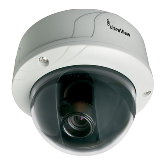
Components Figure 1 shows the main components of the rugged dome unit. Figure 1: Rugged dom2e unit Lens body Bubble Camera body OSD control pad Video monitor output Figure 3 shows the monitor output components. Figure 2: Monitor output cable A. -
Page 8: Osd Control Pad
OSD control pad The onscreen display (OSD) control pad (Figure 4) is a five-direction joystick that provides the ability to manually control the camera functions. Table 1 below lists the OSD control pad functions and describes their use. Figure 3: OSD control pad OSD control pad Table 1: OSD control pad controls Pad directions... -
Page 9: Installation
Installation This chapter provides information on how to install the camera and adjust camera angle and focus. To install the camera you will need to prepare the mounting surface, make cable connections, and mount the camera. Cable connection To make cable connections, do the following: 1. -
Page 10: Focus Adjustment
Figure 4: Camera adjustment Platform horizontal adjustment Platform vertical adjustment Rotor horizontal adjustment Focus adjustment To adjust the camera zoom and focus, see Figure 6 and do the following: 1. Loosen the zoom ring thumbscrew. 2. Turn the zoom ring to set the desired zoom. 3. -
Page 11: Programming
Programming This chapter describes how to navigate the programming menus to adjust the camera settings. Navigation To access and navigate the menus, press and hold the center of the OSD control pad (Figure 4 on page 7). Press Up or Down on the control pad to move between items, and press Enter (center of the control pad) to select the item. -
Page 12: Presets Menu
Presets menu The Presets menu options include: Normal. This is the camera default preset for general lighting conditions out of the box. This mode supports 14 bits of dynamic range and gives priority to rendering the highlights in the scene. Indoor. - Page 13 Figure 8: Camera ID setup Sync menu The SYNC option in Setup menu (Figure 8 on page 19) provides the following INT or LL (LINE LOCK) options: INT. Internal sync. Used with DC power input to reduce the phase roll of fluorescent lights.
- Page 14 Figure 10: Motion detection zone setup Motion options Off. Motion detection is disabled. Motion det. Motion detection is enabled, with default motion settings. Enter the submenu (Figure 11 below) to change the settings (see “Motion detection menu” below). When motion is detected, the word “Alarm” is displayed on the top left of the screen, and the image is zoomed, tilted, and panned to the area setup in Setup alarm zone.
- Page 15 • Digital tilt. Adjust where the camera zooms upon alarm. Move the slider to the left to tilt down, and to the right to tilt up. Setup motion zone The camera will monitor for motion in the area defined in the boxes defined in this submenu (Figure 12 below).
-
Page 16: Viewing Menu
Viewing menu The Viewing menu (Figure 14 below) provides the following options: • Flip. (OFF, HORIZ, VERT, BOTH) Turn horizontal flip off or on. • Resolution. (HIGH, NORMAL) High or normal. The High option over-sharpens the image for higher resolution. Figure 14: Viewing menu Exposure menu The Exposure menu (Figure 15 below) provides the following options:... -
Page 17: White Balance Menu
White balance menu The White balance menu (Figure 16 below) provides the following options: • Mode (ATW or PTL). ATW mode is automatic trace white balance. In PTL mode you can set a specific white balance. Figure 16: White balance menu Save/restore menu The Save/restore menu (Figure 17 below provides the following options: •... -
Page 18: Menu Map
Menu Map...