Table of Contents
Advertisement
Quick Links
Download this manual
See also:
Manual
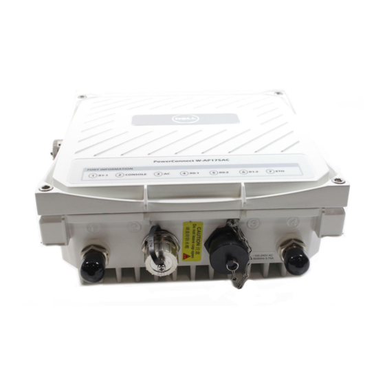
Dell PowerConnect W-AP175 Outdoor Access Point
Installation Guide
The Dell PowerConnect W-AP175 is a resilient, environmentally hardened, outdoor rated, dual-radio, dual-band
IEEE 802.11 a/b/g/n wireless access point. This outdoor access point is part of Dell's comprehensive wireless
network solution. The W-AP175 works only in conjunction with an Dell PowerConnect W-Series controller and
each AP can be centrally managed, configured, and upgraded through the controller.
NOTE: The W-AP175P requires ArubaOS 5.0.2.1 or later. The W-AP175AC and W-AP175DC require ArubaOS 6.1.2.3 or later.
There are three versions of the W-AP175, which mainly differ in the way they receive power.
W-AP175P: PoE+ powered (802.3at)
W-AP175AC: AC powered (100-240 V AC)
W-AP175DC: DC powered (12-48 V DC)
NOTE: The W-AP175AC/DC can function as a Power Sourcing Equipment (PSE) device by providing power through its ethernet
port in compliance with the IEEE 802.3af standard.
Guide Overview
"W-AP175 Hardware Overview" on page 3
models.
"Outdoor Planning and Deployment Considerations" on page 7
consider when deploying an outdoor wireless network.
"Installing Antennas" on page 11
"Weatherproofing Connections" on page 12
"Installing the W-AP175" on page 20
deployment of an W-AP175.
"Safety and Regulatory Compliance" on page 30
information.
W-AP175 Operations
Wireless access point (IEEE 802.11 a/b/g/n)
Wireless air monitor (IEEE 802.11 a/b/g/n)
Enterprise mesh point
Enterprise mesh portal
Protocol-independent networking functionality
W-AP175P: IEEE 802.3at Power over Ethernet+ (PoE+) compatible
W-AP175AC and W-AP175DC: IEEE 802.3af Power Sourcing Equipment (PSE) device
0511047-01 | January 2012
provides a detailed hardware overview of the three W-AP175
describes how to installing antennas.
provides instructions on weatherproofing the AP's connectors.
describes the multi-step process for a successful installation and
provides an overview of safety and regulatory compliance
provides key questions to ask and items to
1
Advertisement
Table of Contents

Related Manuals for Dell PowerConnect W-AP175


Summary of Contents for Dell PowerConnect W-AP175
-
Page 1: Installation Guide
The Dell PowerConnect W-AP175 is a resilient, environmentally hardened, outdoor rated, dual-radio, dual-band IEEE 802.11 a/b/g/n wireless access point. This outdoor access point is part of Dell’s comprehensive wireless network solution. The W-AP175 works only in conjunction with an Dell PowerConnect W-Series controller and each AP can be centrally managed, configured, and upgraded through the controller. -
Page 2: Package Contents
NOTE: Inform your supplier if there are any incorrect, missing, or damaged parts. If possible, retain the carton, including the original packing materials. Use these materials to repack and return the unit to the supplier if needed. Dell PowerConnect W-AP175 Outdoor Access Point | Installation Guide... -
Page 3: Antenna Interface
The interfaces are grouped into diversity pairs, one pair is marked R0 (Radio 0) and the other pair marked as R1 (Radio 1). R0 supports the 5 GHz frequency band and R1 supports the 2.4 GHz radio band. Dell PowerConnect W-AP175 Outdoor Access Point | Installation Guide... -
Page 4: Power Interface
Always remember to protect your W-AP175 by installing grounding lines. The ground connection must be complete before connecting power to the W-AP175 enclosure. Ensure that the resistance is less than 5 ohm between the ground termination point and the grounding tier. Dell PowerConnect W-AP175 Outdoor Access Point | Installation Guide... - Page 5 Each bar represents a progressive increase in (Red) signal strength, with 4 bars representing maximum signal strength (100%). Minimum data rate: One lit LEDs 25/50/75/100% Maximum data rate: Four lit LEDs Dell PowerConnect W-AP175 Outdoor Access Point | Installation Guide...
- Page 6 5 Flashes: Port overload fault 9 Flashes: Power management allocation exceeded Heat Displays the heating Unit is not in heating status status of low Blinking (Blue) Unit is pre-heating temperature Dell PowerConnect W-AP175 Outdoor Access Point | Installation Guide...
-
Page 7: Outdoor Planning And Deployment Considerations
Maximum data rate: Four lit LEDs Outdoor Planning and Deployment Considerations Prior to deploying an outdoor wireless network, the environment must be evaluated to plan for a successful Dell WLAN deployment. Successfully evaluating the environment enables the proper selection of Dell APs and antennas and assists in the determination of their placement for optimal RF coverage. -
Page 8: Identifying Known Rf Absorbers/Reflectors/Interferences Sources
Avoid any partial line of sight between the antennas Be cautious of trees or other foliage that may be near the path, or may grow and obstruct the path. Dell PowerConnect W-AP175 Outdoor Access Point | Installation Guide... -
Page 9: Antenna Height
NOTE: To avoid any obstruction along the path, the height of the object must be added to the minimum clearance required for a clear radio line of sight. Consider the following simple example, illustrated in Figure Dell PowerConnect W-AP175 Outdoor Access Point | Installation Guide... -
Page 10: Antenna Position And Orientation
Always use a channel frequency that is furthest away from another signal. If radio interference is still a problem with your wireless bridge or mesh link, changing the antenna direction may improve the situation. Dell PowerConnect W-AP175 Outdoor Access Point | Installation Guide... -
Page 11: Weather Conditions
CAUTION: A Dell Lightning Arrestor, AP-LAR-1, must be installed on each antenna port for protection against lightning induced surges. Failure to use an AP-LAR-1 can void the warranty of an Dell outdoor AP model and renders the AP susceptible to failure from lightning induced surges Rain: The wireless bridge or mesh link is weatherproofed against rain. -
Page 12: Weatherproofing Connections
7). The same materials are needed for weatherproofing both types of connections but the procedure is slightly different. For weatherproofing directly connected antennas, see “Weatherproofing Directly Connected Antennas” on page 15. For weatherproofing cable connections, see “Weatherproofing Cable Connections” on page 18. Dell PowerConnect W-AP175 Outdoor Access Point | Installation Guide... - Page 13 Figure 6 Directly Connected Antennas Weep holes Dell PowerConnect W-AP175 Outdoor Access Point | Installation Guide...
-
Page 14: Important Points To Remember
Proper weatherproofing is not a fast process. Set aside ample time to complete the steps outlined below. When wrapping, make the each layer of tape as flat as possible. Wrinkles and folds in the tape create places for water and moisture to gather. Dell PowerConnect W-AP175 Outdoor Access Point | Installation Guide... - Page 15 5. Repeat steps 3 and 4 until the wrapping extends all the way to the AP’s case. Figure 8 First Wrapping of Tape Pieces of tape as needed Wrap tape from just above knurled section to base of antenna mount Leave weep holes uncovered Dell PowerConnect W-AP175 Outdoor Access Point | Installation Guide...
- Page 16 Figure 10 Butyl Rubber Wrap Wrap rubber around base Squeeze to of antenna bond rubber mount to itself Rubber will be wrapped with 4 layers of tape Dell PowerConnect W-AP175 Outdoor Access Point | Installation Guide...
- Page 17 Rubber will be wrapped with 4 layers of tape First and third layers wrap Second and final layers wrap top to bottom bottom to top 4. Repeat this process for all connectors. Dell PowerConnect W-AP175 Outdoor Access Point | Installation Guide...
-
Page 18: Weatherproofing Cable Connections
4. Repeat steps 3 and 4 until the wrapping extends all the way to the cable’s insulation. Figure 12 First Wrapping of Tape Wrap tape from antenna connector base to cable Pieces of tape as needed Dell PowerConnect W-AP175 Outdoor Access Point | Installation Guide... - Page 19 Stretch thinner & wider Figure 14 Butyl Rubber Wrap Squeeze to Rubber will bond rubber be wrapped to itself with 4 layers of tape Wrap rubber around connector and cable Dell PowerConnect W-AP175 Outdoor Access Point | Installation Guide...
-
Page 20: Selecting The Installation Site
In engineering design, the site should be selected according to the network planning and technical requirements of communications equipment, as well as the considerations such as climate, hydrology, geology, earthquake, electric power, and transportation. Dell PowerConnect W-AP175 Outdoor Access Point | Installation Guide... - Page 21 2. Attach the mounting bracket (with W-AP175) on the pole using four M8 x110 bolts (with flat washers, spring washers and nuts) and the pair of pole anchors. Figure 17 Attaching the mounting bracket to the pole Dell PowerConnect W-AP175 Outdoor Access Point | Installation Guide...
- Page 22 Adjust the position of the mounting bracket and tighten the expansion screws. 5. Attach the W-AP175 to the mounting bracket by inserting the two M6 x30 bolts (with flat and spring washers) through the installation holes, and tighten the bolts. Dell PowerConnect W-AP175 Outdoor Access Point | Installation Guide...
- Page 23 2. Fasten the copper lug to the grounding hole on the W-AP175 with the M4 x12 bolt and external-tooth washer. Dell PowerConnect W-AP175 Outdoor Access Point | Installation Guide...
- Page 24 9. Slide the sealing nut over the narrow end of the weatherproof connector socket and hand tighten it. 10. Insert the ethernet cable connector into the ethernet interface and hand-tighten the locknut. 11. Water-proof the ethernet cable connection with electrical tape and butyl rubber. Dell PowerConnect W-AP175 Outdoor Access Point | Installation Guide...
- Page 25 13. Thread the sealing nut onto the sealing bolt. 14. Insert the ethernet cable connector into the ethernet interface and hand-tighten the locknut. 15. Water-proof the ethernet cable connection with electrical tape and butyl rubber. Dell PowerConnect W-AP175 Outdoor Access Point | Installation Guide...
- Page 26 NOTE: The W-AP175 does not ship with any power cables; these are available as accessories and should be ordered separately. In addition to completed power cables, Dell also offers an outdoor rated AC and DC connector kit that can be used to connect a compatible power cable to the W-AP175.
- Page 27 Attaching the Solar Shield to the W-AP175 Attach the solar shield to the W-AP175 by using the four M4 x16 (with flat and spring washers). Figure 24 Attaching the Solar Shield to the AP Dell PowerConnect W-AP175 Outdoor Access Point | Installation Guide...
-
Page 28: Product Specifications
Power: 1 x DC power connector (in W-AP175DC model only) 1 x AC power connector (in W-AP175AC model only) Antenna: 4 x N-Type female antenna interfaces Dell PowerConnect W-AP175 Outdoor Access Point | Installation Guide... -
Page 29: Wireless Lan
802.11a/g: 6, 9, 12, 18, 24, 36, 48, 54 802.11n: MCS0 - MCS15 (6.5 Mbps to 300 Mbps) 802.11n high-throughput (HT) support: HT 20/40 802.11n packet aggregation: A-MPDU, A-MSDU Dell PowerConnect W-AP175 Outdoor Access Point | Installation Guide... -
Page 30: Safety And Regulatory Compliance
Mobile Satellite Systems. CAUTION: Dell Access Points and the AP-LAR-1 lightning arrestor are required to be installed by a professional installer. The professional installer is responsible for ensuring that grounding is available and it meets applicable local and national electrical codes. -
Page 31: Proper Disposal Of Dell Equipment
For the most current information about Global Environmental Compliance and Dell products, see dell.com. Waste of Electrical and Electronic Equipment Dell products at end of life are subject to separate collection and treatment in the EU Member States, Norway, and Switzerland and therefore are marked with the symbol shown at the left (crossed-out wheelie bin). -
Page 32: Contacting Support
® Edge Company logo, and Aruba Mobility Management System . Dell™, the DELL™ logo, and PowerConnect™ are trademarks of Dell Inc. All rights reserved. Specifications in this manual are subject to change without notice. Originated in the USA. All other trademarks are the property of their respective owners.