Table of Contents
Advertisement
Advertisement
Table of Contents

Related Manuals for Asus CROSSHAIR III FORMULA - Republic of Gamers Series Motherboard


Summary of Contents for Asus CROSSHAIR III FORMULA - Republic of Gamers Series Motherboard
- Page 1 Crosshair III Formula...
- Page 2 Product warranty or service will not be extended if: (1) the product is repaired, modified or altered, unless such repair, modification of alteration is authorized in writing by ASUS; or (2) the serial number of the product is defaced or missing.
-
Page 3: Table Of Contents
Product highlights ............1-2 1.3.2 ROG Intelligent Performance & Overclocking features ... 1-3 1.3.3 ROG unique features ............1-5 1.3.4 ASUS special features ............ 1-6 Chapter 2: Hardware information Before you proceed ..............2-1 Motherboard overview ..............2-6 2.2.1 Motherboard layout ............2-6 2.2.2... - Page 4 BIOS setup Managing and updating your BIOS ..........3-1 3.1.1 ASUS Update utility ............3-1 3.1.2 ASUS EZ Flash 2 utility ........... 3-4 3.1.3 ASUS CrashFree BIOS 3 utility ........3-5 BIOS setup program ..............3-6 3.2.1 BIOS menu screen ............3-7 3.2.2...
- Page 5 Contents 3.3.5 CPU Ratio [Auto] ............3-10 3.3.6 CPU Configuration ............3-10 3.3.7 DRAM Frequency [Auto] ..........3-10 3.3.8 DDR3 Memory Profile [Disabled] ........3-10 3.3.9 CPU/NB Frequency [Auto] ..........3-11 3.3.10 HT Link Speed [Auto] .............3-11 3.3.11 DRAM Controller configuration ........3-11 3.3.12 DRAM Timing/Driving Config.
- Page 6 Boot Device Priority ............3-39 3.7.2 Boot Settings Configuration .......... 3-40 3.7.3 Security ................. 3-41 Tools menu ................. 3-43 3.8.1 ASUS EZ Flash 2 ............3-43 3.8.2 ASUS O.C. Profile ............3-44 3.8.3 TweakIt Batch File ............3-45 3.8.4 AI NET 2................ 3-46 Exit menu ..................
- Page 7 Contents 4.3.1 ASUS MyLogo3™ ............4-9 4.3.2 Sound Blaster X-Fi audio utility ........4-11 4.3.3 ASUS PC Probe II ............4-15 4.3.4 ASUS AI Suite ............... 4-21 4.3.5 ASUS Q-Fan 2 .............. 4-23 4.3.6 CPU Level Up ............... 4-24 4.3.7 ASUS TurboV ..............4-25 RAID configurations ..............
-
Page 8: Notices
Canadian Department of Communications. This class B digital apparatus complies with Canadian ICES-003. REACH Complying with the REACH (Registration, Evaluation, Authorization, and Restriction of Chemicals) regulatory framework, we published the chemical substances in our products at ASUS website at http://green.asus.com/english/ REACH.htm. viii... -
Page 9: Safety Information
Safety information Electrical safety • To prevent electrical shock hazard, disconnect the power cable from the electrical outlet before relocating the system. • When adding or removing devices to or from the system, ensure that the power cables for the devices are unplugged before the signal cables are connected. If possible, disconnect all power cables from the existing system before you add a device. - Page 10 Operation safety • Before installing the motherboard and adding devices on it, carefully read all the manuals that came with the package. • Before using the product, ensure all cables are correctly connected and the power cables are not damaged. If you detect any damage, contact your dealer immediately.
-
Page 11: About This Guide
Refer to the following sources for additional information and for product and software updates. ASUS websites The ASUS website provides updated information on ASUS hardware and software products. Refer to the ASUS contact information. Optional documentation Your product package may include optional documentation, such as warranty flyers, that may have been added by your dealer. -
Page 12: Conventions Used In This Guide
Conventions used in this guide To ensure that you perform certain tasks properly, take note of the following symbols used throughout this manual. DANGER/WARNING: Information to prevent injury to yourself when trying to complete a task. CAUTION: Information to prevent damage to the components when trying to complete a task. -
Page 13: Crosshair Iii Formula Specifications Summary
MHz, ECC and non�ECC, un�buffered memory MHz, ECC and non�ECC, un�buffered memory memory memory *Refer to www.asus.com or user manual for the Memory QVL (Qualified Vendors Lists) **Due to OS limitation, when installing total memory of 4GB capacity or more, Windows 32-bit operation ®... - Page 14 Intelligent overclocking tools: - ASUS TurboV � O.C Profile Overclocking Protection: - COP EX (Component Overheat Protection - EX) - Voltiminder LED - ASUS C.P.R.(CPU Parameter Recall) Other Special Features External LCD Poster ASUS Q-Connector ASUS Q-Shield ASUS Q-Fan 2...
- Page 15 24-pin ATX Power connector 8-pin ATX 12V Power connector System panel connector Software Support DVD: - Drivers and applications * ASUS PC Probe II * ASUS Update * ASUS AI Suite * AMD OverDrive Utility (AOD) * Sound Blaster X-Fi Utility * Futuremark...
-
Page 17: Chapter 1: Product Introduction
This chapter describes the motherboard features and the new technologies it supports. Chapter 1: Product introduction... - Page 18 Chapter summary Welcome! ..................1-1 Package contents ................. 1-1 Special features ................1-2 ROG Crosshair III Formula...
-
Page 19: Welcome
Thank you for buying an ROG Crosshair III Formula motherboard! The motherboard delivers a host of new features and latest technologies, making it another standout in the long line of ASUS quality motherboards! Before you start installing the motherboard, and hardware devices on it, check the items in your package with the list below. -
Page 20: Special Features
Green ASUS This motherboard and its packaging comply with the European Union’s Restriction on the use of Hazardous Substances (RoHS). This is in line with the ASUS vision of creating environment-friendly and recyclable products/packaging to safeguard consumers’ health while minimizing the impact on the environment. -
Page 21: Rog Intelligent Performance & Overclocking Features
DDR3 1600 (O.C.) support This motherboard supports DDR3 1600(O.C.) that provides faster data transfer rate and more bandwith to increase memory computing efficiency, enhancing system performance in 3D graphics and other memory demanding applications PCIe 2.0 Double Speed; Double Bandwidth This motherboard supports the latest PCIe 2.0 device for double speed and bandwidth which enhances system performance. -
Page 22: Voltiminder Led
MemOK! Any memory is A-OK! Memory compatibility is among the top concerns when it comes to computer upgrades. Worry no more, MemOK! is the fastest memory booting solution today. This remarkable memory rescue tool requires nothing but a push of a button to patch memory issues and get you system up and running in no time. -
Page 23: Rog Unique Features
Q-Fan2 ASUS Q-Fan2 technology intelligently adjusts both CPU fan and chassis fan speeds according to system loading to ensure quiet, cool and efficient operation. ROG Crosshair III Formula... -
Page 24: Asus Special Features
1.3.4 ASUS special features ASUS EZ DIY ASUS EZ DIY feature collection provides you easy ways to install computer components, update the BIOS or back up your favorite settings. ASUS Q-Shield The specially designed ASUS Q�Shield does without the usual “fingers”—... - Page 25 TurboV Feel the adrenaline rush of real�time OC—now a reality with the ASUS TurboV. This easy OC tool allows you to overclock without exiting or rebooting the OS; and its user-friendly interface makes overclock with just a few clicks away. Moreover, the ASUS OC profiles in TurboV provides the best O.C.
- Page 26 Chapter 1: Product Introduction...
-
Page 27: Chapter 2: Hardware Information
This chapter lists the hardware setup procedures that you have to perform when installing system components. It includes description of the jumpers and Chapter 2: Hardware connectors on the motherboard. information... - Page 28 Chapter summary Before you proceed ..............2-1 Motherboard overview ..............2-6 Central Processing Unit (CPU) ........... 2-9 System memory ................. 2-14 Expansion slots ................2-21 Jumper ..................2-25 I/O shield, LCD Poster and Audio card Installation ....2-26 Connectors ................. 2-28 Starting up for the first time ............
-
Page 29: Before You Proceed
Before you proceed Take note of the following precautions before you install motherboard components or change any motherboard settings. • Unplug the power cord from the wall socket before touching any component. • Use a grounded wrist strap or touch a safely grounded object or a metal object, such as the power supply case, before handling components to avoid damaging them due to static electricity. -
Page 30: Onboard Leds
Onboard LEDs The motherboard comes with LEDs that indicate the voltage conditions of CPU, memory, northbridge, and southbridge. You may adjust the voltages in BIOS. There are also an LED for hard disk drive activity and an onboard switch for power status. For more information about voltage adjustment, refer to 3.3 Extreme Tweaker menu. - Page 31 Northbridge/Southbridge LEDs The northbridge and southbridge LEDs each have two different voltage displays. The northbridge LED displays either the NB Voltage or the NB 1.8 Voltage. The southbridge LED shows either the SB Voltage, SB 1.2V Voltage, or the HT. You can select the voltage to display in BIOS. Refer to the illustration below for the location of the northbridge/southbridge LEDs and the table below for LED definition.
- Page 32 Memory LED Refer to the illustration below for the location of the memory LED and the table below for LED definition. Normal (green) High (yellow) Crazy (red) DRAM Bus Voltage 1.51050–1.72250 1.73575–2.31875 2.33200–2.80900 Hard Disk LED The hard disk LED is designed to indicate the hard disk activity. It blinks when data is being written into or read from the hard disk drive.
- Page 33 Power LED The motherboard comes with a power-on switch that lights up to indicate that the system is ON, in sleep mode, or in soft-off mode. This is a reminder that you should shut down the system and unplug the power cable before removing or plugging in any motherboard component.
-
Page 34: Motherboard Overview
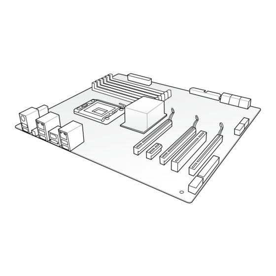
Motherboard overview 2.2.1 Motherboard layout Chapter 2: Hardware information... -
Page 35: Supremefx X-Fi Audio Card Layout
2.2.2 SupremeFX X-Fi audio card layout 2.2.3 Layout contents Connectors/Jumpers/Switches/Slots Page CPU, chassis, and optional fan connectors (4�pin CPU_FAN; 2-35 4�pin PWR_FAN; 4�pin CHA_FAN1–2; 4�pin OPT_FAN1–3) ATX power connectors (24-pin EATXPWR, 8-pin EATX12V) 2-37 AM3 Socket ® DDR3 DIMM slots 2-14 IDE connector (40-1 pin PRI_IDE) 2-30... -
Page 36: Placement Direction
2.2.4 Placement direction When installing the motherboard, ensure that you place it into the chassis in the correct orientation. The edge with external ports goes to the rear part of the chassis as indicated in the image below. 2.2.5 Screw holes Place nine (9) screws into the holes indicated by circles to secure the motherboard to the chassis. -
Page 37: Central Processing Unit (Cpu)
Central Processing Unit (CPU) The motherboard comes with an AMD AM3 Socket for AMD socket AM3 ® Phenom™ II / Athlon™ II / Sempron™ 100 Series processors. The AM3 socket has a different pinout from the AM2+/AM2 socket. Ensure you use a CPU designed for the AM3 socket. The CPU fits in only one correct orientation. - Page 38 Position the CPU above the socket such that the CPU corner with the gold triangle matches the socket corner with a small triangle. Carefully insert the CPU into the socket until it fits in place. Gold triangle Small triangle When the CPU is in place, push down the socket lever to secure the CPU.
-
Page 39: Installing The Heatsink And Fan
2.3.2 Installing the heatsink and fan The AMD socket AM3 Phenom™ II / Athlon™ II / Sempron™ 100 Series processors requires a specially designed heatsink and fan assembly to ensure optimum thermal condition and performance. Ensure that you use only AMD�certified heatsink and fan assembly. To install the CPU heatsink and fan: Place the heatsink on top of the installed CPU, ensuring that the heatsink fits properly on the retention module base. - Page 40 Attach one end of the retention bracket to the retention module base. Align the other end of the retention bracket to the retention module base. A clicking sound denotes that the retention bracket is in place. Ensure that the fan and heatsink assembly perfectly fits the retention mechanism module base, otherwise you cannot snap...
- Page 41 When the fan and heatsink assembly is in place, connect the CPU fan cable to the connector on the motherboard labeled CPU_FAN. • DO NOT forget to connect the CPU fan connector! Hardware monitoring errors can occur if you fail to plug this connector. •...
-
Page 42: System Memory
System memory 2.4.1 Overview The motherboard comes with four Double Data Rate 3 (DDR3) Dual Inline Memory Modules (DIMM) sockets. A DDR3 module has the same physical dimensions as a DDR2 DIMM but is notched differently to prevent installation on a DDR2 DIMM socket. DDR3 modules are developed for better performance with less power consumption. -
Page 43: Recommended Memory Configurations
Recommended memory configurations One DIMM: You may install one memory module in any slot as a single-channel operation. Two DIMMs (dual-channel operation): Four DIMMs (dual-channel operation): ROG Crosshair III Formula 2-15... -
Page 44: Memory Configurations
2.4.2 Memory configurations You may install 512 MB, 1 GB, 2 GB and 4 GB unbuffered ECC and non-ECC DDR3 DIMMs into the DIMM sockets. • You may install varying memory sizes in Channel A and Channel B. The system maps the total size of the lower�sized channel for the dual�channel configuration. - Page 45 Crosshair III Formula Motherboard Qualified Vendors Lists (QVL) DDR������MH�� capability 3-1600MHz capability -1600MHz capability Vendor Part No. Size Chip Chip NO. Timing Voltage DIMM Brand Dimm(Bios) socket support (Optional) A* B* C* A-DATA AD31600E001GMU 3072MB Heat-Sink Package 8-8-8-24 1.65-1.85 • •...
- Page 46 • • Asint SLY3128M8-EDJ 1024MB SS Asint DDRIII1208-DJ (9-9-9-24) • Asint SLZ3128M8-EDJ 2048MB DS Asint DDRIII1208-DJ (9-9-9-24) • • ASUS 1024MB DS N/A Heat-Sink Package (1333-9-9-9-24) • • BUFFALO FSX1333D3G-2G 2048MB DS N/A Heat-Sink Package (1066-7-7-7-20) • • Elixir M2F2G64CB8HA4N-CG...
- Page 47 • C*: Supports four modules inserted into both the yellow and black slots as two pairs of dual�channel memory configuration. Visit the ASUS website at www.asus.com for the latest QVL. ROG Crosshair III Formula 2-19...
-
Page 48: Installing A Dimm
2.4.3 Installing a DIMM Ensure to unplug the power supply before adding or removing DIMMs or other system components. Failure to do so may cause severe damage to both the motherboard and the components. To install a DIMM DIMM notch Unlock a DIMM socket by pressing the retaining clips outward. -
Page 49: Expansion Slots
Expansion slots In the future, you may need to install expansion cards. The following sub-sections describe the slots and the expansion cards that they support. Ensure to unplug the power cord before adding or removing expansion cards. Failure to do so may cause you physical injury and damage motherboard components. -
Page 50: Interrupt Assignments
2.5.3 Interrupt assignments Standard interrupt assignments Priority Standard function System Timer Keyboard Controller – Redirect to IRQ#9 Communications Port (COM1)* IRQ Holder for PCI Steering* Reserved Reserved System CMOS/Real Time Clock IRQ Holder for PCI Steering* IRQ Holder for PCI Steering* IRQ Holder for PCI Steering* Reserved Numeric Data Processor... -
Page 51: Pci Slot
2.5.4 PCI slot The PCI slot supports cards such as a LAN card, SCSI card, USB card, and other cards that comply with PCI specifications. Refer to the figure below for the location of the slot. 2.5.5 PCI Express x1 slots This motherboard supports PCI Express x1 network cards, SCSI cards and other cards that comply with the PCI Express specifications. - Page 52 • In single VGA card mode, use first the PCIe 2.0 x16_1 slot for a PCI Express x16 graphics card to get better performance. • In CrossFireX™ mode, use the PCIe 2.0 x16_1 and PCIe 2.0 x16_2 (blue) slots for PCI Express x16 graphics cards to get better performance.
-
Page 53: Jumper
Jumper Clear RTC RAM (3-pin CLRTC_SW) This jumper allows you to enable the clr CMOS switch on the back I/O. You can clear the CMOS memory and system setup parameters by erasing the CMOS RTC RAM data. The clr CMOS switch on the back I/O helps you easily clear the system setup information such as system passwords. -
Page 54: I/O Shield, Lcd Poster And Audio Card Installation
I/O shield, LCD Poster and Audio card Installation 2.7.1 I/O shield and LCD Poster Installation Orient the motherboard and install Install the I/O shield to the chassis it to the chassis. Make sure that the by snapping it in place from inside. motherboard external ports fit the I/O openings. -
Page 55: Audio Card Installation
2.7.2 Audio card Installation Take out the Audio card from the package. Locate the audio slot on the motherboard. Align the card connector with the slot and press firmly until the card sits on the slot completely. The photo below shows the audio card installed on the motherboard. -
Page 56: Connectors
Connectors 2.8.1 Rear panel connectors Rear panel connectors 1. PS/2 keyboard port (purple) 6. IEEE 1394a port 2. LAN (RJ-45) port* 7. External SATA port 3. USB 2.0 ports 5 and 6 8. USB 2.0 ports 1 and 2 4. Clear CMOS switch 9. -
Page 57: Lan Port Led Indications
* LAN port LED indications Activity/ Speed Speed LED Activity/Link Description Link LED Soft-off Mode Yellow Blinking During Power ON/OFF Yellow Blinking ORANGE 100 Mbps connection LAN port Yellow Blinking GREEN 1 Gbps connection **Audio 2, 4, �, or 8�channel configuration Headset Port 4-channel... -
Page 58: Internal Connectors
2.7.2 Internal connectors IDE connector (40-1 pin PRI_IDE) The onboard IDE connector is for the Ultra DMA 133/100/66 signal cable. There are three connectors on each Ultra DMA 133/100/66 signal cable: blue, black, and gray. Connect the blue connector to the motherboard’s IDE connector, then select one of the following modes to configure your device. - Page 59 ® SB750 Southbridge Serial ATA connectors (7-pin SATA1–5) These connectors are for the Serial ATA signal cables for Serial ATA hard disk and optical disk drives. If you install SATA hard disk drives to the SATA1–5 connectors, you can create a RAID 0, RAID 1, RAID 5, RAID 10 or JBOD configuration through ®...
- Page 60 480 Mbps connection speed. Never connect a 1394 cable to the USB connectors. Doing so will damage the motherboard! You can connect the USB cable to ASUS Q�Connector (USB, blue) first, and then install the Q-Connector (USB) to the USB connector onboard. 2-32...
- Page 61 IEEE 1394a port connector (10-1 pin IE1394_2) This connector is for an IEEE 1394a port. Connect the IEEE 1394a module cable to this connector, then install the module to a slot opening at the back of the system chassis. Never connect a USB cable to the IEEE 1394a connector. Doing so will damage the motherboard! ROG connector (3-pin ROG) This connector is for the box (labeled as Republic of Gamers) on the...
- Page 62 GP connector (8-pin GP) This connector is for ASUS OC Station connection only. Connect one end Connect one end of the supplied data cable to the GP connector on the OC Station and the other end to this connector and USB78 on the motherboard to enjoy easier overclocking.
- Page 63 CPU, chassis, and optional fan connectors (4-pin CPU_FAN, 4-pin PWR_FAN, 4-pin CHA_FAN1–3, 4-pin OPT_FAN1–3) The fan connectors support cooling fans of 350 mA–2000 mA (24 W max.) or a total of 1 A–7 A (84 W max.) at +12V. Connect the fan cables to the fan connectors on the motherboard, ensuring that the black wire of each cable matches the ground pin of the connector.
- Page 64 Thermal sensor cable connectors (2-pin OPT_TEMP1/2/3) These connectors are for temperature monitoring. Connect the thermal sensor cables to these connectors and place the other ends to the devices which you want to monitor temperature. The optional fan1/2/3 can work with the temperature sensors for a better cooling effect.
-
Page 65: Atx Power Connectors
• If you are uncertain about the minimum power supply requirement for your system, refer to the Recommended Power Supply Wattage Calculator at http://support.asus.com/PowerSupplyCalculator/PSCalculator. aspx?SLanguage=en-us for details. ROG Crosshair III Formula 2-37... - Page 66 10. System panel connector (20-8 pin PANEL) This connector supports several chassis-mounted functions. • System power LED (2-pin PLED) This 2-pin connector is for the system power LED. Connect the chassis power LED cable to this connector. The system power LED lights up when you turn on the system power, and blinks when the system is in sleep mode.
-
Page 67: Audio Connectors
11. Audio connectors Optical drive audio connector: This connector allows you to receive stereo This connector allows you to receive stereo allows you to receive stereo audio input from sound sources such as a CD-ROM, TV tuner, or MPEG card. Front panel audio connector: This connector is for a chassis-mounted front panel audio I/O module that supports either HD Audio or legacy AC`97 audio standard. - Page 68 12. ASUS Q-Connector (system panel) Use the ASUS Q-Connector to connect/disconnect the chassis front panel cables. To install the ASUS Q-Connector: Connect the front panel cables to the ASUS Q-Connector. Refer to the labels on the Q- Connector to know the detailed pin...
-
Page 69: Onboard Switches
2.8.3 Onboard switches Onboard switches allow you to fine�tune performance when working on a bare or open-case system. This is ideal for overclockers and gamers who continually change settings to enhance system performance. Power-on switch Press the power-on switch to wake/power up the system. Reset switch Press the reset switch to reboot the system. - Page 70 MemOK! switch Press the MemOK! switch to load failsafe settings for memory compatibility and improving system boot success. 2-42 Chapter 2: Hardware information...
-
Page 71: Starting Up For The First Time
Starting up for the first time After making all the connections, replace the system case cover. Be sure that all switches are off. Connect the power cord to the power connector at the back of the system chassis. Connect the power cord to a power outlet that is equipped with a surge protector. -
Page 72: 2.10 Turning Off The Computer
2.10 Turning off the computer 2.10.1 Using the OS shut down function If you are using Windows Vista™: ® Click the Start button then select Shut Down. The power supply should turn off after Windows shuts down. ® If you are using Windows ®... -
Page 73: Chapter 3: Bios Setup
This chapter tells how to change the system settings through the BIOS Setup menus. Detailed descriptions of the BIOS parameters are also provided. BIOS setup... - Page 74 Chapter summary Managing and updating your BIOS ..........3-1 BIOS setup program ..............3-6 Extreme Tweaker menu ............... 3-9 Main menu .................. 3-18 Advanced menu ................. 3-23 Power menu ................3-33 Boot menu .................. 3-39 Tools menu ................. 3-43 Exit menu ..................3-47 ROG Crosshair III Formula...
-
Page 75: Managing And Updating Your Bios
® ASUS EZ Flash 2 (Updates the BIOS using a floppy disk or USB flash disk.) ASUS CrashFree BIOS 3 utility: Restores the BIOS using the motherboard support DVD or a USB flash drive when the BIOS file fails or gets corrupted. - Page 76 To update the BIOS through the Internet: Launch the ASUS Update utility from the Windows desktop by clicking Start ® > Programs > ASUS > ASUSUpdate > ASUSUpdate. The ASUS Update main window appears. Select Update BIOS from the Select the ASUS FTP site nearest...
- Page 77 To update the BIOS through a BIOS file: Launch the ASUS Update utility from the Windows desktop by clicking Start ® > Programs > ASUS > ASUSUpdate > ASUSUpdate. The ASUS Update main window appears. Select Update BIOS from a file option from the drop-down menu, then click Next.
-
Page 78: Asus Ez Flash 2 Utility
3.1.2 ASUS EZ Flash 2 utility The ASUS EZ Flash 2 feature allows you to update the BIOS without having to use a DOS-based utility. The EZ Flash 2 utility is built in the BIOS chip so it is accessible by pressing <Alt> + <F2> during the Power-On Self Tests (POST). -
Page 79: Asus Crashfree Bios 3 Utility
3.1.3 ASUS CrashFree BIOS 3 utility The ASUS CrashFree BIOS 3 utility is an auto recovery tool that allows you to restore the BIOS file when it fails or gets corrupted during the updating process. You can restore a corrupted BIOS file using the motherboard support DVD or a USB flash drive that contains the BIOS file. -
Page 80: Bios Setup Program
The BIOS setup screens shown in this section are for reference purposes only, and may not exactly match what you see on your screen. • Visit the ASUS website at www.asus.com to download the latest BIOS file for this motherboard. Chapter 3: BIOS setup... -
Page 81: Bios Menu Screen
3.2.1 BIOS menu screen Menu items Menu bar Configuration fields General help BIOS SETUP UTILITY Extreme Tweaker Main Advanced Power Boot Tools Exit Use [ENTER], [TAB] System Time [13:51:25] or [SHIFT-TAB] to System Date [Mon 05/04/2009] select a field. Language [English] Use [+] or [-] to Primary IDE Master [Not Detected] configure system Date. Primary IDE Slave [Not Detected] SATA1 [HDT722516DLA380] SATA2 [Not Detected] SATA3 [ATAPI DVD D DH1] SATA4 [Not Detected] SATA5 [Not Detected]... -
Page 82: Menu Items
3.2.4 Menu items The highlighted item on the menu bar displays the specific items for that menu. For example, selecting Main shows the Main menu items. The other items (Advanced, Power, Boot, and Exit) on the menu bar have their respective menu items. -
Page 83: Extreme Tweaker Menu
Extreme Tweaker menu The Extreme Tweaker menu items allow you to configure overclocking�related items. Take caution when changing the settings of the Extreme Tweaker menu items. Incorrect field values can cause the system to malfunction. The default values of the following items vary depending on the CPU and memory modules you install on the motherboard. -
Page 84: Cpu Level Up [Auto]
3.3.1 CPU Level Up [Auto] Allows you to select a CPU level, and the related parameters will be automatically adjusted according to the selected CPU level. Configuration options: [Auto] [Phenom II�925] [Phenom II�945] [Phenom II�955] 3.3.2 Ai Overclock Tuner [Auto] Allows selection of CPU/memory overclocking options to achieve desired CPU/ memory internal frequency. -
Page 85: Cpu/Nb Frequency [Auto]
3.3.9 CPU/NB Frequency [Auto] Sets the ratio between northbridge (in CPU) and the FSB frequency. Configuration options: [Auto] [800MHz] [1000MHz] [1200MHz]—[2000MHz] 3.3.10 HT Link Speed [Auto] Allows you to set the HyperTransport link speed. Configuration options: [Auto] [200MHz] [400MHz]—[2400MHz] [2000MHz] �.�.��... -
Page 86: Dram Timing/Driving Config
Memory Hole Remapping [Enabled] (M3A) [Enabled] Enables memory remapping around memory hole. [Disabled] Disables this function. DCT Unganged Mode [Auto] [Auto] Selects the DRAM mode by DRAM setting. [Enabled] Selects the ganged DRAM mode. [Disabled] Selects the unganged DRAM mode. Power Down Enable [Disabled] [Enabled] Enables DDR power down mode. - Page 87 Scroll down to display the following items: TREF [Auto] Drv: 1.5x-1.5x-1.5x-1.5x-1.0x-1.0x-60ohms DCT0:CKE drive strength [Auto] DCT0:CS/ODT drive strength [Auto] DCT0:ADDR/CMD drive strength [Auto] DCT0:MEMCLK drive strength [Auto] DCT0:Data drive strength [Auto] DCT0:DQS drive strength [Auto] DCT0:Processor ODT [Auto] Drv: 1.5x-1.5x-1.5x-1.5x-1.0x-1.0x-60ohms DCT1:CKE drive strength [Auto] ←→ Select Screen DCT1:CS/ODT drive strength [Auto] ↑↓ Select Item DCT1:ADDR/CMD drive strength [Auto] +- Change Option DCT1:MEMCLK drive strength [Auto] F1 General Help DCT1:Data drive strength [Auto] F10 Save and Exit DCT1:DQS drive strength [Auto] ESC Exit DCT1:Processor ODT [Auto]...
- Page 88 DRAM 2nd Information: 5-2-4-3-3-90-0 The values vary depending on your settings of the following sub-items: TRWTTO [Auto] Configuration options: [Auto] [3 CLK] [4 CLK]—[16 CLK] [17 CLK] TWRRD [Auto] Configuration options: [Auto] [2 CLK] [3 CLK]—[9 CLK] [10 CLK] TWTR [Auto] Configuration options: [Auto] [4 CLK] [5 CLK] [6 CLK] [7 CLK] TWRWR [Auto] Configuration options: [Auto] [3 CLK] [4 CLK]—[9 CLK] [10 CLK]...
-
Page 89: Extreme Ov [Disabled]
3.3.13 Extreme OV [Disabled] [Enabled] Enables the Extreme OV function. [Disabled] Disables this function. 3.3.14 CPU Load-Line Calibration [Auto] Load-Line Calibration [Auto] Allows you to select the CPU Load-Line mode. [Auto] BIOS automatically adjust the voltage. [Disabled] Follows Intel specifications. [Enabled] Improve CPU VDroop directly. -
Page 90: Nb Voltage [Auto]
3.3.20 NB Voltage [Auto] Allows you to set the NB voltage. The values range from 1.11300V to 2.00075V with a 0.01325V interval. The text color in the configuration field indicates voltage The text color in the configuration field indicates voltage condition. -
Page 91: Dram Ref Voltages
3.3.24 DRAM REF Voltages BIOS SETUP UTILITY Extreme Tweaker DRAM REF Voltages Min = -157.5mV Max = +200.0mV DRAM DATA REF Voltage on CHA [Auto] +/- : Raise/Reduce DRAM CTRL REF Voltage on CHA [Auto] DRAM DATA REF Voltage on CHB [Auto] Note: DRAM CTRL REF Voltage on CHB [Auto] Different ratio might DRAM CTRL REF Voltage on CPU [Auto] enhance DRAM overclocking ability ←→ Select Screen ↑↓ Select Item +- Change Field F1 General Help F10 Save and Exit ESC Exit v02.61 (C)Copyright 1985-2009, American Megatrends, Inc. DRAM DATA REF Voltage on CHA, DRAM CTRL REF Voltage on CHA, DRAM DATA REF Voltage on CHB, DRAM CTRL REF Voltage on CHB, DRAM CTRL REF Voltage on CPU [Auto] Allows you to set different voltage on channel A and B and CPU, or your can set to or your can set to... -
Page 92: Main Menu
Main menu When you enter the BIOS Setup program, the Main menu screen appears, giving you an overview of the basic system information. Refer to section 3.2.1 BIOS menu screen for information on the menu screen items and how to navigate through them. BIOS SETUP UTILITY Extreme Tweaker Main Advanced Power Boot Tools Exit Use [ENTER], [TAB]... -
Page 93: Primary Ide Master/Slave; Sata 1-5; Esata
3.4.4 Primary IDE Master/Slave; SATA 1–5; ESATA While entering Setup, the BIOS automatically detects the presence of Serial ATA devices. There is a separate sub-menu for each SATA device. Select a device item then press <Enter> to display the SATA device information. BIOS SETUP UTILITY Main SATA 1... - Page 94 Block (Multi-Sector Transfer) M [Auto] Enables or disables data multi-sectors transfers. [Auto] When set to [Auto], the data transfer from and to the device occurs multiple sectors at a time if the device supports multi-sector transfer feature. [Disabled] When set to [Disabled], the data transfer from and to the device occurs one sector at a time.
-
Page 95: Storage Configuration
�.4.5 Storage Configuration The items in this menu allow you to set or change the configurations for the SATA devices installed in the system. Select an item then press <Enter> if you want to configure the item. BIOS SETUP UTILITY Main Storage Configuration Options OnChip SATA Channel [Enabled]... -
Page 96: System Information
3.4.6 System Information This menu gives you an overview of the general system specifications. The BIOS automatically detects the items in this menu. BIOS SETUP UTILITY Main BIOS Information Version : 0223 Build Date: 05/14/09 Processor Type : AMD Speed : 2800MHz System Memory Usable Size : 1023MB ←→ Select Screen ↑↓ Select Item +- Change Field F1 General Help F10 Save and Exit ESC Exit v02.61 (C)Copyright 1985-2009, American Megatrends, Inc. 3-22 Chapter 3: BIOS setup... -
Page 97: Advanced Menu
Advanced menu The Advanced menu items allow you to change the settings for the CPU and other system devices. BIOS SETUP UTILITY Extreme Tweaker Main Advanced Power Boot Tools Exit Configure CPU. CPU Configuration Chipset Onboard Devices Configuration USB Configuration PCIPnP LCD Poster and LED Control iROG Configuration ←→ Select Screen ↑↓ Select Item Enter Go to Sub Screen F1 General Help F10 Save and Exit ESC Exit v02.61 (C)Copyright 1985-2009, American Megatrends, Inc. - Page 98 GART Error Reporting [Disabled] [Enabled] This option should remain disabled for the normal operation. The driver developer may enable it for testing purpose. [Disabled] Disables this function. Microcode Updation [Enabled] [Enabled] Enables the microcode updation. [Disabled] Disables this function. Secure Virtual Machine [Enabled] [Enabled] Enables the AMD Secure Virtual Machine.
-
Page 99: Chipset
3.5.2 Chipset The Chipset menu allows you to change the advanced chipset settings. Select an item then press <Enter> to display the sub-menu. BIOS SETUP UTILITY Advanced Advanced Chipset Settings Options for NB NorthBridge Configuration RD790 Configuration NorthBridge Configuration BIOS SETUP UTILITY Advanced NorthBridge Chipset Configuration Set the ECC options for cache and dram ECC Configuration scrubbing. - Page 100 DRAM SCRUB REDIRECT [Disabled] [Enabled] Allows the system to correct the DRAM ECC errors immediately when they occur. [Disabled] Disables this function. 4-Bit ECC Mode [Disabled] [Enabled] Enables ECC chip kill feature. [Disabled] Disables this function. DRAM BG SCRUB [Disabled] Disables or sets the DRAM BG Scrub.
-
Page 101: Pci Express Configuration
RD79� Configuration BIOS SETUP UTILITY Advanced RD790 Configuration PCI Express Configuration PCI Express Configuration PCI Express Configuration BIOS SETUP UTILITY Advanced RD790 Configuration PCI Express Configuration Peer-to-Peer among GFX/GFX2 [Disabled] GPP Slots Power Limit, W [25] Peer-to-Peer among GFX/GFX2 [Disabled] Configuration options: [Enabled] [Disabled] GPP Slots Power Limit, W [25] Allows you to set the GPP slots power limit. -
Page 102: Onboard Device Configuration
�.5.� Onboard Device Configuration BIOS SETUP UTILITY Advanced Onboard Device Configuration Enable / Disable Onboard Lan. Onboard LAN [Enabled] Onboard LAN Boot ROM [Disabled] Firewire 1394 [Enabled] Onboard Lan [Standard] Allows you to enable or disable the LAN controller. Configuration options: [Enabled] [Disabled] Onboard LAN Boot ROM [Disabled] This item appears only when you enable the previous item. [Enabled] Enables the onboard LAN Boot ROM. -
Page 103: Usb Configuration
�.5.4 USB Configuration The items in this menu allows you to change the USB-related features. Select an item then press <Enter> to display the configuration options. BIOS SETUP UTILITY Advanced USB Configuration Enable support for all USB ports. Module Version - 2.24.3-13.4 USB Devices Enabled: None USB Support [Enabled] Legacy USB Support [Auto] USB 2.0 Controller [Enabled] USB 2.0 Controller Mode [HiSpeed]... -
Page 104: Pci Pnp
BIOS EHCI Hand-off [Enabled] [Enabled] Enables the support for operating systems without an EHCI hand-off feature. [Disabled] Disables the function. 3.5.5 PCI PnP The PCI PnP menu items allow you to change the advanced settings for PCI/PnP devices. Take caution when changing the settings of the PCI PnP menu items. Incorrect field values can cause the system to malfunction. -
Page 105: Lcd Poster And Led Control
3.5.6 LCD Poster and LED Control BIOS SETUP UTILITY Advanced LCD Poster and LED Control Turn On/Turn Off LCD Poster when system LCD Poster Backlight [Turn Off] is working LCD Poster Backlight(S5) [Turn Off] LCD Poster Mode [Current Time] All LED Control [Enabled] ROG Logo [Enabled] Voltiminder LED [Enabled] CPU LED Selection [CPU] NB LED Selection [NB] SB LED Selection [ICH] LCD Poster Backlight [Turn Off] Allows you to turn on/off the LCD Poster backlight when the system is working. LCD Poster Backlight (S5) [Turn Off] Allows you to turn on/off the LCD Poster backlight when the system is in soft-off state. -
Page 106: Irog Configuration
CPU LED Selection [CPU] Allows you to switch the onboard CPU LED display between CPU voltage [CPU], CPU/NB voltage [CPU/NB] and CPU VDDA voltage [CPU VDDA]. Configuration options: [CPU] [CPU/NB] [CPU VDDA] NB LED Selection [NB] Allows you to switch the onboard northbridge LED display. Configuration options: [NB] [NB 1.8V] SB LED Selection [SB] Allows you to switch the onboard southbridge LED display. -
Page 107: Power Menu
Power menu The Power menu items allow you to change the settings for the Advanced Power Management (APM). Select an item then press <Enter> to display the configuration options. BIOS SETUP UTILITY Extreme Tweaker Main Main Advanced Power Boot Tools Exit Advanced Select the ACPI state Suspend Mode [Auto] used for System Repost Video on S3 Resume [No] Suspend. ACPI 2.0 Support [Disabled] ACPI APIC Support... -
Page 108: Apm Configuration
3.6.4 ACPI APIC Support [Enabled] Allows you to enable or disable the Advanced Configuration and Power Interface (ACPI) support in the Advanced Programmable Interrupt Controller (APIC). [Disabled] When set to [Disabled], the system disable the Advanced Configuration and Power Interface (ACPI) support in the Advanced Programmable Interrupt Controller (APIC). - Page 109 Power On By PME [Disabled] Allows you to enable or disable the PCI/PCIE onboard LAN devices to generate a wake event. [Disabled] Disables the PCI/PCIE LAN devices to generate a wake event. [Enabled] Enables the PCI/PCIE LAN devices to generate a wake event. Power On By PS/2 Keyboard [Disabled] Allows you to disable or enable the Power On by PS/2 keyboard function.
-
Page 110: Hardware Monitor
3.6.6 Hardware Monitor BIOS SETUP UTILITY Advanced Hardware Monitor Voltage Monitor Voltage Monitor Temperature Monitor Fan Speed Monitor Fan Speed Control ←→ Select Screen ↑↓ Select Item F1 General Help F10 Save and Exit ESC Exit v02.61 (C)Copyright 1985-2009, American Megatrends, Inc. Voltage Monitor CPU Voltage; CPU/NB Voltage; CPU VDDA Voltage; DRAM Voltage; HT Voltage; NB Voltage; NB 1.8V Voltage; SB Voltage; 3.3V Voltage; 5V Voltage; 12V Voltage The onboard hardware monitor automatically detects the voltage output through the onboard voltage regulators. -
Page 111: Fan Speed Control
The CPU Fan Mode item appears when you enable the CPU Fan Control feature. CPU Q-Fan Mode [Silent] Allows you to set the appropriate performance level of the ASUS Q-Fan. [Silent] Set to [Silent Mode] to minimize the fan speed... - Page 112 Chassis Q-Fan Mode [Silent] Allows you to set the appropriate performance level of the ASUS Q-Fan. [Silent] Set to [Silent Mode] to minimize the fan speed Set to [Silent Mode] to minimize the fan speed [Silent Mode] to minimize the fan speed...
-
Page 113: Boot Menu
Boot menu The Boot menu items allow you to change the system boot options. Select an item then press <Enter> to display the sub-menu. BIOS SETUP UTILITY Extreme Tweaker Main Main Advanced Power Boot Tools Exit Advanced Power Specifies the Boot Boot Settings Device Priority sequence. Boot Device Priority A virtual floppy disk Boot Settings Configuration drive (Floppy Drive B: Security... -
Page 114: Boot Settings Configuration
Enables the full screen logo display feature. [Disabled] Disables the full screen logo display feature. Set this item to [Enabled] to use the ASUS MyLogo3™ feature. AddOn ROM Display Mode [Force BIOS] Sets the display mode for option ROM. [Force BIOS] [Keep Current] . -
Page 115: Security
3.7.3 Security The Security menu items allow you to change the system security settings. Select an item then press <Enter> to display the configuration options. BIOS SETUP UTILITY Boot <Enter> to change Security Settings password. <Enter> again to Supervisor Password :Not Installed disabled password User Password :Not Installed Change Supervisor Password Change User Password ←→ Select Screen ↑↓ Select Item Enter Go to Sub Screen F1 General Help F10 Save and Exit... -
Page 116: Change User Password
After you have set a supervisor password, the other items appear to allow you to change other security settings. BIOS SETUP UTILITY Boot Security Settings <Enter> to change password. Supervisor Password :Installed <Enter> again to User Password :Installed disabled password. Change Supervisor Password User Access Level [Full Access] Change User Password Password Check [Setup] User Access Level [Full Access] This item allows you to select the access restriction to the Setup items. -
Page 117: Tools Menu
3.8.1 ASUS EZ Flash 2 Allows you to run ASUS EZ Flash 2. When you press <Enter>, a confirmation message appears. Use the left/right arrow key to select between [Yes] or [No], then press <Enter> to confirm your choice. -
Page 118: Asus O.c. Profile
�.8.2 ASUS O.C. Profile This item allows you to store or load multiple BIOS settings. BIOS SETUP UTILITY Tools O.C. PROFILE Configuration Typing your profile name, [0-9][a-z][A-Z] O.C. Profile 1 Status : Not Installed are acceptable. O.C. Profile 2 Status : Not Installed O.C. Profile 3 Status : Not Installed O.C. -
Page 119: Tweakit Batch File
• This function supports devices such as a USB flash disk (FAT 32/16 format) or a floppy disk with single partition only. • DO NOT shut down or reset the system while updating the BIOS to prevent the system boot failure! •... -
Page 120: Ai Net 2
3.8.4 AI NET 2 BIOS SETUP UTILITY Tools Ai Net 2 Check Realtek LAN Pair Status Length cable during POST. It will take 3 to 10 seconds to diagnose Check Realtek LAN cable [Disabled] LAN cable. Check Realtek LAN cable [Disabled] Enables or disables checking of the LAN cable during the Power-On Self-Test (POST). Configuration options: [Disabled] [Enabled] 3-46 Chapter 3: BIOS setup... -
Page 121: Exit Menu
Exit menu The Exit menu items allow you to load the optimal or failsafe default values for the BIOS items, and save or discard your changes to the BIOS items. BIOS SETUP UTILITY Main Extreme Tweaker Advanced Power Boot Tools Exit Exit system setup after Exit Options saving the changes. F10 key can be used for Exit & Save Changes this operation. Exit & Discard Changes Discard Changes Load Setup Defaults ←→ Select Screen ↑↓ Select Item... - Page 122 3-48 Chapter 3: BIOS setup...
-
Page 123: Chapter 4: Software Support
This chapter describes the contents of the support DVD that comes with the motherboard package and the software. Software support... - Page 124 Chapter summary Installing an operating system ........... 4-1 Support DVD information ............4-1 Software information ..............4-9 RAID configurations ..............4-27 Creating a RAID driver disk ............4-34 ROG Crosshair III Formula...
-
Page 125: Installing An Operating System
The contents of the support DVD are subject to change at any time without notice. Visit the ASUS website at www.asus.com for updates. 4.2.1 Running the support DVD Place the support DVD to the optical drive. -
Page 126: Drivers Menu
Realtek RTL8111C LAN Driver Installs the Realtek Gigabit Ethernet Driver. ® Sound Blaster X-Fi Installs the Sound Blaster X-Fi driver. ASUS TweakIt Installs the ASUS TweakIt driver and utility. USB 2.0 Driver Installs the USB 2.0 driver. Chapter 4: Software support... -
Page 127: Utilities Menu
The Utilities menu shows the applications and other software that the motherboard supports. ASUS Update The ASUS Update utility allows you to update the motherboard BIOS in Windows ® environment. This utility requires an Internet connection either through a network or an Internet Service Provider (ISP). - Page 128 ASUS AI Direct Link The ASUS AI Direct Link provides up to 70% transferring speed improvement when compared to traditional USB 2.0 and is the easiest and fastest way for users to enjoy large�sized data exchange of files such as movies, music, etc.
-
Page 129: Make Disk Menu
4.2.4 Make disk menu The Make disk menu contains items to create the ATI RAID driver disk. ATI RAID/AHCI 32/64 bit WinXP Driver Allows you to create an ATI RAID/AHCI 32/64 bit WinXP Driver disk. ATI RAID/AHCI 32/64 bit Vista Driver Allows you to create an ATI RAID/AHCI 32/64 bit Vista Driver disk. -
Page 130: Video Menu
ROG users’ outstanding performances with ROG motherboards. 4.2.7 ASUS Contact information Click the Contact tab to display the ASUS contact information. You can also find this information on the inside front cover of this user guide. Chapter 4: Software support... -
Page 131: Other Information
4.2.8 Other information The icons on the top right corner of the screen give additional information on the motherboard and the contents of the support DVD. Click an icon to display the specified information. Motherboard Info Displays the general specifications of the motherboard. Browse this DVD Displays the support DVD contents in graphical format. -
Page 132: Technical Support Form
Technical support form Displays the ASUS Technical Support Request Form that you have to fill out when requesting technical support. Filelist Displays the contents of the support DVD and a brief description of each in text format. Chapter 4: Software support... -
Page 133: Software Information
4.3.1 ASUS MyLogo3™ The ASUS MyLogo3� utility lets you customize the boot logo. The boot logo is the image that appears on screen during the Power-On Self-Tests (POST). The ASUS MyLogo3™ is automatically installed when you install the ASUS Update utility from the support DVD. - Page 134 Ratio box. When the screen returns to the ASUS Update utility, flash the original BIOS to load the new boot logo. 10. After flashing the BIOS, restart the computer to display the new boot logo during POST.
-
Page 135: Sound Blaster X-Fi Audio Utility
4.3.2 Sound Blaster X-Fi audio utility With the SupremeFX X-Fi technology supported, you will be able to enjoy excellent audio quality and experience realistic sound effects through the audio codec and Sound Blaster ��Fi interface. Activating ��Fi’s CMSS3D, Crystalizer, and EA� will deliver accurate virtual surround sound and enhanced audio dynamics, which amount to ultimate gaming experience. -
Page 136: Speakers And Headphone Panel
Main Panel The Main Panel displays all the features and functions the SupremeFX X-Fi supports. Click each icon to configure the following settings (from left to right): Speakers and Headphone, EA� Effects, ��Fi CMSS�3D, ��Fi Crystalizer, Smart Volume Management, Graphic Equalizer, and Mixer. Minimize Exit Help... - Page 137 EAX Effects Panel This panel contains environment effects that you can select to obtain a sense of realism during interactive 3D games. Click to enable EAX Effects Drag to adjust effects amount Click to select an environment X-Fi CMSS-3D Panel This panel allows you to configure 3D virtual surround effects.
- Page 138 Smart Volume Management Panel Enable Smart Volume Management (SVM) to avoid large volume fluctuations. Click to switch on/off SVM Graphic Equalizer Panel This panel allows you to customize equalizer settings or select an EQ presets. Click to select Click to an EQ preset enable EQ Click to save...
-
Page 139: Asus Pc Probe Ii
To launch the PC Probe II from the Windows desktop, click Start > All Programs ® > ASUS > PC Probe II > PC Probe II v1.xx.xx. The PC Probe II main window appears. After launching the application, the PC Probe II icon appears in the Windows ®... - Page 140 Button Function Opens the Configuration window Opens the Report window Opens the Desktop Management Interface window Opens the Peripheral Component Interconnect window Opens the Windows Management Instrumentation window Opens the hard disk drive, memory, CPU usage window Shows/Hides the Preference section Minimizes the application Closes the application Sensor alert...
- Page 141 Hardware monitor panels The hardware monitor panels display the current value of a system sensor such as fan rotation, CPU temperature, and voltages. The hardware monitor panels come in two display modes: hexagonal (large) and rectangular (small). When you check the Enable Monitoring Panel option from the Preference section, the monitor panels appear on your computer’s desktop.
- Page 142 Monitoring sensor alert The monitor panel turns red when a component value exceeds or is lower than the threshold value. Refer to the illustrations below. Small display Large display WMI browser Click to display the WMI (Windows Management Instrumentation) browser. This browser displays various Windows®...
- Page 143 PCI browser Click to display the PCI (Peripheral Component Interconnect) browser. This browser provides information on the PCI devices installed on your system. Click the plus sign (+) before the PCI Information item to display available information. Usage The Usage browser displays real-time information on the CPU, hard disk drive space, and memory usage.
- Page 144 Memory usage The Memory tab shows both used and available physical memory. The pie chart at the bottom of the window represents the used (blue) and the available physical memory. Configuring PC Probe II Click to view and adjust the sensor threshold values. The Config window has two tabs: Sensor/Threshold and Preference.
-
Page 145: Asus Ai Suite
4.3.4 ASUS AI Suite ASUS AI Suite allows you to launch EPU, TurboV, CPU Level Up, and Q-Fan 2 Q-Fan 2 utilities easily. Installing AI Suite To install AI Suite on your computer: Place the support DVD to the optical drive. The Drivers installation tab appears if your computer has an enabled Autorun feature. - Page 146 Other feature buttons Click on right corner of the main window to open the monitor window. Displays the CPU/ system temperature, CPU/memory/PCIE voltage, and CPU/ chassis fan speed Displays the FSB/CPU frequency Click on right corner of the expanded window to switch the temperature from degrees Centigrade to degrees Fahrenheit.
-
Page 147: Asus Q-Fan 2
4.3.5 ASUS Q-Fan 2 This ASUS Q-Fan 2 Control feature allows you to set the appropriate performance level of the CPU Q�Fan 2 or the Chassis Q�Fan 2 for more efficient system operation. After enabling the Q-Fan 2 function, the fans can be set to automatically adjust depending on the temperature, to decrease fan speed, or to achieve the maximum fan speed. -
Page 148: Cpu Level Up
4.3.6 CPU Level Up The CPU Level Up allows you to overclock immediately with OC profile presets in WIndows environment without the hassle of entering BIOS. ® After installing AI Suite from the bundled Support DVD, launch the utility by double- clicking the AI Suite icon in the Windows in the Windows notification area and click the CPU... -
Page 149: Asus Turbov
• For system stability, all changes made in ASUS TurboV will not be saved to BIOS settings and will not be kept on the next system boot. Use the Save Profile function to save your customized overclocking settings and manually load the profile after Windows starts. -
Page 150: Advanced Settings Menu
Advanced settings menu Click More Setting from the TurboV main screen to display detailed configuration options for CPU/chip voltage, DRAM Reference voltage, and CPU ratio. Advance Mode Advanced CPU and DRAM voltage settings 4-26 Chapter 4: Software support... -
Page 151: Raid Configurations
RAID configurations The motherboard comes with the AMD SB750 chipset that allows you to configure Serial ATA hard disk drives as RAID volumes. The motherboard supports the following RAID configurations: RAID 0, RAID 1, RAID 5, and RAID 10. • You must install Windows XP Service Pack 2 or later versions before using ®... -
Page 152: Installing Serial Ata Hard Disks
4.4.2 Installing Serial ATA hard disks The motherboard supports Serial ATA hard disk drives. For optimal performance, install identical drives of the same model and capacity when creating a disk array. To install the SATA hard disks for a RAID configuration: Install the SATA hard disks into the drive bays. -
Page 153: Creating A Raid Volume
The Main Menu allows you to select an operation to perform. The Main Menu options include: • View Drive Assignments: shows the status of the hard disk drives. • Define LD: creates a RAID 0, RAID 1, RAID 5 or RAID 10 configuration. •... - Page 154 To continue, press <Ctrl> + <Y> to erase MBR and all data on the selected drives. To cancel, press any other key to ignore this option. The utility prompts the following messages: Press Ctrl-Y to Modify Array Capacity or press any other key to use maximum capacity... Press <Ctrl> + <Y> to key in the desired capacity, or press any other key to <Ctrl>...
-
Page 155: Deleting A Raid Configuration
Deleting a RAID configuration Take caution when deleting a RAID volume. You will lose all data on the hard disk drives when you delete a RAID volume. To delete a RAID volume In the Main Menu, press <3> to enter the Delete LD function. Select the RAID item you want to delete and press <Del>... -
Page 156: Creating A Raid Driver Disk
Creating a RAID driver disk A floppy disk with the RAID driver is required when installing a Windows operating ® system on a hard disk drive that is included in a RAID set. The motherboard does not provide a floppy drive connector. You have •... -
Page 157: Using A Usb Floppy Disk Drive
When prompted to select the SCSI adapter to install, ensure that you select SB 750. Follow the succeeding screen instructions to complete the installation. To install the RAID driver in Windows Vista ® Insert the floppy disk with RAID driver into the floppy disk drive. During the OS installation, select SB 750. - Page 158 Browse the contents of the RAID driver disk to locate the file txtsetup.oem. Double�click the file. A window appears, allowing you to select the program for opening the oem file. Use Notepad to open the file. Find the [HardwareIds.scsi.iaAHCI_ICH10R] and [HardwareIds.scsi.iastor_ICH8RICH9RICH10RDO] sections in the txtsetup.oem file.
-
Page 159: Chapter 5: Ati Crossfirex™ Technology Support
This chapter describes how to install and configure ATI CrossFireX™ graphics ® cards. CrossFireX™ ® technology support... - Page 160 Chapter summary CrossFireX™ technology ............ 5-1 ® ROG Crosshair III Formula...
-
Page 161: Ati ® Crossfirex™ Technology
CrossFireX™ technology ® The motherboard supports the ATI CrossFireX™ technology that allows you to ® install multi-graphics processing units (GPU) graphics cards. Follow the installation procedures in this section. 5.1.1 Requirements • You should have two identical CrossFireX-ready graphics cards or one CrossFireX-ready dual-GPU graphics card that are ATI certified. -
Page 162: Installing Crossfirex Graphics Cards
5.1.3 Installing CrossFireX graphics cards The following pictures are for reference only. The graphics cards and the motherboard layout may vary with models, but the installation steps remain the same. Prepare two CrossFireX-ready graphics cards. Insert the two graphics card into the PCIEX16 slots. -
Page 163: Installing The Device Drivers
5.1.4 Installing the device drivers Refer to the documentation that came with your graphics card package to install the device drivers. Ensure that your PCI Express graphics card driver supports the ATI ® CrossFireX™ technology. Download the latest driver from the AMD website (www.amd.com). - Page 164 Enabling CrossFireX settings In the Catalyst Control Center window, click Graphics Settings > CrossFireX > Configure. From the Graphics Adapter list, select the graphics card to act as the display GPU. Select Enable CrossFireX. Click Apply, and then click OK to exit the window.
- Page 165 The Appendix lists the debug code table for the LCD Poster. Debug code table Appendix:...
- Page 166 Chapter summary Debug code table ..................A-1 ROG Crosshair III Formula...
- Page 167 Debug code table Code Description CPU INIT CPU Initiation DET CPU Test CMOS R/W functionality. Early chipset initialization: -Disable shadow RAM CHIPINIT -Disable L2 cache -Program basic chipset registers Detect memory DET DRAM �Auto�detection of DRAM size, type and ECC. -Auto-detection of L2 cache DC FCODE Expand compressed BIOS code to DRAM...
- Page 168 Debug code table Code Description 8254TEST Test 8254 8259MSK1 Test 8259 interrupt mask bits for channel 1. 8259MSK2 Test 8259 interrupt mask bits for channel 2. 8259TEST Test 8259 functionality. COUNTMEM Calculate total memory by testing the last double word of each 64K page. 1.
- Page 169 Boot attempt (INT 19h) Manufacturer ASUSTek COMPUTER INC. Address, City No. 150, LI-TE RD., PEITOU, TAIPEI 112, TAIWAN R.O.C Country TAIWAN Authorized Representative in Europe ASUS COMPUTER GmbH Address, City HARKORT STR. 21-23, 40880 RATINGEN Country GERMANY ROG Crosshair III Formula...
-
Page 170: Appendix: Debug Code Table
Appendix: Debug code table...