Advertisement
important
points
on service,
and
flow
chart
for
inspecting
and
repairing
the
unit .........................
t
.......................................................
2
..................................................
3
.........................................................
4-5
..................................................
6-7
...................................
8-9
..............................
.................................
Exploded
view
and
parts
list
..........................
12-t7
This
manual
is for the
use of technical
personnel
entrusted
with
maintenance.
Widetech
reserves
the
right
to change
this dehumidifier's
casing,
circuit
and parts
without
notice.
Date
: 2007/04/27
Version
" 1.0
Advertisement
Table of Contents

Related Manuals for Haier HPR09XC7


Summary of Contents for Haier HPR09XC7
-
Page 1: Table Of Contents
important points on service, flow chart inspecting repairing unit ......Appearance ............Troubleshooting ..........Operation ............Remote control ..........Technical specifications ........Refrigerator system diagram ......Schematic wiring diagram ......... Exploded view parts list ......12-t7 This manual is for the use of technical personnel entrusted... - Page 2 iMPORTANT POINTS ON SERVICE OPERATING SAFETY Please follow these instructions careful|y: • Unplug the unit to avoid any danger from electric shock before disassembling the unit for repair. • If there is any sound of the refrigerant circulating when in operation, avoid touching cooling coils.
-
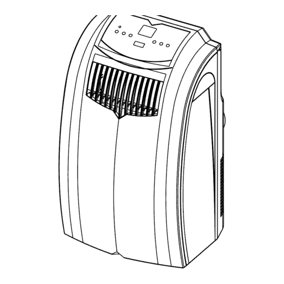
Page 3: Appearance
APPEARANCE Control panel Air outlet Handle hole Front panel APPEARANCE Rear panel outlet (Heat exchange) Water outlet drain Power supply cord... -
Page 4: Troubleshooting
TROUBLESHOOTING Trouble Analysis -If the protector trip or fuse is blown. •Please wait for 3 minutes and start again, protector device may be preventing unit to work. Does •If batteries in the remote controller exhausted. •If the plug is not properly plugged•... -
Page 5: Warning Light
O P E RAT'| O N (Only HPR09XC7) Indication symbols on LCD >_r< Cooling mode _= Highfanspeed Dehumidifymode Medfanspeed &_ Fan only mode Low fan speed Display set temperature Warning light the machine will stop running _._ 88h¢ Display timer setting of auto switch on/off Power Control •... -
Page 6: Operation
O P E RATION (Only HPR09XH7) Indication symbols on LCD >_r< Cooling mode _= Highfanspeed Dehumidifymode Medfanspeed Fan only mode Low fan speed Heating mode Display set temperature Warning light the machine will stop running _ 88hl- Display tirner setting of auto switch on/off Power Control •... -
Page 7: Remote Control
O P E RAT | O N (Only HPR09XC7) Conditioner Remote Control The functions work the same as your air conditioner's touch controls. All key function can be accessed from the remote control. CONTROL PANEL On/Off ® Used for adjusting the timer temperature. -
Page 8: Remote Control
O P E RAT|ON (Only HPR09XH7) Conditioner Remote Control The functions work the same as your air conditioner's touch controls. All key function can be accessed from the remote control. CONTROL PANEL On/Off ® Used for adjusting the timer temperature. •... -
Page 9: Technical Specifications
TECHNICAL SPECIFiCATiONS ITEM UNIT WAP-267DA OUTER DIMENSION 435W*770H*430D REFERENTIAL USING 13-_19 AREA RATED VOLTAGE V/Hz 115 / 60 COOLING CAPACITY B,T,U. 9000 DEHUMIDIFYING CAPACITY RUNNING CURRENT POWER CONSUMPTION INDOOR AIR VOLUME M_/hr 2R12S3R126A MODEL INPUT POWER OPERATING uF/V 35/250 COMPRESSOR CYCLE PROTECTOR MRA98503 or MRA98706... - Page 10 TECHNICAL SPECIFiCATiONS ITEM UNIT WAP-267DAH OUTER DIMENSION 435W*770H*430D REFERENTIAL USING 13-_19 AREA RATED VOLTAGE V/Hz 115/60 CAPACITY(Cooling/Heating) 2.6 / 2.6 DEHUMIDIFYING CAPACITY CURRENT(Cooling/Heating) 8.0 ! 8.0 POWER CONSUMPTION (Cooling/Heating) 900 / 900 INDOOR AIR VOLUME M3/hr 2R12S3R126A MODEL INPUT POWER OPERATING COMPRESSORCYCLE uF/V...
-
Page 11: Refrigerator System Diagram
REFRIGERATOR SYSTEM DIAGRAM WAP-267DA CAPILLARY FILTER ¢0 <:: COMPRESSOR REFRIGERATOR SYSTEM DIAGRAM WAP-267DAH CAPILLARY FILTER COMPRESSOR =t0=... -
Page 12: Schematic Wiring Diagram
SCHEMATIC WIRING DIAGRAM WAP-267DA T_0_L-_ L AC CORD MICROB.W. SENSOR WATER MOTOR BLUE A6950-240 SCHEMATICWIRING DIAGRAM WAP=267DAH MICROS.W. CONNECTOR CN _ C_4 C_ 2 BLACK WHITE AC CORD YELLOW _/GREEN REDRE OUTDOOR O_NGE COMPRESSOR MOTOR WATER )MOTOR CAPACITOR = BLUE BLUE CAPACIT BLUE...