D-Link DGS-1216T Manual
16-port 10/100/1000mbps gigabit ethernet switch + 2-port mini gbic web-smart switch
Hide thumbs
Also See for DGS-1216T:
- Product manual (52 pages) ,
- Getting started manual (43 pages) ,
- User manual (39 pages)

Related Manuals for D-Link DGS-1216T


Summary of Contents for D-Link DGS-1216T
- Page 1 D-Link DGS-1216T 16-Port 10/100/1000Mbps Gigabit Ethernet Switch + 2-Port mini GBIC Web-Smart Switch Manual Second Edition Building Networks for People...
-
Page 3: Table Of Contents
TABLE OF CONTENT About This Guide................. 1 Purpose .................... 1 Terms/Usage ..................1 Introduction..................3 Gigabit Ethernet Technology ............3 Fast Ethernet Technology ..............4 Switching Technology ..............5 VLAN (Virtual Local Area Network)..........6 Features.................... 6 Unpacking and Installation ..............9 Unpacking.................. - Page 4 Installing the Web Management Utility......... 18 Discovery List................19 Monitor List ................... 20 Device Setting................22 Toolbar................... 23 Configuring the Switch ..............24 Login....................25 Setup Menu ..................26 Configuring Setup Setting.............. 28 Port Settings................28 VLAN Settings (Virtual Local Area Network) ......31 Trunk Setting ................
- Page 5 Technical Specifications ..............48...
-
Page 7: About This Guide
ABOUT THIS GUIDE Congratulations on your purchase of the DGS-1216T 16-Port 10/100/1000Mbps Gigabit Ethernet+2-Port Mini GBIC Web Smart Switch. This device integrates 1000Mbps Gigabit Ethernet, 100Mbps Fast Ethernet and 10Mbps Ethernet network capabilities in a highly flexible package. Purpose This guide discusses how to install and configure the DGS-1216T Web Smart Switch. -
Page 9: Introduction
INTRODUCTION This chapter describes the features of the DGS-1216T and some background information about Ethernet/Fast Ethernet/Gigabit Ethernet switching technology. Gigabit Ethernet Technology Gigabit Ethernet is an extension of IEEE 802.3 Ethernet utilizing the same packet structure, format, and support for CSMA/CD protocol, full duplex, flow control, and management objects, but with a tenfold increase in theoretical throughput over 100-Mbps Fast Ethernet and a hundredfold increase over 10-Mbps Ethernet. -
Page 10: Fast Ethernet Technology
tomorrow’s rapidly improving switching and routing internetworking technologies. And with expected advances in the coming years in silicon technology and digital signal processing that will enable Gigabit Ethernet to eventually operate over unshielded twisted-pair (UTP) cabling, outfitting your network with a powerful 1000-Mbps- capable backbone/server connection creates a flexible foundation for the next generation of network technology products. -
Page 11: Switching Technology
Switching Technology Another approach to pushing beyond the limits of Ethernet technology is the development of switching technology. A switch bridges Ethernet packets at the MAC address level of the Ethernet protocol transmitting among connected Ethernet or Fast Ethernet LAN segments. -
Page 12: Vlan (Virtual Local Area Network)
VLAN (Virtual Local Area Network) A VLAN is a group of end-stations that are not constrained by their physical location and can communicate as if a common broadcast domain, a LAN. The primary utility of using VLAN is to reduce latency and need for routers, using faster switching instead. - Page 13 Up to 8K unicast addresses entities per device, self-learning, and table aging 512KBytes packet buffer Supports IEEE 802.3x flow control for full-duplex mode ports Supports IEEE 802.1Q-based VLAN Supports IEEE 802.1P-based QoS Supports Port-trunking Supports Port-mirroring Supports Port-setting for Speed/Disable, Flow control and Port Priority Support Jumbo-frame setting Supports IEEE 802.1D Spanning Tree protocol...
-
Page 15: Unpacking And Installation
UNPACKING AND INSTALLATION This chapter provides unpacking and installation information for the Switch. Unpacking Open the shipping cartons of the Switch and carefully unpacks its contents. The carton should contain the following items: One DGS-1216T Web Smart Switch One AC power cord, suitable for your area’s electrical power connections Four rubber feet to be used for shock cushioning Screws and two mounting brackets... -
Page 16: Rack Mounting
Leave at least 10cm of space at the front and rear of the hub for ventilation. Install the Switch on a sturdy, level surface that can support its weight, or in an EIA standard-size equipment rack. For information on rack installation, see the next section, Rack Mounting. -
Page 17: Connecting Network Cable
Then, use screws provided with the equipment rack to mount each switch in the rack. Figure 3. Mount the Switch in the rack Connecting Network Cable The Switch supports 1000Mbps Gigabit Ethernet that runs in Auto- negotiation mode and 10Mbps Ethernet or 100Mbps Fast Ethernet that runs both in half and full duplex mode and 1000Mbps Gigabit Ethernet runs in full duplex mode using four pair of Category 5 Cable. -
Page 19: Identifying External Components
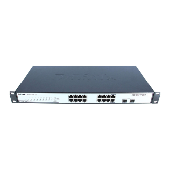
IDENTIFYING EXTERNAL COMPONENTS This chapter describes the front panel, rear panel, and LED indicators of the Switch. Front Panel The figure below shows the front panels of the Switch. Figure 4. Front panel of 16-port Gigabit Ethernet Switch LED Indicator: Comprehensive LED indicators display the status of the switch and the network (see the LED Indicators chapter below). -
Page 20: Rear Panel
Rear Panel ● Reset button Figure 5. Rear panel of the Switch AC Power Connector: This is a three-pronged connector that supports the power cord. Plug in the female connector of the provided power cord into this connector, and the male into a power outlet. Supported input voltages range from 100-240V AC at 50-60Hz. -
Page 21: Understanding Led Indicators
UNDERSTANDING LED INDICATORS The front panel LEDs provides instant status feedback, and, helps monitor and troubleshoot when needed. Figure 6. LED indicators of the Switch Power and System LEDs POWER: Power Indicator : When the Power LED lights on, the Switch is receiving power. : When the Power turns off or the power cord has improper connection. -
Page 22: Ports 1~16 Status Leds
Ports 1~16 Status LEDs Link/ACT: Link/Activity When the Link/ACT LED lights on, the respective port is successfully connected to an Ethernet network. Blinking When the Link/ACT LED is blinking, the port is transmitting or receiving data on the Ethernet network. No link. -
Page 23: Option Ports Mini-Gbic 15 & Mini-Gbic 16 Mini-Gbic Status Leds
Option Ports mini-GBIC 15 & mini-GBIC 16 mini-GBIC Status LEDs Link/ACT: Link/Activity When the mini-GBIC module is installed and connected to a network, the Link/ACT LED lights on. Blinking : When the LED is blinking, the mini-GBIC module is receiving data on a network. No link. -
Page 24: Configuration
CONFIGURATION Through the Web Browser you can configure the Switch such as VLAN, Trunking, QoS… etc. With the attached Web Management Utility, you can easily discover all the Web Management Switch, assign the IP Address, changing the password and upgrading the new firmware. Installing the Web Management Utility The following gives instructions guiding you through the installations of the Web Management utility. -
Page 25: Discovery List
Figure 7. Web Management Utility The Web Management Utility was divided into four parts, Discovery List, Monitor List, Device Setting and Toolbar function, for details instruction, follow the below section. Discovery List This is the list where you can discover all the Web management devices in the entire network. -
Page 26: Monitor List
System word definitions in the Discovery List: MAC Address: Shows the device MAC Address. IP Address: Shows the current IP address of the device. Protocol version: Shows the version of the Utility protocol. Product Name: Shows the device product name. System Name: Shows the appointed device system name. - Page 27 View Trap: The Trap function can receive the events that happen from the Web Management Switch in the Monitor List. There is a light indicator behind the “View Trap” button, when the light indicates in green, it means that there is no trap transmitted, and else when it indicates in red, it means that there is new trap transmitted, this is to remind us to view the trap.
-
Page 28: Device Setting
Device Setting You can set the device by using the function key in the Device Setting Dialog box. Configuration Setting: In this Configuration Setting, you can set the IP Address, Subnet Mask, Gateway, Set Trap to (Trap IP Address), System name and Location. Select the device in the Discovery list or Monitor List and press this button, then the Configuration Setting window will pop out as Figure 10, after filling up the data that you want to change, you must fill up... -
Page 29: Toolbar
Firmware Upgrade: When the device has a new function, there will be a new firmware to update the device, use this function to update. Figure 12. Firmware upgrade Web Access: Double click the device in the Monitor List or select a device in the Monitor List and press this “Web Access”... -
Page 30: Configuring The Switch
Exit: To exit the Web Management Utility. In the “View TAB”, there are view log and clear log function, this function will help you to show trap setting. View Log: To show the event of the Web Management Utility and the device. -
Page 31: Login
Login Before you configure this device, note that when the Web Smart Switch is configured through an Ethernet connection, make sure the manager PC must be set on same the IP network. For example, when the default network address of the default IP address of the Web Smart Switch is 192.168.0.1, then the manager PC should be set at 192.168.0.x (where x is a number between 2 and 254), and the default subnet mask is 255.255.255.0. -
Page 32: Setup Menu
After entering the password, the main page comes up, the screen will display the device status. Figure 15. Device Status Setup Menu When the main page appears, find the Setup menu in the left side of the screen (Figure 16). Click on the setup item that you want to configure. - Page 33 Figure 16. Setup menu...
-
Page 34: Configuring Setup Setting
Configuring Setup Setting Find that there are eight items, including Port Settings, VLAN Settings, Trunk Settings, Mirror Settings, QoS Setting, Spanning Tree Setting, SNMP Setting and Jumbo Frame Setting in Setup menu. Port Settings In Port Settings menu (Figure 17), this page will show each port’s status, press the ID parameter to set each port’s Speed, Flow Control. - Page 35 The priority of Gigabit Fiber port is higher than Copper. To change the port setting, click on the ID parameter to enter to the selected port to configure its Speed/Disable and Flow control setting. Figure 18. Speed/Disable: This setting has six modes—100M Full, 100M Half, 10M Full, 10M Half, Auto and Disable—for speed or port disable selections.
- Page 36 The Default Priority is specific the 802.1P QoS priority level to related port, all of the received data packet will follow the Default Priority level forwarding data packet to other port.
-
Page 37: Vlan Settings (Virtual Local Area Network)
VLAN Settings (Virtual Local Area Network) VID Table Setting: select the VID group that you set. When you select VID Table Setting, press “Add new VID” to create new VID group, from port 01 ~ port 16, select Untag Port, Tag Port or Not Member for each port. -
Page 38: Trunk Setting
Trunk Setting The Trunk function enables to cascade two or more devices with a larger bandwidths. There are two Trunk groups to be set; and there are default ports in each member. Checked “Enable” to use the trunk function, select the ports in each member to be trunk, and click “Apply”... -
Page 39: Ieee 802.1P Qos Setting
The selection of the sniffer mode is as follow: TX (transmit) mode: this mode will duplicate the data transmit from the source port and forward to the sniffer port. RX (receive) mode: this mode will duplicate the data that send to the source and forward to the sniffer port. - Page 40 more frequently - with every Hello packet. BPDU packets are sent even if a BPDU packet was not received. Therefore, each link between bridges is sensitive to the status of the link. Ultimately this difference results in faster detection of failed links, and thus faster topology adjustment.
-
Page 41: Snmp Setting
switch has the lowest Bridge Identifier, it will become the Root Bridge. The user may choose a time between 6 and 40 seconds. The default value is 20. Bridge Hello Time: The user may set the time interval between transmission of configuration messages by the root device, thus stating that the Switch is still functioning. - Page 42 manage the device. These objects are defined in a Management Information Base (MIB), which provides a standard presentation of the information controlled by the on-board SNMP agent. SNMP defines both the format of the MIB specifications and the protocol used to access this information over the network. The Switch supports the SNMP versions 1.
- Page 43 management software. In addition to the standard MIB-II, the Switch also supports its own proprietary enterprise MIB as an extended Management Information Base. The proprietary MIB may also be retrieved by specifying the MIB Object Identifier. MIB values can be either read-only or read-write.
- Page 44 Delete Group: To delete previously defined SNMP Community group, press “Delete Group” button, the Delete SNMP Community configuration window will pop out; checked the delete dialog box. Press “Apply” to delete the selected SNMP Community Group. Figure 27. Delete SNMP Community group Modify Group: To modify previously defined SNMP Community group, click on the ID parameter to enter to the selected SNMP Community Group to configure its community name and...
- Page 45 Configure SNMP Trap: Figure 29. Configure SNMP Trap Setting Trap authentication fail: When checked the dialog box of the Trap authentication fail, when fail to authentication, the Switch will trap the authentication fail even to the SNMP host. Add Trap: To create a recipient of SNMP traps generated by the Switch’s SNMP agent, press “Add Trap”...
- Page 46 Delete Trap: To delete previously defined SNMP Trap, press “Delete Trap” button, the Delete SNMP Trap Delete configuration window will pop out; checked the delete dialog box. Press “Apply” to delete the selected SNMP Trap setting. Figure 31. Delete SNMP Trap Modify Trap: To modify previously defined SNMP Trap, click on the ID parameter to enter to the selected SNMP Trap to configure its community name, IP address and events.
-
Page 47: Jumbo Frame Setting
Jumbo Frame Setting To enable or disable the Jumbo Frame function on the Switch. Figure 33. Jumbo frame setting Device Status Click on the “Status” to present the device status on this screen, it will show the System Status, Port Status, VLAN Status, Trunk Status and Mirror Status. -
Page 48: Statistic
Statistic The Statistic Menu screen will show the status of each port packet count. Figure 35. Device statistic For Detail packet information, click on the ID parameter as Figure 36. Figure 36. Port statistic... -
Page 49: System Setting
System Setting The System Setting includes the System name, Location name, Login Timeout, IP Address, Subnet Mask and Gateway. Through the Web Management Utility, you can easily recognize the device by using the System Name and the Location Name. The Login Timeout is to set the idle time-out for security issue, when there is no action in running the Web Smart Utility and the time is up, you must re-login to Web Smart Utility before you set the Utility. -
Page 50: Trap Setting
Trap Setting The Trap Setting enables the device to monitor the Trap through the Web Management Utility, set the Trap IP Address of the manager where the trap to be sent. Figure 38. Trap Setting System Events: Monitoring the system’s trap. Device Bootup: a trap when booting up the system. -
Page 51: Set Password
Abnormal* Receive Error: a trap when there are receive data error in copper port. Abnormal* Transmit Error: a trap when there are transmit data error in copprt port. Abnormal*: 50 error packet count within 10 seconds. Set Password Password is the invaluable tool for the manager to secure Web Management Switch, use this function to change the password. -
Page 52: Backup Setting
Backup Setting The backup tools help you to backup the current setting of the Switch. Once you need to backup the setting, press the “Backup” button to save the setting. To restore a current setting file to the device, you must specify the backup file and press “Restore”... -
Page 53: Logout
Logout When press this function, the web configuration will go back to first Login page. Figure 42. Logout... -
Page 54: Technical Specifications
TECHNICAL SPECIFICATIONS General Standards IEEE 802.3 10BASE-T Ethernet IEEE 802.3u 100BASE-TX Fast Ethernet IEEE 802.3ab 1000BASE-T Gigabit Ethernet IEEE 802.3x Full Duplex Flow Control IEEE 802.3z 1000BASE-SX/LX Gigabit Ethernet Protocol CSMA/CD Data Transfer Rate Ethernet: 10Mbps (half duplex), 20Mbps (full-duplex) Fast Ethernet: 100Mbps (half duplex), 200Mbps (full-duplex) Gigabit Ethernet: 2000Mbps (full-duplex) Topology... - Page 55 Performance Transmits Method: Store-and-forward Filtering Address 8K entries per device Table: Packet 10Mbps Ethernet: 14,880/pps Filtering/Forwarding 100Mbps Fast Ethernet: 148,800/pps Rate: 1000Mbps Gigabit Ethernet: 1,488,000/pps Address Automatic update Learning: Transmits Method: Store-and-forward RAM Buffer: 512K bytes per device...
- Page 56 The customer must submit with the product as part of the claim a written description of the Hardware defect or Software nonconformance in sufficient detail to allow D-Link to confirm the same, along with proof of purchase of the product (such as a copy of the dated purchase invoice for the product) if the product is not registered.
- Page 57 Warranty provides specific legal rights and you may also have other rights which vary from state to state. Trademarks: D-Link is a registered trademark of D-Link Systems, Inc. Other trademarks or registered trademarks are the property of their respective owners.
- Page 58 Product Registration Register online your D-Link product at http://support.dlink.com/register/ Product registration is entirely voluntary and failure to complete or return this form will not diminish your warranty rights.
-
Page 59: International Offices
Hsin-Tien, Taipei URL: www.dlink.dk URL: www.dlink.com.au Taiwan TEL: 886-2-2910-2626 Norway India FAX: 886-2-2910-1515 Karihaugveien 89 D-Link House, Kurla Bandra Complex Road URL: www.dlinktw.com.tw N-1086 Oslo Off CST Road, Santacruz (East) Norway Mumbai - 400098 Headquarters TEL: +47 99 300 100 India 2F, No. -
Page 60: Registration Card
8. What category best describes your company? Aerospace Engineering Education Finance Hospital Legal Insurance/Real Estate Manufacturing Retail/Chain store/Wholesale Government Transportation/Utilities/Communication System house/company Other________________________________ 9. Would you recommend your D-Link product to a friend? Don't know yet 10.Your comments on this product? __________________________________________________________________________________________ __________________________________________________________________________________________...