D-Link DGS-3420-28PC Hardware Installation Manual
Layer 2+ managed stackable gigabit switch
Hide thumbs
Also See for DGS-3420-28PC:
- Specifications (8 pages) ,
- Hardware installation manual (71 pages)
Table of Contents
Advertisement
Quick Links
Advertisement
Table of Contents

Related Manuals for D-Link DGS-3420-28PC


Summary of Contents for D-Link DGS-3420-28PC
- Page 2 © 2010 D-Link Corporation. All rights reserved. Reproduction in any manner whatsoever without the written permission of D-Link Corporation is strictly forbidden. Trademarks used in this text: D-Link and the D-LINK logo are trademarks of D-Link Corporation; Microsoft and Windows are registered trademarks of Microsoft Corporation.
-
Page 3: Table Of Contents
xStack® DGS-3420 Series Layer 2+ Managed Stackable Gigabit Switch Hardware Installation Reference Guide Table of Contents Intended Readers ................................v Typographical Conventions ............................v Notes, Notices, and Cautions ............................v Safety Instructions ................................. vi Safety Cautions ................................vi General Precautions for Rack-Mountable Products ....................vii Protecting Against Electrostatic Discharge ........................ - Page 4 xStack® DGS-3420 Series Layer 2+ Managed Stackable Gigabit Switch Hardware Installation Reference Guide Appendix Section ................................41 Appendix A – Technical Specifications ........................41 General ..................................41 Physical and Environmental............................41 Performance................................42 LED Indicators ................................43 Port Functions ................................44 Appendix B –...
-
Page 5: Intended Readers
DGS-3420-52P will be simply refered to as the Switch throughout this manual. All example screenshots are taken from the DGS-3420-28SC Switch. In some examples, where we refer to the Power over Ethernet examples, we’ll use the DGS-3420-28PC Switch. Typographical Conventions... -
Page 6: Safety Instructions
xStack® DGS-3420 Series Layer 2+ Managed Stackable Gigabit Switch Hardware Installation Reference Guide Safety Instructions Use the following safety guidelines to ensure your own personal safety and to help protect your system from potential damage. Throughout this safety section, the caution icon ( ) is used to indicate cautions and precautions that need to be reviewed and followed. -
Page 7: General Precautions For Rack-Mountable Products
xStack® DGS-3420 Series Layer 2+ Managed Stackable Gigabit Switch Hardware Installation Reference Guide • To help protect the system from sudden, transient increases and decreases in electrical power, use a surge suppressor, line conditioner, or uninterruptible power supply (UPS). • Position system cables and power cables carefully;... -
Page 8: Protecting Against Electrostatic Discharge
xStack® DGS-3420 Series Layer 2+ Managed Stackable Gigabit Switch Hardware Installation Reference Guide Protecting Against Electrostatic Discharge Static electricity can harm delicate components inside the system. To prevent static damage, discharge static electricity from your body before touching any of the electronic components, such as the microprocessor. This can be done by periodically touching an unpainted metal surface on the chassis. -
Page 9: Chapter 1 Introduction
DGS-3420 Series also suitable as a backbone solution for SMBs. The advanced ACL and user authentication functions on the Switch extend the network security coverage from core to the edge. A unique D-Link Safeguard Engine protects the DGS-3420 Series from the threat of worms and viruses, thereby increasing overall reliability,... -
Page 10: Features
Features The list of features below highlights the significant features of the Switch. • Supports Virtual Stacking. D-Link Single IP Management (SIM). • Supports Physical Stacking. Using the SFP+ ports with 40Gb (Full Duplex) in topologies Linear and Ring. •... -
Page 11: Ports
Supports Network Load Balancing (NLB) with both IPv4 and IPv6 support. • Supports Simple Mail Transfer Protocol (SMTP). • Support Ethernet Link Object Access Method (OAM) using 802.3ah D-Link Unidirectional Link Detection (DULD). • Supports Connectivity Fault Management (CFM) using 802.1ag. - Page 12 All the switches are equipt with one Redundant Power Supply (RPS) outlet for optional external RPS • All the switches are also equipt with one Alarm Port and SD Card Slot. NOTE: For customers interested in D-View, D-Link Corporation's proprietary SNMP management soft- ware, go to http://dview.dlink.com.tw/...
-
Page 13: Front-Panel Components
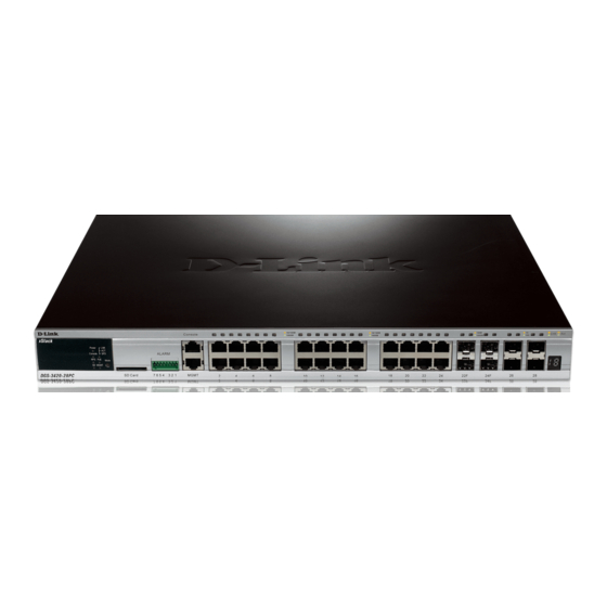
Figure 1–2 Front panel view of a DGS-3420-28TC Switch Figure 1–3 Front panel view of a DGS-3420-26SC Switch Figure 1–4 Front panel view of a DGS-3420-28PC Switch Figure 1–5 Front panel view of a DGS-3420-52T Switch Figure 1–6 Front panel view of a DGS-3420-52P Switch... -
Page 14: Led Indicators
The Switch front panel presents LED indicators for Power, Console, RPS, Master (stack control), SD, Stack ID and Link/Act indicators for all ports including the Gigabit Ethernet ports. The DGS-3420-28PC and DGS-3420-52P switches are equipt with an additional PoE light, to indication whether the ports are running in Power over Ethernet mode. - Page 15 10/100Mbps port is active. The LED remains dark when there is no link or activity. Only the DGS-3420-28PC and the DGS-3420-52P switches are equipt with a PoE LED. When this light is on with a solid green light, it means that the corresponding ports are feeding power to the PoE devices plugged in.
-
Page 16: Rear Panel Components
Figure 3-2 Rear panel view of a DGS-3420-28TC Switch Figure 3-3 Rear panel view of a DGS-3420-26SC Switch Figure 3-4 Rear panel view of a DGS-3420-28PC Switch Figure 3-5 Rear panel view of a DGS-3420-52T Switch Figure 3-6 Rear panel view of a DGS-3420-52P Switch The AC power connector is a standard three-pronged connector that supports the power cord. -
Page 17: Side Panel Components
Figure 4–1 Side panels of the DGS-3420-28SC Switch Figure 4–1 Side panels of the DGS-3420-28TC Switch Figure 4–1 Side panels of the DGS-3420-26SC Switch Figure 4–1 Side panels of the DGS-3420-28PC Switch... - Page 18 xStack® DGS-3420 Series Layer 2+ Managed Stackable Gigabit Switch Hardware Installation Reference Guide Figure 4–2 Side panels of the DGS-3420-52T Switch Figure 4–2 Side panels of the DGS-3420-52P Switch...
-
Page 19: Chapter 2 Installation
• One CD kit for CLI reference guide/Web UI reference guide/Hardware Installation Guide/D-View module If any item is missing or damaged, please contact your local D-Link Reseller for replacement. Installation Guidelines Please follow these guidelines for setting up the Switch: •... -
Page 20: Installing The Switch Without A Rack
xStack® DGS-3420 Series Layer 2+ Managed Stackable Gigabit Switch Hardware Installation Reference Guide Installing the Switch without a Rack First, attach the rubber feet included with the Switch if installing on a desktop or shelf. Attach these cushioning feet on the bottom at each corner of the device. -
Page 21: Mounting The Switch In A Standard 19" Rack
xStack® DGS-3420 Series Layer 2+ Managed Stackable Gigabit Switch Hardware Installation Reference Guide Mounting the Switch in a Standard 19" Rack Figure 2–3 Mount the switch in a rack Power On (AC Power) 1. Plug one end of the AC power cord into the power connector of the Switch and the other end into the local power source outlet. - Page 22 xStack® DGS-3420 Series Layer 2+ Managed Stackable Gigabit Switch Hardware Installation Reference Guide Figure 2-1. Alarm Connector Alarm Connector Port Contact Description Output. Normal Closed Pin. (42VAC or 60VDC) Output. Common Pin. (42VAC or 60VDC) Output. Normal Open Pin. (42VAC or 60VDC) Input 2 Input 2 Input 1...
-
Page 23: Installing Sfp And Sfp+ Ports
xStack® DGS-3420 Series Layer 2+ Managed Stackable Gigabit Switch Hardware Installation Reference Guide Installing SFP and SFP+ Ports The Switch is equipped with SFP (Small Form Factor Portable) and SFP+ ports, which are used with fiber-optical transceiver cabling.SFP ports support full-duplex transmissions, auto-negotiation, and can be uplinked with various other switches across a gigabit network. - Page 24 xStack® DGS-3420 Series Layer 2+ Managed Stackable Gigabit Switch Hardware Installation Reference Guide • DEM-330T/R (1000BASE-BX, WDM transceiver, Single-Mode 10km) • DEM-331T/R (1000BASE-BX, WDM transceiver, Single-Mode 40km) • DEM-CB100S-10-GbE SFP+1m Direct Attach Cable • DEM-CB300S-10-GbE SFP+3m Direct Attach Cable • DEM-CB700S-10-GbE SFP+7m Direct Attach Cable...
-
Page 25: Connecting To A Redundant Power Supply
4. Do not make any changes on the switch. NOTE: See the DPS-500 documentation for more information. CAUTION: Only the DGS-3420-28TC, DGS-3420-28SC, DGS-3420-26SC, and the DGS-3420- 52T uses DPS500. The DGS-3420-28PC and the DGS-3420-52P uses the DPS700. -
Page 26: External Redundant Power System
xStack® DGS-3420 Series Layer 2+ Managed Stackable Gigabit Switch Hardware Installation Reference Guide External Redundant Power System The DPS-500/700 is a redundant power-supply unit designed to conform to the voltage requirements of the switches being supported. The DPS-500/700 can be installed into a DPS-900, or DPS-800 rack mount unit. CAUTION: DO NOT connect the RPS to AC power before the DC power cable is connected. -
Page 27: Dps-800
xStack® DGS-3420 Series Layer 2+ Managed Stackable Gigabit Switch Hardware Installation Reference Guide Figure 2–7 Install the DPS-900 into the equipment rack CAUTION: Installing systems in a rack without the front and side stabilizers installed could cause the rack to tip over, potentially resulting in bodily injury under certain circumstances. Therefore, always install the stabilizers before installing components in the rack. - Page 28 xStack® DGS-3420 Series Layer 2+ Managed Stackable Gigabit Switch Hardware Installation Reference Guide The RPS can be mounted in a standard 19" rack. Use the following diagram to guide you. Figure 2–9 Install the DPS-800 in an Equipment Rack...
-
Page 29: Connecting The Switch
xStack® DGS-3420 Series Layer 2+ Managed Stackable Gigabit Switch Hardware Installation Reference Guide Chapter 3 Connecting the Switch Switch to End Node Switch to Switch Connecting To Network Backbone or Server Switch to End Node End nodes include PCs outfitted with a 10/100/1000 Mbps RJ-45 Ethernet Network Interface Card (NIC) and routers. An end node connects to the Switch via a twisted-pair UTP/STP cable. -
Page 30: Connect To A Network Backbone Or Server
xStack® DGS-3420 Series Layer 2+ Managed Stackable Gigabit Switch Hardware Installation Reference Guide Figure 3–2 Connect the Switch to a port on a switch with a straight or crossover cable Connect to a Network Backbone or Server The combo SFP ports and the 1000BASE-T ports are ideal for uplinking to a network backbone, server or server farm. The copper ports operate at a speed of 10/100/1000Mbps in half or full duplex mode. -
Page 31: Chapter 4 Introduction To Switch Management
xStack® DGS-3420 Series Layer 2+ Managed Stackable Gigabit Switch Hardware Installation Reference Guide Chapter 4 Introduction to Switch Management Management Options Connecting the Console Port Connecting to the Switch for the first time Connecting to the Management Port Password Protection Assigning IP Addresses SNMP Settings Management Options... - Page 32 xStack® DGS-3420 Series Layer 2+ Managed Stackable Gigabit Switch Hardware Installation Reference Guide • Under Properties, select VT100 for Emulation mode. • Select Terminal keys for Function, Arrow and Ctrl keys. Make sure to use Terminal keys (not Windows keys) are selected.
-
Page 33: Connecting To The Switch For The First Time
DGS-3420-28SC Gigabit Ethernet Switch Command Line Interface Firmware: Build 1.00.017 Copyright(C) 2011 D-Link Corporation. All rights reserved. UserName: Figure 4–2 Initial screen, first time connecting to the Switch Press Enter in both the Username and Password fields. Then access will be given to enter commands after the command prompt DGS-3420-28SC:admin# There is no initial username or password. -
Page 34: Password Protection
xStack® DGS-3420 Series Layer 2+ Managed Stackable Gigabit Switch Hardware Installation Reference Guide Password Protection The DGS-3420 Series Switches do not have a default user name and password. One of the first tasks when settings up the Switch is to create user accounts. Logging in using a predefined administrator-level user name will give the user privileged access to the Switch's management software. - Page 35 xStack® DGS-3420 Series Layer 2+ Managed Stackable Gigabit Switch Hardware Installation Reference Guide DGS-3420-28SC:admin# show switch Command: show switch Device Type : DGS-3420-28SC Gigabit Ethernet Switch Unit ID MAC Address : 00-01-02-03-04-00 IP Address : 192.168.69.123 (Manual) VLAN Name : default Subnet Mask : 255.255.255.0 Default Gateway...
-
Page 36: Snmp Settings
xStack® DGS-3420 Series Layer 2+ Managed Stackable Gigabit Switch Hardware Installation Reference Guide Figure 4–5 Assigning the Switch an IP Address In the above example, the Switch was assigned an IP address of 10.90.90.91 with a subnet mask of 255.0.0.0. (the CIDR form was used to set the address (10.90.90.91/8). -
Page 37: Management Information Base (Mib)
xStack® DGS-3420 Series Layer 2+ Managed Stackable Gigabit Switch Hardware Installation Reference Guide Management Information Base (MIB) The Switch in the Management Information Base (MIB) stores management and counter information. The Switch uses the standard MIB-II Management Information Base module. Consequently, values for MIB objects can be retrieved from any SNMP-based network management software. -
Page 38: Chapter 5 Web-Based Switch Configuration
xStack® DGS-3420 Series Layer 2+ Managed Stackable Gigabit Switch Hardware Installation Reference Guide Chapter 5 Web-based Switch Configuration Introduction Logging onto the Web Manager Web-based User Interface Web Pages Introduction All software functions of the Switch can be managed, configured, and monitored via the embedded Web-based (HTML) interface. -
Page 39: Web-Based User Interface
Switch's ports and expansion modules and shows port activity, depending on the specified mode. Some management functions, including port monitoring are accessible here. Click the D-Link logo to go to the D-Link Website. Area 3 Presents Switch status based on user selection and the entry of configuration data. In... -
Page 40: Web Pages
xStack® DGS-3420 Series Layer 2+ Managed Stackable Gigabit Switch Hardware Installation Reference Guide Web Pages When connecting to the management mode of the Switch with a Web browser, a login screen is displayed. Enter a user name and password to access the Switch's management mode. Below is a list of the main folders available in the Web interface: System Configuration - In this section the user will be able to configure features regarding the Switch’s configuration. -
Page 41: Appendix Section
IEEE 802.3u compliance Support Full-Duplex operations IEEE 802.3x Flow Control support for Full-Duplex mode IEEE 802.3ab compliance IEEE 802.3af compliance (DGS-3420-28PC & DGS-3420-52P only) IEEE 802.3at compliance (DGS-3420-28PC & DGS-3420-52P only) IEEE 802.3z compliance IEEE 802.3ae compliance IEEE 802.3aq compliance... -
Page 42: Performance
DGS-3420-28TC: 441mm (W) x 310mm (D) x 44mm (H) DGS-3420-26SC: 441mm (W) x 310mm (D) x 44mm (H) DGS-3420-28PC: 441mm (W) x 380mm (D) x 44mm (H) DGS-3420-52T: 441mm (W) x 380mm (D) x 44mm (H) DGS-3420-52P: 441mm (W) x 380mm (D) x 44mm (H) Weight DGS-3420-28SC: 4.15kg... -
Page 43: Led Indicators
G: When Safeguard Engine entering the exhausted mode. Port LED Mode A LED Mode Select Button to switch two modes in turn for all Indicator 10/100/1000Mbps ports on DGS-3420-28PC/52P: - Link/Act/Speed Mode - PoE Mode Green Solid Light A LED Mode Select Button to switch... -
Page 44: Port Functions
• IEEE 802.3 compliance • IEEE 802.3u compliance Support Full-Duplex operations • IEEE 802.3x Flow Control support for Full-Duplex mode • IEEE 802.3ab compliance • IEEE 802.3af compliance (DGS-3420-28PC & DGS-3420-52P only) • IEEE 802.3at compliance (DGS-3420-28PC & DGS-3420-52P only) - Page 45 xStack® DGS-3420 Series Layer 2+ Managed Stackable Gigabit Switch Hardware Installation Reference Guide SFP ports compliant to following standards: • IEEE 802.3z compliance SFP Transceivers Supported: • DEM-310GT (1000BASE-LX, Single-mode, 10km) • DEM-311GT (1000BASE-SX, Mutli-mode, 500m) • DEM-312GT2 (1000BASE-SX, Multi-mode, 2km) •...
- Page 46 2, 3, 6 and 8 of CAT3~6A UTP cables for 802.3af devices; or CAT5e~6A UTP cables for 802.3at devices. • DGS-3420-28PC, DGS-3420-52P works with all D-Link 802.3af and 802.3at capable devices It also works with all non-802.3af and non-802.3at capable D- Link Access Points, IP Cameras and IP phones using the DWL-P50 PoE adapter.
-
Page 47: Appendix B - Cables And Connectors
xStack® DGS-3420 Series Layer 2+ Managed Stackable Gigabit Switch Hardware Installation Reference Guide Appendix B – Cables and Connectors Ethernet Cable When connecting the Switch to another switch, a bridge or hub, a normal cable is necessary. Please review these products for matching cable pin assignment. -
Page 48: Console Cable
xStack® DGS-3420 Series Layer 2+ Managed Stackable Gigabit Switch Hardware Installation Reference Guide Console Cable When connecting the Switch to a PC, a Console cable is necessary. The following diagrams and tables show the standard Console-to-DJ-45 receptacle/connector and their pin assignments. Figure 5–4 Console-to-RJ-45 Cable Console-RJ-45 Pin Assignments Console (DB9/RS232) -
Page 49: Redundant Power Supply (Rps) Cable
RPS connector and their pin assignments. NOTE: The DGS-3420-28PC and the DGS-3420-52P use the RPS-700 and not the RPS-500. Both devices have their own cables included in the package. - Page 50 xStack® DGS-3420 Series Layer 2+ Managed Stackable Gigabit Switch Hardware Installation Reference Guide NC/GND NC/GND +12vsen +12Ven LS-54v LS-54V -54V -54V -54Vrtn -54Vrtn GND/NC GND/NC RPS Present RPS Present Status_1 RPS PG Status_2 RPS PG Status_1 Status_2 +12VRTNsen +12VRTNsen LS+12V LS+12V -54Vsen -54Vsen...
-
Page 51: Appendix C - Module Specs And Cable Lengths
xStack® DGS-3420 Series Layer 2+ Managed Stackable Gigabit Switch Hardware Installation Reference Guide Appendix C – Module Specs and Cable Lengths Use the following table to as a guide for the module specs and maximum cable lengths. Standard Media Type Maximum Distance Mini-GBIC 1000BASE-LX, Single-mode fiber module... -
Page 52: Warranties
xStack® DGS-3420 Series Layer 2+ Managed Stackable Gigabit Switch Hardware Installation Reference Guide Warranties... -
Page 53: Technical Support
xStack® DGS-3420 Series Layer 2+ Managed Stackable Gigabit Switch Hardware Installation Reference Guide Technical Support...