Asus M4A89TD PRO/USB3 User Manual
M4a89td pro series
Hide thumbs
Also See for M4A89TD PRO/USB3:
- User manual (2 pages) ,
- Supplementary manual (27 pages) ,
- User manual (132 pages)
Table of Contents
Advertisement
Advertisement
Table of Contents

Related Manuals for Asus M4A89TD PRO/USB3


Summary of Contents for Asus M4A89TD PRO/USB3
- Page 1 M4A89TD PRO Series M4A89TD PRO/USB3 M4A89TD PRO...
- Page 2 Product warranty or service will not be extended if: (1) the product is repaired, modified or altered, unless such repair, modification of alteration is authorized in writing by ASUS; or (2) the serial number of the product is defaced or missing.
-
Page 3: Table Of Contents
Product introduction Welcome! ....................1-1 Package contents..................1-1 Special features..................1-2 1.3.1 Product highlights................ 1-2 1.3.2 ASUS Xtreme Design—Hybrid Processor* ......... 1-2 1.3.3 ASUS Xtreme Design—Hybrid Switches* ........1-3 1.3.4 ASUS Xtreme Design—Hybrid OS ..........1-3 1.3.5 ASUS unique features..............1-3... - Page 4 BIOS setup Knowing BIOS .................... 3-1 Updating BIOS .................... 3-1 3.2.1 ASUS Update utility..............3-2 3.2.2 ASUS EZ Flash 2 utility ............... 3-4 3.2.3 ASUS CrashFree BIOS 3 utility........... 3-5 3.2.4 ASUS BIOS Updater ..............3-6 BIOS setup program .................. 3-9 3.3.1...
- Page 5 Boot Device Priority..............3-31 3.8.2 Boot Settings Configuration ............3-32 3.8.3 Security ..................3-33 Tools menu ....................3-35 3.9.1 ASUS EZ Flash 2 ..............3-35 3.9.2 Express Gate ................3-35 3.9.3 ASUS O.C. Profile ..............3-36 3.9.4 AI NET 2 ..................3-37 3.10...
- Page 6 Audio configurations..............4-8 ASUS Unique Overclocking Utility—TurboV EVO ........4-9 4.4.1 Using ASUS TurboV ..............4-9 4.4.2 Using ASUS TurboV Auto Tuning Mode ........4-10 4.4.3 Using CPU Level UP ..............4-11 4.4.4 Using ASUS Turbo Key ............. 4-11 RAID configurations ................4-12 4.5.1...
-
Page 7: Notices
Complying with the REACH (Registration, Evaluation, Authorisation, and Restriction of Chemicals) regulatory framework, we published the chemical substances in our products at ASUS REACH website at http://green.asus.com/english/REACH.htm. DO NOT throw the motherboard in municipal waste. This product has been designed to enable proper reuse of parts and recycling. -
Page 8: Safety Information
Safety information Electrical safety • To prevent electrical shock hazard, disconnect the power cable from the electrical outlet before relocating the system. • When adding or removing devices to or from the system, ensure that the power cables for the devices are unplugged before the signal cables are connected. If possible, disconnect all power cables from the existing system before you add a device. -
Page 9: About This Guide
Where to find more information Refer to the following sources for additional information and for product and software updates. ASUS websites The ASUS website provides updated information on ASUS hardware and software products. Refer to the ASUS contact information. Optional documentation Your product package may include optional documentation, such as warranty flyers, that may have been added by your dealer. -
Page 10: Conventions Used In This Guide
Conventions used in this guide To ensure that you perform certain tasks properly, take note of the following symbols used throughout this manual. DANGER/WARNING: Information to prevent injury to yourself when trying to complete a task. CAUTION: Information to prevent damage to the components when trying to complete a task. -
Page 11: M4A89Td Pro Series Specifications Summary
Windows 32-bit OS. ® *** Refer to www.asus.com or this user manual for the Memory QVL (Qualified Vendors Lists) Expansion slots 2 x PCI Express 2.0 x16 slots (@ dual x16 speed), support ATI CrossFireX™... - Page 12 - 6+2 Phase Power Design - ASUS EPU ASUS Exclusive Features - MemOK! ASUS Quiet Thermal Solutions - ASUS Fanless Design: Heat pipe solution - ASUS Fan Xpert ASUS EZ DIY - ASUS Q-DIMM - ASUS O.C. Profile - ASUS CrashFree BIOS 3 - ASUS EZ Flash 2 - ASUS MyLogo 2™...
- Page 13 System Panel BIOS features 16 Mb Flash ROM, SPI, AMI BIOS, PnP, DMI 2.0, WfM2.0, SM BIOS 2.5, ACPI 2.0a, Multi-language BIOS, ASUS EZ Flash 2, ASUS CrashFree BIOS 3 WfM 2.0, DMI 2.0, WOL by PME, WOR by PME, PXE...
-
Page 15: Chapter 1: Product Introduction
® The motherboard delivers a host of new features and latest technologies, making it another standout in the long line of ASUS quality motherboards! Before you start installing the motherboard, and hardware devices on it, check the items in your package with the list below. -
Page 16: Special Features
® transfer rate and PCI Express 2.0 interface. True USB 3.0 Support (M4A89TD PRO/USB3 model only) Experience ultra-fast data transfers at 4.8Gbps with USB 3.0—the latest connectivity standard. Built to connect easily with next generation components and peripherals, USB 3.0 transfers data 10X faster and is also backward compatible with USB 2.0 components. -
Page 17: Asus Xtreme Design-Hybrid Switches
1.3.4 ASUS Xtreme Design—Hybrid OS Express Gate Express Gate is an ASUS exclusive OS that provides you with quick access to the Internet and key applications before entering the Windows OS. Refer to pages 3-37 and 4-7 for details. ®... -
Page 18: Asus Quiet Thermal Solutions
BIOS file. This protection eliminates the need to buy a replacement ROM chip. ASUS EZ-Flash 2 ASUS EZ Flash 2 is a user-friendly utility that allows you to update the BIOS without using a bootable floppy disk or an OS-based utility. Refer to page 3-4 for details. Precision Tweaker 3 Allows you to adjust the CPU/NB voltage in 0.003125V steps and DRAM voltage in 0.00625V... -
Page 19: Chapter 2: Hardware Information
Before you install or remove any component, ensure that the ATX power supply is switched off or the power cord is detached from the power supply. Failure to do so may cause severe damage to the motherboard, peripherals, or components. ASUS M4A89TD PRO Series... -
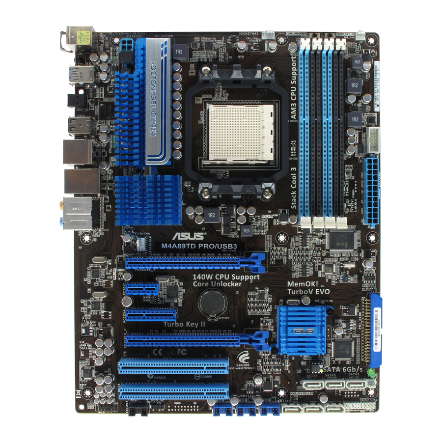
Page 20: Motherboard Overview
Motherboard overview 2.2.1 Motherboard layout Refer to 2.8 Connectors for more information about rear panel connectors and internal connectors. The NEC USB3.0 controller is for M4A89TD PRO/USB3 model only. Chapter 2: Hardware information... -
Page 21: Layout Contents
System panel connector (20-8 pin PANEL) 2-34 USB connectors (10-1 pin USB910, USB1112, USB1314) 2-30 Digital audio connector (4-1 pin SPDIF_OUT) 2-32 IEEE 1394a port connector (10-1 pin IE1394_2) 2-29 Front panel audio connector (10-1 pin AAFP) 2-32 ASUS M4A89TD PRO Series... -
Page 22: Placement Direction
2.2.3 Placement direction When installing the motherboard, ensure that you place it into the chassis in the correct orientation. The edge with external ports goes to the rear part of the chassis as indicated in the image below. 2.2.4 Screw holes Place nine screws into the holes indicated by circles to secure the motherboard to the chassis. -
Page 23: Central Processing Unit (Cpu)
Press the lever sideways to unlock the socket, then lift it up to a 90º angle. Socket lever Ensure that the socket lever is lifted up to a 90º angle. Otherwise, the CPU will not fit in completely. ASUS M4A89TD PRO Series... - Page 24 Position the CPU above the socket such that the CPU corner with the gold triangle matches the socket corner with a small triangle. Carefully insert the CPU into the socket until it fits in place. Gold triangle Small triangle When the CPU is in place, push down the socket lever to secure the CPU.
-
Page 25: Installing The Cpu Heatsink And Fan
Your boxed CPU heatsink and fan assembly should come with installation instructions for the CPU, heatsink, and the retention mechanism. If the instructions in this section do not match the CPU documentation, follow the latter. ASUS M4A89TD PRO Series... - Page 26 Attach one end of the retention bracket to the retention module base. Align the other end of the retention bracket to the retention module base. A clicking sound denotes that the retention bracket is in place. Ensure that the fan and heatsink assembly perfectly fits the retention mechanism module base, otherwise you cannot snap the retention bracket...
- Page 27 CPU_FAN. • Do not forget to connect the CPU fan connector! Hardware monitoring errors can occur if you fail to plug this connector. • This connector is backward compatible with old 3-pin CPU fan. ASUS M4A89TD PRO Series...
-
Page 28: System Memory
System memory 2.4.1 Overview The motherboard comes with four Double Data Rate 3 (DDR3) Dual Inline Memory Modules (DIMM) sockets. A DDR3 module has the same physical dimensions as a DDR2 DIMM but is notched differently to prevent installation on a DDR2 DIMM socket. DDR3 modules are developed for better performance with less power consumption. -
Page 29: Memory Configurations
• Due to the CPU spec., AMD AM3 100 and 200 series CPUs support up to DDR3 1066MHz. With ASUS design, this motherboard can support up to DDR3 1333MHz. • When overclocking, some AMD CPU models may not support DDR3 1600 or higher frequency DIMMs. - Page 30 M4A89TD PRO Series Motherboard Qualified Vendors Lists (QVL) DDR3-1066 MHz capability DIMM socket support (Optional) Vendor Part No. Size Chip Brand Chip NO. Timing Voltage 1 DIMM 2 DIMM 4 DIMM Crucial CT12864BA1067.8FF SS MICRON D9KPT • • • Crucial CT12864BA1067.8SFD SS MICRON D9JNL...
- Page 31 SS ELPIDA J1108BDSE-DJ-F • • • ELPIDA EBJ21UE8BAW0-DJ-E DS ELPIDA J1108BABG-DJ-E • ELPIDA EBJ21UE8BDF0-DJ-F DS ELPIDA J1108BDSE-DJ-F • • • ELPIDA EBJ21UE8EDF0-DJ-F DS ELPIDA J1108EDSE-DJ-F • • G.SKILL F3-10600CL7D-2GBPI 2GB(2 x SS - 1.65 • 1GB) ASUS M4A89TD PRO Series 2-13...
- Page 32 M4A89TD PRO Series Motherboard Qualified Vendors Lists (QVL) DDR3-1600 MHz capability DIMM socket support Chip Chip (Optional) Vendor Part No. Size SS/DS Timing Voltage Brand 1 DIMM 2 DIMM 4 DIMM A-DATA AD31600G001GMU 9-9-9-24 1.65~1.85 • • A-DATA AX3U1600GB1G9-AG 2GB(2 x 1GB) 9-9-9-24 1.65~1.85 •...
- Page 33 4 DIMMs: Supports four (4) modules inserted into both the blue and the black slots as two pairs of Dual-channel memory configuration. When using a DDR3 2000 memory module, ensure to install it on A1 slot for better overclocking capability. Visit the ASUS website for the latest QVL. ASUS M4A89TD PRO Series 2-15...
-
Page 34: Installing A Dimm
2.4.3 Installing a DIMM Ensure to unplug the power supply before adding or removing DIMMs or other system components. Failure to do so may cause severe damage to both the motherboard and the components. DIMM notch Unlock a DIMM socket by pressing the retaining clip outward. -
Page 35: Expansion Slots
When using PCI cards on shared slots, ensure that the drivers support “Share IRQ” or that the cards do not need IRQ assignments. Otherwise, conflicts will arise between the two PCI groups, making the system unstable and the card inoperable. Refer to the table on the next page for details. ASUS M4A89TD PRO Series 2-17... -
Page 36: Interrupt Assignments
2.5.3 Interrupt assignments Standard interrupt assignments Priority Standard function System Timer Keyboard Controller – Redirect to IRQ#9 Communications Port (COM1)* IRQ Holder for PCI Steering* Reserved Reserved System CMOS/Real Time Clock IRQ Holder for PCI Steering* IRQ Holder for PCI Steering* IRQ Holder for PCI Steering* Reserved Numeric Data Processor... -
Page 37: Pci Slots
We recommend that you provide sufficient power when running CrossFireX™ mode. See page 2-33 for details. • Connect a chassis fan to the motherboard connector labeled CHA_FAN1/2 when using multiple graphics cards for better thermal environment. See page 2-31 for details. ASUS M4A89TD PRO Series 2-19... -
Page 38: Onboard Switches
BIOS default settings. A messgae will appear during POST reminding you that the BIOS has been restored to its default settings. • We recommend that you download and update to the latest BIOS version from the ASUS website at www.asus.com after using the MemOK! function. 2-20 Chapter 2: Hardware information... - Page 39 You may use the TurboV Auto Tuning, overclock in the BIOS setup program, and enable the Turbo Key II function at the same time. However, the system will use the last setting you have made. ASUS M4A89TD PRO Series 2-21...
-
Page 40: Core Unlocker Switch
The system will use the last setting you have made. • If you clear the CMOS or load the BIOS setup defaults, the ASUS Core Unlocker item in the BIOS menu follows the current setting of the Core Unlocker switch. -
Page 41: Connectors
Connectors 2.7.1 Rear panel connectors Rear panel connectors USB 3.0 ports 7 and 8 (M4A89TD PRO/USB3) PS/2 mouse port (green) USB 2.0 ports 7 and 8 (M4A89TD PRO) Optical S/PDIF Out port USB 2.0 ports 5 and 6 USB 2.0 ports 3 and 4... -
Page 42: Audio I/O Connections
* LAN port LED indications ACT/LINK SPEED Activity Link LED Speed LED Status Description Status Description No link 10 Mbps connection ORANGE Linked ORANGE 100 Mbps connection BLINKING Data activity GREEN 1 Gbps connection LAN port ** Audio 2, 4, 6, or 8-channel configuration Headset Port 4-channel... - Page 43 Connect to Stereo / 2.1-channel Speakers Connect to 4.1 channel Speakers Connect to 5.1 channel Speakers ASUS M4A89TD PRO Series 2-25...
- Page 44 Connect to 7.1 channel Speakers 2-26 Chapter 2: Hardware information...
-
Page 45: Internal Connectors
This prevents incorrect insertion when you connect the IDE cable. • Use the 80-conductor IDE cable for Ultra DMA 133/100/66 IDE devices. If any device jumper is set as “Cable-Select”, ensure that all other device jumpers have the same setting. ASUS M4A89TD PRO Series 2-27... - Page 46 ® SB850 Serial ATA Serial ATA 6.0 Gb/s connectors (7-pin SATA 1-6) These connectors are for the Serial ATA 6.0 Gb/s signal cables for Serial ATA hard disk drives and optical disc drives. If you installed Serial ATA hard disk drives, you can create a RAID 0, RAID 1, RAID 5, ®...
- Page 47 Never connect a USB cable to the IEEE 1394a connector. Doing so will damage the motherboard! The IEEE 1394a module is purchased separately. ASUS M4A89TD PRO Series 2-29...
- Page 48 Never connect a 1394 cable to the USB connectors. Doing so will damage the motherboard! You can connect the front panel USB cable to the ASUS Q-Connector (USB, blue) first, and then install the Q-Connector (USB) to the USB connector onboard if your chassis supports front panel USB ports.
- Page 49 • The CPU_FAN connector supports the CPU fan of maximum 2A (24 W) fan power. • Only the CPU_FAN, CHA_FAN1 and CHA_FAN2 connectors support the ASUS Fan Xpert feature. • If you install two VGA cards, we recommend that you plug the rear chassis fan cable to the motherboard connector labeled CHA_FAN1 or CHA_FAN2 for better thermal environment.
- Page 50 Digital audio connector (4-1 pin SPDIF_OUT) This connector is for an additional Sony/Philips Digital Interface (S/PDIF) port. Connect the S/PDIF Out module cable to this connector, then install the module to a slot opening at the back of the system chassis. The S/PDIF module is purchased separately.
- Page 51 Recommended Power Supply Wattage Calculator at http://support. asus.com/PowerSupplyCalculator/PSCalculator.aspx?SLanguage=en-us for details. • If you want to use two high-end PCI Express x16 cards, use a PSU with 1000W power or above to ensure the system stability. ASUS M4A89TD PRO Series 2-33...
-
Page 52: System Panel Connector
System panel connector (20-8 pin PANEL) This connector supports several chassis-mounted functions. • System power LED (2-pin PLED) This 2-pin connector is for the system power LED. Connect the chassis power LED cable to this connector. The system power LED lights up when you turn on the system power, and blinks when the system is in sleep mode. -
Page 53: Asus Q-Connector (System Panel)
2.7.4. ASUS Q-Connector (system panel) Use the ASUS Q-Connector to connect/disconnect the chassis front panel cables. To install the ASUS Q-Connector: Connect the front panel cables to the ASUS Q-Connector. Refer to the labels on the Q-Connector to know the detailed pin definitions, and then match them to their respective front panel cable labels. -
Page 54: Onboard Leds
Onboard LEDs Standby Power LED The motherboard comes with a standby power LED. The green LED lights up to indicate that the system is ON, in sleep mode, or in soft-off mode. This is a reminder that you should shut down the system and unplug the power cable before removing or plugging in any motherboard component. - Page 55 Core Unlocker LED The Core Unlocker LED lights when the Core Unclocker switch is turned to Enable. The Core Unlocker LED keeps on lighting even though the ASUS Core Unlocker item in the BIOS menu is set to [Disabled]. ASUS M4A89TD PRO Series...
-
Page 56: Starting Up For The First Time
Starting up for the first time After making all the connections, replace the system case cover. Be sure that all switches are off. Connect the power cord to the power connector at the back of the system chassis. Connect the power cord to a power outlet that is equipped with a surge protector. Turn on the devices in the following order: Monitor External SCSI devices (starting with the last device on the chain) -
Page 57: Chapter 3: Bios Setup
Refer to the corresponding sections for details on these utilities. Save a copy of the original motherboard BIOS file to a USB flash disk in case you need to restore the BIOS in the future. Copy the original motherboard BIOS using the ASUS Update utility. -
Page 58: Asus Update Utility
3.2.1 ASUS Update utility The ASUS Update is a utility that allows you to manage, save, and update the motherboard BIOS in Windows environment. The ASUS Update utility allows you to: ® • Save the current BIOS file • Download the latest BIOS file from the Internet •... - Page 59 Auto Select. Click Next. Next. Follow the onscreen instructions to complete the update process. The ASUS Update utility is capable of updating itself through the Internet. Always update the utility to avail all its features. Updating the BIOS through a BIOS file...
-
Page 60: Asus Ez Flash 2 Utility
3.2.2 ASUS EZ Flash 2 utility The ASUS EZ Flash 2 feature allows you to update the BIOS without having to use a bootable floppy disk or an OS-based utility. Before you start using this utility, download the latest BIOS from the ASUS website at www.asus.com. -
Page 61: Asus Crashfree Bios 3 Utility
The BIOS file in the motherboard support DVD may be older than the BIOS file published on the ASUS official website. If you want to use the newer BIOS file, download the file at support.asus.com and save it to a USB flash drive. -
Page 62: Asus Bios Updater
3.2.4 ASUS BIOS Updater The ASUS BIOS Updater allows you to update BIOS in DOS environment. This utility also allows you to copy the current BIOS file that you can use as a backup when the BIOS fails or gets corrupted during the updating process. - Page 63 ASUSTek BIOS Updater for DOS V1.00b [09/06/22] FLASH TYPE: MXIC 25L1605A Current ROM Update ROM BOARD: M4A89TD PRO BOARD: Unknown Series VER: Unknown VER: 0206 DATE: Unknown PATH: BIOS backup is done! Press any key to continue. Note Saving BIOS: ASUS M4A89TD PRO Series...
- Page 64 Updating the BIOS file To update the BIOS file using BIOS Updater At the FreeDOS prompt, type bupdater /pc /g and press <Enter>. D:\>bupdater /pc /g The BIOS Updater screen appears as below. ASUSTek BIOS Updater for DOS V1.00b [09/06/22] FLASH TYPE: MXIC 25L1605A Current ROM...
-
Page 65: Bios Setup Program
For changing the advanced system settings Power For changing the advanced power management (APM) configuration Boot For changing the system boot configuration Tools For configuring options for special functions Exit For selecting the exit options and loading default settings ASUS M4A89TD PRO Series... -
Page 66: Navigation Keys
3.3.3 Navigation keys At the bottom right corner of a menu screen are the navigation keys for that particular menu. Use the navigation keys to select items in the menu and change the settings. The navigation keys may differ from one screen to another. 3.3.4 Menu items The highlighted item on the menu bar displays the specific items for that menu. -
Page 67: Main Menu
The BIOS automatically detects the values opposite the dimmed items (Device, Vendor, Size, LBA Mode, Block Mode, PIO Mode, Async DMA, Ultra DMA, and SMART Monitoring). These values are not user-configurable. These items show N/A if no SATA device is installed in the system. ASUS M4A89TD PRO Series 3-11... - Page 68 Type [Auto] Allows you to select the type of device installed. [Not Installed] Select this option if no device is installed. [Auto] Allows automatic selection of the appropriate device type. [CDROM] Select this option if you are specifically configuring a CD-ROM drive. [ARMD] Select [ARMD] (ATAPI Removable Media Device) if your device is either a ZIP, LS-120, or MO drive.
-
Page 69: Storage Configuration
SATA connectors 5/6 and set them to [IDE] mode. • The default setting and the configuration options of the SATA Port5-Port6 item vary with the selected setting of the SATA Port1-Port4 item. ASUS M4A89TD PRO Series 3-13... -
Page 70: System Information
3.4.3 System Information This menu gives you an overview of the general system specifications. The BIOS automatically detects the BIOS information, CPU specification, and system memory in this menu. BIOS SETUP UTILITY Main EC BIOS Version : MBEC-0007 BIOS Information Version : 0206 Build Date: 02/09/10... -
Page 71: Ai Tweaker Menu
Configuration options: [Auto] [Phenom II-955] [Phenom II-3.4G] [Phenom II-3.6G] • The configuration options vary depending on the CPU model you install on the motherboard. • The CPU Level UP function support depends on CPU types. ASUS M4A89TD PRO Series 3-15... -
Page 72: Oc Tuner Utility
3.5.2 OC Tuner Utility OC Tuner utility automatically overclocks the frequency and voltage of the CPU and DRAM. Press <Enter> to start auto tuning. It takes around five minutes, and the system will reboot for several times until auto tuning is completed. 3.5.3 Ai Overclock Tuner [Auto] Allows you to select the CPU overclocking options to achieve the desired CPU internal... -
Page 73: Cpu Ratio
Configuration options: [Auto] [15 CLK] – [30 CLK] DRAM READ to PRE Time [Auto] Configuration options: [Auto] [4 CLK] [5 CLK] [6 CLK] [7 CLK] DRAM Row Cycle Time [Auto] Configuration options: [Auto] [11 CLK] – [41 CLK] ASUS M4A89TD PRO Series 3-17... -
Page 74: Dram Driving Configuration
DRAM WRITE Recovery Time [Auto] Configuration options: [Auto] [5 CLK] [6 CLK] [7 CLK] [8 CLK] [10 CLK] [12 CLK] DRAM RAS# to RAS# Delay [Auto] Configuration options: [Auto] [4 CLK] [5 CLK] [6 CLK] [7 CLK] DRAM READ to WRITE Delay [Auto] Configuration options: [Auto] [3 CLK] –... -
Page 75: Cpu & Nb Voltage Mode
Allows you to set the CPU VDDA voltage. The values range from 2.20000V to 2.90000V with a 0.00625V interval. 3.5.12 DRAM Voltage [Auto] Allows you to set the DRAM voltage. The values range from 1.20000V to 2.50000V with a 0.00625V interval. ASUS M4A89TD PRO Series 3-19... -
Page 76: Cpu Load-Line Calibration
3.5.13 HT Voltage [Auto] Allows you to set the HyperTransport voltage. The values range from 0.80000V to 1.40000V with a 0.00625V interval. 3.5.14 NB Voltage [Auto] Allows you to set the Northbridge voltage. The values range from 0.80000V to 2.00000V with a 0.00625V interval. -
Page 77: Advanced Menu
Microcode Updation [Enabled] [Enabled] Allows the system to update the Microcode automatically, enhancing system performance. [Disabled] Disables this function. Secure Virtual Machine Mode [Enabled] [Enabled] Enables the AMD Secure Virtual Machine mode. [Disabled] Disables this function. ASUS M4A89TD PRO Series 3-21... -
Page 78: Chipset
[Enabled] Enables the AMD Cool’n’Quiet function. [Disabled] Disables this function. ASUS Core Unlocker [Disabled] [Enabled] Enables the ASUS Core Unlocker to get the full computing power of the processor. [Disabled] Disables this function. C1E Support [Enabled] [Enabled] Enables the C1E support function. This item should be enabled in order to enable the Enhanced Halt Sate. -
Page 79: Ecc Configuration
Set to [Max] to adjust ECC mode automatically. [User] Set to [User] to adjust all the subitems manually. Primary Display Adapter [PCI-E] Allows you to decide which graphics controller to use as the primary boot device. Configuration options: [PCI-E] [PCI] ASUS M4A89TD PRO Series 3-23... -
Page 80: Onboard Devices Configuration
3.6.3 Onboard Devices Configuration BIOS SETUP UTILITY Advanced Onboard Devices Configuration Allows BIOS to select Serial Port1 Base HD Audio Azalia Device [Enabled] Addresses. Front Panel Type [HD] SPDIF OUT Type [SPDIF] POST State LEDs [Enabled] Serial Port1 Address [3F8/IRQ4] Serial Port1 Mode [Normal] Onboard LAN... -
Page 81: Usb Configuration
This item appears only when you set the previous item to [Enabled]. [Enabled] Enables the onboard ATA controller ROM. [Disabled] Disables the onboard ATA controller ROM. Onboard USB 3.0 Controller [Enabled] (M4A89TD PRO/USB3 model only) [Enabled] Enables the USB 3.0 controller. [Disabled] Disables the controller. -
Page 82: Pcipnp
USB Support [Enabled] [Enabled] Enables the USB Host Controllers. [Disabled] Disables the controllers. The following items appear only when you set USB Support to [Enabled]. Legacy USB Support [Auto] [Auto] Allows the system to detect the presence of USB devices at startup. If detected, the USB controller legacy mode is enabled. -
Page 83: Power Menu
ACPI APIC Support [Enabled] [Disabled] The system disables the Advanced Configuration and Power Interface (ACPI) support in the Advanced Programmable Interrupt Controller (APIC). [Enabled] The ACPI APIC table pointer is included in the RSDT pointer list. ASUS M4A89TD PRO Series 3-27... -
Page 84: Apm Configuration
3.7.5 APM Configuration BIOS SETUP UTILITY Power APM Configuration EuP Ready [Disabled] Restore on AC Power Loss [Power Off] Power On By PCI/PCIE Device [Disabled] Power On By PS/2 Devices [Disabled] Power On By Ring [Disabled] Power On By RTC Alarm [Disabled] EuP Ready [Disabled] [Disabled]... -
Page 85: Hardware Monitor
Configuration options: [500RPM] [400RPM] [300RPM] [200RPM] [100RPM] [Ignored] Select Fan Type: [PWR Fan] [PWR Fan] Sets to [PWR Fan] when using a 4-pin CPU fan. [DC Fan] Sets to [DC Fan] when using a 3-pin CPU fan. ASUS M4A89TD PRO Series 3-29... - Page 86 CPU Q-Fan Mode [Optimal] [Turbo] Sets to [Turbo] to achieve maximum CPU fan speed. [Standard] Sets to [Standard] to make the CPU fan automatically adjust depending on the CPU temperature. [Silent] Sets to [Silent] to minimize the fan speed for quiet CPU fan operation.] [Manual] Sets to [Manual] to assign detailed fan speed control parameters.
-
Page 87: Boot Menu
Save and Exit Exit v02.61 (C)Copyright 1985-2010, American Megatrends, Inc. 3.8.1 Boot Device Priority BIOS SETUP UTILITY Boot Boot Device Priority 1st Boot Device [Removable Dev.] 2nd Boot Device [Hard Drive] 3rd Boot Device [ATAPI CD-ROM] ASUS M4A89TD PRO Series 3-31... -
Page 88: Boot Settings Configuration
Configuration options: [Removable Dev.] [Hard Drive] [ATAPI CD-ROM] [Disabled] • To select the boot device during system startup, press <F8> when ASUS Logo appears. • To access Windows OS in Safe Mode, do any of the following: - Press <F5>... -
Page 89: Security
Allows access but does not allow change to any field. [Limited] Allows changes only to selected fields, such as Date and Time. [Full Access] Allows viewing and changing all the fields in the Setup utility. ASUS M4A89TD PRO Series 3-33... - Page 90 Change User Password Select this item to set or change the user password. The User Password item on top of the screen shows the default Not Installed. After you set a password, this item shows Installed. To set a User Password: Select the Change User Password item and press <Enter>.
-
Page 91: Tools Menu
(C)Copyright 1985-2010, American Megatrends, Inc. 3.9.1 ASUS EZ Flash 2 Allows you to run ASUS EZ Flash 2. When you press <Enter>, a confirmation message appears. Use the left/right arrow key to select between [Yes] or [No], then press <Enter> to confirm your choice. -
Page 92: Asus O.c. Profile
Express Gate. The first time wizard will run again when you enter the Express Gate environment after clearing its settings. 3.9.3 ASUS O.C. Profile This item allows you to store or load multiple BIOS settings. BIOS SETUP UTILITY Tools O.C. PROFILE Configuration... -
Page 93: Ai Net 2
Check Realtek LAN cable [Disabled] Check Realtek LAN cable [Disabled] [Disabled] BIOS will not check the Realtek LAN cable during the Power-On Self-Test (POST). [Enabled] BIOS checks the Realtek LAN cable during the Power-On Self-Test (POST). ASUS M4A89TD PRO Series 3-37... -
Page 94: Exit Menu
3.10 Exit menu The Exit menu items allow you to load the optimal or failsafe default values for the BIOS items, and save or discard your changes to the BIOS items. BIOS SETUP UTILITY Main Ai Tweaker Advanced Power Boot Tools Exit Exit system setup... -
Page 95: Chapter 4: Software Support
The contents of the support DVD are subject to change at any time without notice. Visit the ASUS website at www.asus.com for updates. 4.2.1 Running the support DVD Place the support DVD into the optical drive. -
Page 96: Obtaining The Software Manuals
The software manual files are in Portable Document Format (PDF). Install the Adobe ® Acrobat Reader from the Utilities menu before opening the files. ® Click the Manual tab. Click ASUS Motherboard Utility Guide from the manual list on the left. The Manual folder of the support DVD appears. Double-click the folder of your selected software. -
Page 97: Software Information
Launching PC Probe II Install PC Probe II from the motherboard support DVD. Launch PC Probe II by clicking Start > All Programs > ASUS > PC Probe II > PC Probe II v1.xx.xx. The PC Probe II main window appears. -
Page 98: Asus Ai Suite
Launching AI Suite Install AI Suite from the motherboard support DVD. Launch AI Suite by clicking Start > All Programs > ASUS > AI Suite > AI Suite v1.xx. xx. The AI Suite main window appears. The AI Suite icon appears in the Windows notification area. -
Page 99: Asus Fan Xpert
4.3.3 ASUS Fan Xpert Asus Fan Xpert allows you to adjust both the CPU and chassis fan speeds according to different ambient temperatures and your PC’s system loading. The various fan profiles offer flexible controls of fan speeds to achieve a quiet and cool system environment. -
Page 100: Asus Epu
4.3.4 ASUS EPU ASUS EPU is an energy-efficient tool that provides you with a total system power-saving solution. It detects the current computer loading and intelligently adjusts the power in real- time. With auto phase switching for components, the EPU automatically provides the most... -
Page 101: Asus Express Gate
4.3.5 ASUS Express Gate ASUS Express Gate is an ASUS exclusive OS that provides you with quick access to the Internet and key applications before entering the Windows ® Notices about ASUS Express Gate • Install ASUS Express Gate from the motherboard support DVD before use. -
Page 102: Audio Configurations
4.3.6 Audio configurations The Realtek audio CODEC provides 8-channel audio capability to deliver the ultimate audio ® experience on your computer. The software provides Jack-Detection function, S/PDIF Out support, and interrupt capability. The CODEC also includes the Realtek proprietary UAJ ®... -
Page 103: Asus Unique Overclocking Utility-Turbov Evo
CPU permanently, and setting a low voltage may make the system unstable. For system stability, all changes made in ASUS TurboV (except for Auto Tuning) will not be saved to BIOS settings and will not be kept on the next system boot. Use the Save Profile function to save your customized overclocking settings and manually load the profile after Windows starts. -
Page 104: Using Asus Turbov Auto Tuning Mode
4.4.2 Using ASUS TurboV Auto Tuning Mode The Auto Tuning Mode allows smart auto-overclocking. Follow the instructions below to let TurboV EVO detect and overclock your system. Click the Auto Tuning tab and then click Start. You can also click More... -
Page 105: Using Cpu Level Up
4.4.4 Using ASUS Turbo Key ASUS Turbo Key allows the user to set a group of hotkeys into physical overclocking buttons. After the easy setup, Turbo Key can boost performances without interrupting ongoing work or games—with just one touch! Configuring ASUS Turbo Key Click the Turbo Key tab. -
Page 106: Raid Configurations
RAID configurations The motherboard comes with the AMD SB850 chipset that allows you to configure ® Serial ATA hard disk drives as RAID sets. The motherboard supports the following RAID configurations: RAID 0, RAID 1, RAID 5 and RAID 10. •... -
Page 107: Installing Serial Ata Hard Disks
When setting the SATA Port1-Port4 item to [RAID], all SATA ports run at RAID mode. However, you can set the SATA ports 5 and 6 to [IDE] or [AHCI] modes. See section 3.4.2 Storage Configuration for details. ASUS M4A89TD PRO Series 4-13... -
Page 108: Amd ® Option Rom Utility
4.5.4 Option ROM Utility ® To enter the AMD Option ROM utility: ® Boot up your computer. During POST, press <Ctrl> + <F> to display the utility main menu. Option ROM Utility (c) 2009 Advanced Micro Devices, Inc. [ Main Menu ] View Drive Assignments ..[ 1 ] LD View / LD Define Menu... -
Page 109: Creating A Raid Volume
<Press Ctrl-Y Key if you are sure to erase it> <Press any other key to ignore this option> Press <Ctrl> + <Y> to enter the screen to modify the array capacity, or press any key to use the maximum capacity. ASUS M4A89TD PRO Series 4-15... -
Page 110: Deleting A Raid Configuration
Deleting a RAID configuration Take caution when deleting a RAID volume. You will lose all data on the hard disk drives when you delete a RAID volume. To delete a RAID volume: In the Main Menu, press <3> to enter the Delete LD function. Select the RAID item you want to delete and press <Del>... -
Page 111: Creating A Raid Driver Disk
During the OS installation, the system prompts you to press the F6 key to install third-party SCSI or RAID driver. Press <F6>, and then insert the floppy disk with RAID driver into the USB floppy disk drive. ASUS M4A89TD PRO Series 4-17... -
Page 112: Using A Usb Floppy Disk Drive
When prompted to select the SCSI adapter to install, select the RAID driver for the corresponding OS version. Follow the succeeding screen instructions to complete the installation. To install the RAID driver for Windows Vista or later OS ® During the OS installation, click Load Driver to allow you to select the installation media containing the RAID driver. - Page 113 “PCI\VEN_1002&DEV_4393&CC_0104”,”ahcix86” id= “USB\VID_03EE&PID_6901”, “usbstor” [HardwareIds.SCSI.Napa_amd64_ahci] id= “PCI\VEN_1002&DEV_4392&CC_0104”,”ahcix64” id= “PCI\VEN_1002&DEV_4391&CC_0106”,”ahcix64” id= “PCI\VEN_1002&DEV_4393&CC_0104”,”ahcix64” id= “USB\VID_03EE&PID_6901”, “usbstor” Add the same line to both sections. The VID and PID vary with different vendors. Save and exit the file. ASUS M4A89TD PRO Series 4-19...
- Page 114 4-20 Chapter 4: Software support...
-
Page 115: Chapter 5: Ati ® Crossfirex™ Technology Support
For Windows XP, go to Control Panel > Add/Remove Programs. For Windows Vista, go to Control Panel > Programs and Features. Select your current graphics card drivers. For Windows XP, select Add/Remove. For Windows Vista, select Uninstall. Turn off your computer. ASUS M4A89TD PRO Series... -
Page 116: Installing Two Crossfirex™ Graphics Cards
5.1.3 Installing two CrossFireX™ graphics cards The following pictures are for reference only. The graphics cards and the motherboard layout may vary with models, but the installation steps remain the same. Prepare two CrossFireX-ready graphics cards. Insert the two graphics card into the PCIEX16 slots. -
Page 117: Installing The Device Drivers
In the Catalyst Control Center window, click Graphics Settings > CrossFireX > Configure. From the Graphics Adapter list, select the graphics card to act as the display GPU. Select Enable CrossFireX. Click Apply, and then click OK to exit the window. ASUS M4A89TD PRO Series... - Page 118 Chapter 5: ATI CrossFireX™ technology support ®...
-
Page 119: Asus Contact Information
+1-812-282-3777 +1-510-608-4555 Web site usa.asus.com Technical Support Telephone +1-812-282-2787 Support fax +1-812-284-0883 Online support support.asus.com ASUS COMPUTER GmbH (Germany and Austria) Address Harkort Str. 21-23, D-40880 Ratingen, Germany +49-2102-959911 Web site www.asus.de Online contact www.asus.de/sales Technical Support Telephone +49-1805-010923* Support Fax...