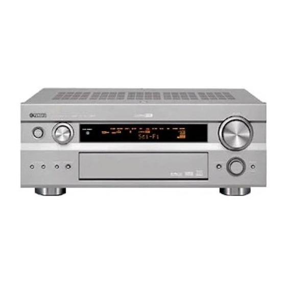
Yamaha RX-V2500 Owner's Manual
Yamaha rx-v2500: owners manual
Hide thumbs
Also See for RX-V2500:
- Owner's manual (107 pages) ,
- Product catalog (44 pages) ,
- Service manual (119 pages)
Table of Contents
Advertisement
Quick Links
Advertisement
Table of Contents

Related Manuals for Yamaha RX-V2500


Summary of Contents for Yamaha RX-V2500
- Page 1 RX-V2500 AV Receiver OWNER'S MANUAL...
-
Page 2: Important Safety Instructions
IMPORTANT SAFETY INSTRUCTIONS IMPORTANT SAFETY INSTRUCTIONS CAUTION RISK OF ELECTRIC SHOCK DO NOT OPEN CAUTION: TO REDUCE THE RISK OF ELECTRIC SHOCK, DO NOT REMOVE COVER (OR BACK). NO USER-SERVICEABLE PARTS INSIDE. REFER SERVICING TO QUALIFIED SERVICE PERSONNEL. • Explanation of Graphical Symbols The lightning flash with arrowhead symbol, within an equilateral triangle, is intended to alert you to the presence of uninsulated “dangerous voltage”... - Page 3 This product, when installed as indicated in the instructions contained in this manual, meets FCC requirements. Modifications not expressly approved by Yamaha may void your authority, granted by the FCC, to use the product. 2 IMPORTANT: When connecting this product to accessories and/or another product use only high quality shielded cables.
- Page 4 YAMAHA will not be held responsible for any damage resulting from use of this unit with a voltage other than specified.
-
Page 5: Table Of Contents
INTRODUCTION FEATURES... 2 GETTING STARTED... 3 Supplied accessories ... 3 Installing batteries in the remote controls... 3 CONTROLS AND FUNCTIONS ... 4 Front panel ... 4 Remote control... 6 Using the remote control ... 8 Front panel display ... 9 Rear panel ... -
Page 6: Features
We Want You Listening For A Lifetime YAMAHA and the Electronic Industries Association’s Consumer Electronics Group want you to get the most out of your equipment by playing it at a safe level. One that lets the sound come through loud and clear without annoying blaring or distortion –... -
Page 7: Getting Started
Supplied accessories Please check that you received all of the following parts. Remote control Batteries (4) (AAA, LR03) SYSTEM POWER POWER STANDBY POWER INPUT MODE SLEEP PHONO TUNER MULTI CH IN V-AUX CBL/SAT MD/TAPE CD-R VCR 1 DVR/VCR2 SELECT Speaker terminal wrench SOURCE TV VOL –... -
Page 8: Controls And Functions
CONTROLS AND FUNCTIONS CONTROLS AND FUNCTIONS Front panel INPUT PURE DIRECT STANDBY CBL/SAT SPEAKERS MULTI CH INPUT MODE INPUT 1 STANDBY/ON Turns on this unit or sets it to the standby mode. When you turn on this unit, you will hear a click and there will be a 6 to 7 second delay before this unit can reproduce sound. - Page 9 B MULTI CH INPUT Selects the source connected to the MULTI CH INPUT jacks. When selected, the MULTI CH INPUT source takes priority over the source selected with INPUT (or the input selector buttons on the remote control). C INPUT MODE Sets the priority (AUTO, DTS, ANALOG) for the type of signals received when one component is connected to two or more of this unit’s input jacks (see page 39).
-
Page 10: Remote Control
CONTROLS AND FUNCTIONS Remote control This section describes the function of each control on the remote control used to control this unit. To operate other components, see “REMOTE CONTROL FEATURES” on page 66. POWER POWER STANDBY INPUT MODE PHONO TUNER MULTI CH IN V - AUX CBL/SAT... - Page 11 I MULTI CH IN Selects MULTI CH INPUT when using an external decoder (etc.). J SELECT k/n Selects another component that you can control independently of the input component selected with the input selector buttons. K VOL +/– Increases or decreases the volume level. L AMP/SOURCE/TV Selects the component you want to control with the remote control.
-
Page 12: Using The Remote Control
CONTROLS AND FUNCTIONS Using the remote control The remote control transmits a directional infrared beam. Be sure to aim the remote control directly at the remote control sensor on the main unit during operation. INPUT PURE DIRECT STANDBY SOURCE PRESET/ /REMOTE A/B/C/D/E TUNING... -
Page 13: Front Panel Display
Front panel display V–AUX DVR/VCR2 VCR 1 NIGHT MATRIX VIRTUAL DISCRETE DIGITAL ZONE2 ZONE3 ZONE4 PL x SLEEP (U.S.A., Canada, U.K., Europe and Australia models only) 1 Decoder indicators When any of this unit’s decoders function, the respective indicator lights up. 2 Sound field indicators Light to indicate the active DSP sound fields. - Page 14 CONTROLS AND FUNCTIONS L 96/24 indicator Lights up when a DTS 96/24 signal is input to this unit. M LFE indicator Lights up when the input signal contains an LFE signal. N Input channel indicators Indicate the channel components of current digital input signal.
-
Page 15: Rear Panel
Rear panel DIGITAL OUTPUT TUNER VIDEO OPTICAL S VIDEO VIDEO MD/TAPE FM ANT CD-R 75Ω UNBAL. CBL/ VCR 1 COMPONENT VIDEO CBL/SAT DVR/VCR 2 CBL/ ZONE 2 MONITOR DVR/ VCR 2 MONITOR COAXIAL DIGITAL INPUT 1 DIGITAL OUTPUT jacks See page 21 for details. 2 Antenna terminals See page 23 for connection information. -
Page 16: Speaker Setup
Ideally, they should be positioned at the same width as the front speakers. Subwoofer The use of a subwoofer, such as the YAMAHA Active Servo Processing Subwoofer System, is effective not only for reinforcing bass frequencies from any or all channels,... -
Page 17: Speaker Connections
Di-pole speaker layout Either di-pole or direct radiating speaker types can be used for THX surround. If you choose di-pole speakers, please place the surround and surround back speakers according to the speaker layout below. 30˚ 30˚ :Di-pole speaker :Direction of di-pole speaker Speaker connections Be sure to connect the left channel (L), right channel (R), “+”... - Page 18 SPEAKER SETUP Tighten the knob to secure the wire. Speaker terminal wrench Red: positive (+) Black: negative (–) Connecting to PRESENCE/ZONE 2 or PRESENCE speaker terminals Open the tab. Insert one bare wire into the hole of each terminal. Return the tab to secure the wire. Banana plug connections (With the exception of U.K., Europe and Asia models) First, tighten the knob and then insert the banana plug...
- Page 19 Speaker layout (U.S.A. model) • You can connect both surround back and presence speakers to this unit, but they do not output sound simultaneously.You can set to prioritize either set of speakers in the Sound menu (see page 57). • The surround back speakers output the surround back channel included in Dolby Digital EX and DTS ES software and only operate when the Dolby Digital EX, DTS ES or Dolby Pro Logic IIx decoder is turned on.
- Page 20 SURROUND terminals Connect surround speakers to these terminals. SUBWOOFER jack Connect a subwoofer with a built-in amplifier, such as the YAMAHA Active Servo Processing Subwoofer System, to this jack. SURROUND BACK terminals Connect surround back speakers to these terminals. If you only connect one surround back speaker, connect it to the left (L) terminals.
-
Page 21: Connections
Before connecting components CAUTION Do not connect this unit or other components to the mains power until all connections between components are complete. Cable indications For analog signals left analog cables right analog cables For digital signals optical cables coaxial cables For video signals video cables S-video cables... -
Page 22: Connecting Video Components
CONNECTIONS Connecting video components Connections for DVD playback Coaxial out Optical out MONITOR (U.S.A. model) Audio out Video out DVD player VIDEO S VIDEO VIDEO COMPONENT VIDEO MONITOR AUDIO Video monitor Video in ZONE 3 OUTPUT... - Page 23 Connecting to the MULTI CH INPUT jacks This unit is equipped with 6 additional input jacks (left and right FRONT, CENTER, left and right SURROUND and SUBWOOFER) for discrete multi-channel input from a multi-format player, external decoder, sound processor or pre- amplifier.
- Page 24 CONNECTIONS Connections for other video components Optical out CBL/SAT DVR/ VCR 2 COAXIAL DIGITAL INPUT VIDEO AUX jacks (on the front panel) Use these jacks to connect any video source, such as a game console or camcorder, to this unit. Audio out Cable TV or satellite tuner...
-
Page 25: Connecting Audio Components
Connecting audio components Connections for audio components Optical in CD recorder Audio in DIGITAL OUTPUT OPTICAL MD/TAPE CD-R DIGITAL INPUT (U.S.A. model) Connecting a turntable PHONO jacks are for connecting a turntable with an MM or high-output MC cartridge. If you have a turntable with a low-output MC cartridge, use an in-line boosting transformer or MC-head amplifier when connecting to these jacks. -
Page 26: Connecting To An External Amplifier
2 SURROUND PRE OUT jacks Surround channel line output jacks. 3 SUBWOOFER PRE OUT jack Connect a subwoofer with built-in amplifier, such as the YAMAHA Active Servo Processing Subwoofer System, to this jack. 4 SURROUND BACK/PRESENCE PRE OUT jacks Surround back or presence channel line output jacks. If you only connect one external amplifier for the surround back channel, connect it to the left (L) jack. -
Page 27: Connecting The Antennas
• A property installed outdoor antenna provides clearer reception than an indoor one. If you experience poor reception quality, an outdoor antenna may improve the quality. Consult the nearest authorized YAMAHA dealer or service center about outdoor antennas. 75-ohm/300-ohm antenna adapter (U.K. -
Page 28: Connecting The Power Cable
CONNECTIONS Connecting the power cable AC OUTLETS (U.S.A. model) VOLTAGE SELECTOR (General model) Connecting the AC power cable Plug the power cable into the AC inlet after all other connections are complete, then plug the power cable to an AC wall outlet. CAUTION Do not use other AC power cables. -
Page 29: Speaker Impedance Setting
Speaker impedance setting Be sure this unit is in the standby mode. On the front panel, while holding down STRAIGHT/EFFECT, press STANDBY/ON. “SP IMP.–8 MIN” appears on the front panel display. STRAIGHT STANDBY EFFECT S P I M P . - 8 M I N Press STRAIGHT/EFFECT to select the impedance of your speakers. -
Page 30: Auto Setup
AUTO SETUP Introduction This receiver employs YAMAHA Parametric Room Acoustic Optimizer (YPAO) technology which lets you avoid troublesome listening-based speaker setup and achieves highly accurate sound adjustments. The supplied optimizer microphone collects and analyzes the sound your speakers produce in your actual listening environment. -
Page 31: Starting The Setup
Starting the setup For best results, make sure the room is as quiet as possible during the auto setup procedure (YPAO). If there is too much ambient noise, the results may not be satisfactory. If your subwoofer can adjust the output volume and the crossover frequency, set the volume to about half way (or slightly less) and set the crossover frequency to the maximum. - Page 32 AUTO SETUP For Equalizing, press k/n to select: Skip To skip the selected item and perform no adjustments. Check: Natural To average out the frequency response of all speakers with higher frequencies being less emphasized. Recommended if the “Flat” setting sounds a little harsh. Check: Flat To average the frequency response of all speakers.
-
Page 33: Confirming The Results
Confirming the results You can confirm the results of each analysis. If you set Setup Type to Auto. The results are displayed after all items have been analysed. Retry Setup Menu Exit Setup Type Setup Start Measurement Over Successfully • Press n and select Setup to set the measured values. •... - Page 34 AUTO SETUP Troubleshooting for the auto setup procedure Before auto setup Error message Connect MIC! Optimizer microphone is not connected. Unplug Phones! Headphones are connected. No Setup Menu! No setup menu items have been selected. Memory Guard! This setting is protected. During auto setup Press l / h to display detailed information for individual errors.
- Page 35 After auto setup The following warning messages are displayed after analysis is complete to inform you of possible problems. We recommend that you check the contents of each message, then select Retry to try the auto setup procedure again. Warning message W1:Out of Phase Speaker polarity is incorrect.
-
Page 36: Playback
PLAYBACK Basic operations INPUT PURE DIRECT STANDBY SOURCE PRESET/ PRESET TUNING /REMOTE A/B/C/D/E TUNING /TUNING FM/AM MEMORY MODE MD/TAPE D–TV CD–R SPEAKERS MULTI CH INPUT MODE CBL/SAT TUNER EDIT MAN'L/AUTO FM AUTO/MAN'L MONO INPUT VCR 1 SILENT CINEMA S VIDEO VIDEO /VCR2 YP AO... -
Page 37: Selecting Sound Field Programs
Select a sound field program if desired. Use PROGRAM (or press one of the sound field program buttons repeatedly) to select a sound field program. See page 45 for details about sound field programs. STEREO PROGRAM Front panel Remote control Note When this unit detects Dolby Digital signals, the following display appears for a few seconds. -
Page 38: Additional Operations
PLAYBACK Remote control operation SOURCE AMP/SOURCE/TV TV VOL – – – A / B / C / D / E TV MUTE TV INPUT MUTE PURE DIRECT EXIT TITLE MENU NIGHT ENTER AUDIO STRAIGHT RETURN DISPLAY EFFECT STEREO MUSIC ENTERTAIN MOVIE Sound field program buttons... - Page 39 Selecting the MULTI CH INPUT Press MULTI CH INPUT so that “MULTI CH INPUT” appears in the front panel display and video monitor. MULTI CH INPUT Front panel Note When “MULTI CH INPUT” is shown on the front panel display and/or the video monitor, no other source can be played.
- Page 40 PLAYBACK Enjoying 2-channel software in surround Signals input from 2-channel sources can also be played back on multiple channels. Set AMP/SOURCE/TV to AMP, then press STANDARD on the remote control to switch between the SUR. STANDARD and SUR. ENHANCED programs. STANDARD Or press MOVIE or THX on the remote control to select the MOVIE THEATER or THX programs.
- Page 41 Listening to high fidelity stereo sound (PURE DIRECT) PURE DIRECT bypasses this unit’s decoders and DSP processors as well as shuts down the video circuitry, allowing you to enjoy the highest possible sound fidelity from analog and PCM sources. Press PURE DIRECT to activate pure direct. The button lights up and the front panel display automatically goes out PURE DIRECT...
-
Page 42: Virtual Cinema Dsp
PLAYBACK Downmixing to 2 channels You can enjoy 2-channel stereo playback from multi- channel sources. Rotate PROGRAM (or press STEREO on the remote control) to select 2ch Stereo. STEREO PROGRAM Front panel 2 c h S t e r e o Note You can use a subwoofer with this program when SWFR or Both is selected in Bass Out. -
Page 43: Selecting Input Modes
Selecting input modes This unit comes with a variety of input jacks. Do the following to select the type of input signal you want to use. Select the input source. PHONO INPUT V-AUX Front panel Press INPUT MODE to select an input mode. In most cases, use AUTO. -
Page 44: Tuning
TUNING Automatic and manual tuning There are 2 tuning methods; automatic and manual. Automatic tuning is effective when station signals are strong and there is no interference. Automatic tuning INPUT PURE DIRECT STANDBY SOURCE PRESET/ PRESET TUNING /REMOTE A/B/C/D/E TUNING /TUNING FM/AM MEMORY... -
Page 45: Presetting Stations
Presetting stations Automatically presetting FM stations You can use the automatic preset tuning feature to store FM stations. This function enables this unit to automatically tune into FM stations with strong signals, and to store up to 40 (8 stations in 5 groups, A1 through E8) of those stations in order. - Page 46 TUNING Manually presetting stations You can also store up to 40 FM or AM stations (8 stations in 5 groups, A1 through E8) manually. INPUT PURE DIRECT STANDBY SOURCE PRESET/ PRESET TUNING /REMOTE A/B/C/D/E TUNING /TUNING FM/AM MEMORY MODE MD/TAPE D–TV CD–R SPEAKERS...
-
Page 47: Selecting Preset Stations
Selecting preset stations You can tune any desired station simply by selecting the preset station number under which it was stored. INPUT PURE DIRECT STANDBY SOURCE PRESET/ PRESET TUNING /REMOTE A/B/C/D/E TUNING /TUNING FM/AM MEMORY MODE MD/TAPE CD–R D–TV SPEAKERS MULTI CH INPUT MODE CBL/SAT... -
Page 48: Recording
RECORDING You can use the REC OUT/ZONE 2 or REC OUT control to record one source while watching and/or listening to another source. Recording adjustments and other operations are performed from the recording components. Refer to the operation instructions for those components. INPUT PURE DIRECT STANDBY... -
Page 49: Sound Field Program Descriptions
The YAMAHA CINEMA DSP modes are compatible with all Dolby Digital, DTS, and Dolby Surround sources. Set the input mode to AUTO (see page 39) to enable this unit to automatically switch to the appropriate digital decoder according to the input signal. -
Page 50: Dolby Digital
SOUND FIELD PROGRAM DESCRIPTIONS Program THX processing for any 5.1 channel source. THX Surr. EX DOLBY DIGITAL Standard 5.1 channel processing for Dolby Digital sources. SUR. STANDARD DOLBY DIGITAL CINEMA DSP enhanced processing for Dolby Digital sources. SUR. ENHANCED D+PLIIxMovie Standard 7.1 channel processing for Dolby Digital sources. - Page 51 Program PRO LOGIC Standard processing for Dolby Surround sources. SUR. STANDARD PRO LOGIC CINEMA DSP enhanced precessing for Dolby Surround sources. SUR. ENHANCED PLIIx Movie Dolby Pro Logic IIx processing for movie software. SUR. STANDARD PLIIx Movie CINEMA DSP enhanced precessing (Dolby Pro Logic IIx) for movie software. SUR.
-
Page 52: For Music Sources
SOUND FIELD PROGRAM DESCRIPTIONS For music sources You can select from the following sound fields when playing music sources, like CD, FM/AM broadcasting, tapes, etc. Program STEREO 2 (left and right) channel playback. 2ch Stereo STEREO Use to increase the output stereo sources (in stereo) from all speakers. This provides a larger sound field and is ideal for background music at parties, etc. -
Page 53: Advanced Operation
Using the sleep timer Use this feature to automatically set this unit in the standby mode after a certain amount of time. The sleep timer is useful when you are going to sleep while this unit is playing or recording a source. The sleep timer also automatically turns off any external components connected to the AC OUTLET(S). -
Page 54: System Options
SYSTEM OPTIONS You can use the following parameters to adjust a variety of system settings and customize the way this unit operates. Change the initial settings (indicated in bold under each parameter) to reflect the needs of your listening environment. Stereo/Surround (Stereo/Surround) Use to edit sound field parameters (see page 86). - Page 55 Option (Option) Use to adjust the optional system settings. Item Display Adjusts the GUI and front panel displays. Multi Zone Customizes the Zone 2, Zone 3 and Zone B settings. Surr.Initialize Initializes the parameters of all or a group of sound field programs. Input Mode Selects the initial input mode of the source.
-
Page 56: Changing Parameter Settings
SYSTEM OPTIONS Changing parameter settings Use the remote control to access and adjust each parameter. SOURCE TV VOL – – – A / B / C / D / E TV MUTE TV INPUT MUTE EXIT PURE DIRECT TITLE MENU NIGHT ENTER AUDIO... -
Page 57: Input Select
Input Select Use this feature to reassign digital input/outputs, select the input signal, rename the inputs, or adjust the level of the signal input to each jack. Set AMP/SOURCE/TV to AMP. SOURCE Press TOP on the remote control. Select Input Select, then press h. CD-R Stereo/Surround MD/TAPE... - Page 58 SYSTEM OPTIONS Rename (Rename) Use this feature to change the name of the inputs on the GUI and front panel display. (DVD is used as the source component in the following example.) Input Select > input source (DVD, etc.) > Rename Press an input selector button to select the input you want to change the name of.
-
Page 59: Manual Setup: Sound
Manual setup: Sound Use this menu to adjust the sound parameters. Set AMP/SOURCE/TV to AMP. SOURCE Press TOP on the remote control. Select Manual Setup, then press h. LFE Level Dynamic Range Sound Parametric EQ Basic Tone Control Option Audio Option Select Sound, then press h. - Page 60 SYSTEM OPTIONS Parametric EQ (Parametric equalizer) Use this feature to adjust the PEQ for any speaker. LFE Level Dynamic Range Parametric EQ Test Tone Tone Control Front L Audio Option Front R Press k / n to select Test Tone or the speaker you want to adjust.
- Page 61 Bass (Bass control) Use this feature to adjust low-frequencies output to your speakers or headphones. Choices: –6 to +6 (dB), Initial: 0 dB You can adjust three frequency bands: 125Hz, 350Hz, 500Hz. Speaker Freq : 125Hz Control Gain : 0.0dB Bass Treble Treble (Treble control)
-
Page 62: Manual Setup: Basic
SYSTEM OPTIONS Manual setup: Basic Use this menu to set up basic system parameters. Set AMP/SOURCE/TV to AMP. SOURCE Press TOP on the remote control. Select Manual Setup, then press h. Sound Test Tone Basic Speaker Set Option Speaker Distance Speaker Level Select Basic, then press h. - Page 63 Surround (Surround left/right speakers) Choices: Large, Small, None Front Large Center Surround Small Surround Back None Presence • Select “Large” if you have large surround left and right speakers or if a rear subwoofer is connected to the surround speakers. The entire range of the surround channel signal is directed to the surround left and right speakers.
- Page 64 SYSTEM OPTIONS Presence (Presence speakers) Choices: None, Yes Surround Surround Back Presence None Bass Out Bass Cross Over • Select “None” if you do not have presence speakers. This unit directs all presence channel signals to the front left and right speakers. •...
- Page 65 Speaker Distance (Speaker distance) Use this feature to manually input the distance of each speaker and adjust the delay applied to the respective channel. Ideally, each speaker should be the same distance from the main listening position. However, this is not possible in most home situations.
-
Page 66: Manual Setup: Option
SYSTEM OPTIONS Manual setup: Option This menu adjusts the optional system settings. Set AMP/SOURCE/TV to AMP. SOURCE Press TOP on the remote control. Select Manual Setup, then press h. Select Option then press h. Sound Display Basic Multi Zone Option Surr.Initialize Input Mode Memory Guard... - Page 67 Multi Zone (Multi zone) Use this feature to customize the Zone 2 and Zone B settings. Manual Setup > Option > Multi Zone > Speaker B Display Zone2 Amplifier Multi Zone Surr.Initialize Zone2 Volume Input Mode Zone 3 Volume Speaker B (Speaker B) Use this feature to select the location of the front speakers connected to the SPEAKERS B terminals.
-
Page 68: System Memory
SYSTEM OPTIONS Input Mode (Input mode) Use this feature to designate the input mode for sources connected to the DIGITAL INPUT jacks when you turn on this unit. Manual Setup > Option > Input Mode Choices: Auto, Last Multi Zone Surr.Initialize Input Mode Auto... - Page 69 To recall settings Set AMP/SOURCE/TV to AMP. SOURCE Press TOP on the remote control. Select System Memory, then press h. The Bottom Line Speaker Current SpeakerCH Memory 1 LFE Level D-Range Memory 2 Memory 3 Select Load, then press ENTER. Press k/n repeatedly to select the memory number you want to recall, then press h.
-
Page 70: Remote Control Features
In addition to controlling this unit, the remote control can also operate other audio and video components made by YAMAHA and other manufacturers. To control these other components, you must set up the remote control with the appropriate remote control codes. This remote control also has a Learn feature which allows the remote to acquire functions from other remote controls equipped with an infrared remote control transmitter. -
Page 71: Setting Remote Control Codes
Additional YAMAHA codes available are given in parentheses. Note You may not be able to operate your YAMAHA component even if a YAMAHA remote control code is preset as listed above. In this case, try setting another YAMAHA remote control code. Set AMP/SOURCE/TV to SOURCE. - Page 72 YAMAHA receivers/amplifiers (see page 78). When using multiple YAMAHA receivers/amplifiers, you may be able to operate the other components simultaneously with the default code setting. In this case, set one of the alternative codes to operate this unit separately.
-
Page 73: Programming Codes From Other Remote Controls (Learn)
• The supplied remote control does not contain all possible codes for commercially available audio and video components (including YAMAHA components). If operation is not possible with any of the remote control codes, program the new remote control function using the Learn feature (see “Programming codes from other remote controls (Learn)”) or use the remote... - Page 74 REMOTE CONTROL FEATURES Press LEARN using a ballpoint pen or similar object. “LEARN” and the selected component name (ex. “DVD”) appear alternately in the display window. LEARN Notes • Do not press and hold LEARN. If you hold it down for more than 3 seconds, the remote enters the remote control code setting mode.
-
Page 75: Changing Source Names In The Display Window
Changing source names in the display window You can change the name that appears in the display window on the remote control if you want to use a different name than the factory preset. This is useful when you have set the input selector to control a different component. -
Page 76: Using The Macro Feature
DVR/VCR2 You can turn on some components (including YAMAHA components) connected to this unit by connecting them to the AC OUTLET(S) on the rear panel of this unit. (Power control may not be synchronized with this unit depending on the component. For details, refer to the operating instructions for the connected component.) - Page 77 Macro operations Macro buttons TRANSMIT SYSTEM POWER POWER STANDBY POWER FREQ/RDS INPUT MODE SLEEP DISC SKIP PHONO TUNER MULTI CH IN MACRO V-AUX CBL/SAT MD/TAPE CD-R VCR 1 DVR/VCR2 MACRO ON/OFF Set MACRO ON/OFF to ON. Press a macro button. Notes •...
-
Page 78: Clearing Function Sets
REMOTE CONTROL FEATURES Press the buttons for the functions you want to include in the macro operation in sequence. You can set up to 10 steps (10 functions). After you have set 10 steps, “FULL” appears and the remote control automatically exits the macro mode. SYSTEM POWER POWER... -
Page 79: Clearing Individual Functions
Press CLEAR to exit from the clear mode. CLEAR Notes • “C:NG” appears in the display window if clearing was unsuccessful. In this case start over from step 3. • “ERROR” appears in the display window if you press a button not indicated in the respective step, or if you press more than one button simultaneously. -
Page 80: Clearing A Macro Function
REMOTE CONTROL FEATURES Press and hold CLEAR using a ballpoint pen or similar object, then press the button you want to clear for about 3 seconds. “C:OK” appears in the display window if clearing was successful. FREQ/RDS MODE PTY SEEK START DISC SKIP MACRO LEARN... -
Page 81: Controlling Each Component
Controlling each component Once you set the appropriate remote control codes, you can use this remote to control your other components. Note that some buttons may not correctly operate the selected component. Use the input selector buttons to select the component you want to operate. -
Page 82: Zone 2/Zone 3
Zone 2/Zone 3 connections that best meet your requirements. • Some YAMAHA models are able to connect directly to the CONTROL OUT jack on this unit. If you own these products, you may not need to use an infrared emitter. Up to six YAMAHA components can be connected as shown. -
Page 83: Remote Controlling Zone 2/Zone 3
Using this unit’s internal amplifier To use this unit’s internal amplifier, select “Internal” in Zone2 Amplifier 2 (page 63). Remote controlling Zone 2/Zone 3 The supplied remote control can be used to control Zone 2/Zone 3. You can even select the input source and control components located in the main room directly from the second/third room regardless of the listening condition in the main room. - Page 84 ZONE 2/ZONE 3 (U.S.A., CANADA, U.K., EUROPE AND AUSTRALIA MODELS ONLY) Press an input selector button to select the input source you want to listen to in the second/third room. The display window shows “2: name of selected input” or “3: name of selected input” if the remote control is in the Zone 2/Zone 3 mode.
-
Page 85: Front Panel Display Menus
FRONT PANEL DISPLAY MENUS This unit has additional menus that are displayed in the front panel display. Advanced setup menu This menu offers additional operations to adjust and customize the way this unit operates. Change the settings to reflect the needs of your listening environment. Make sure this unit is in the standby mode. -
Page 86: Front Panel Display System Options Menu
FRONT PANEL DISPLAY MENUS Front panel display system options menu This is a complimentary menu that allows you to access most GUI menu system option parameters without using a video monitor. Use the remote control to access and adjust each parameter. - Page 87 MANUAL SETUP 1 BASIC MENU Item A)SPEAKER SET FRONT;;;;SMALL CENTER;;;;;SML SURR.LR;;;;SML SURR.B;;;SMLx2 PRESENCE;;NONE BASS OUT;;SWFR SWFR C/O;;80Hz SWFR PHASE;NRM B)SP DISTANCE UNIT;;;;meters FRONT L;;;3.0m FRONT R;;;3.0m CENTER;;;;3.0m SURR L;;;;3.0m SURR R;;;;3.0m SB L;;;;;;2.1m SB R;;;;;;2.1m SWFR;;;;;;3.0m PRES L;;;;3.0m PRES R;;;;3.0m FRONT L;;;10.0 FRONT R;;;10.0 CENTER;;;;10.0...
- Page 88 FRONT PANEL DISPLAY MENUS 2 SOUND MENU Item A)LFE LEVEL SP LFE;;;;;;;0 HP LFE;;;;;;;0 B)D.RANGE SP D.R;;;;;MAX HP D.R;;;;;MAX C)TONE CON FRQ BASS FRQ.350Hz TRBL FRQ.xxkHz D)AUDIO OPTION A.MUTE;;;;MUTE A.DELAY;;;;;;0 PRch >SBch 3 INPUT MENU Item A)I/O ASSIGN C.V[A] DVD C.V[B] DTV C.V[C]CBL/SAT OUT(1)MD/TAPE...
- Page 89 4 OPTION MENU Item A)DISPLAY SET DIMMER;;;;;;;0 WALL PAPER;;ON SHORT MSG. ON V CONV.;;;;;ON B)MEMORY GUARD MEM.GUARD;;OFF C)SURR.INI PRESS DSP Key Cinema DSP D)ZONE SET SP B;;;;;;MAIN E)ZONE2 SET OUT VOL;;;VAR. ZONE2 AMP;;EXT F)ZONE3 SET OUT VOL;;;VAR. Sub-items • Adjusts the GUI and front panel displays. •...
-
Page 90: Editing Sound Field Parameters
The acoustics in your room could be changed to those of a concert hall, a dance floor, or virtually any size room at all. This ability to create sound fields at will is exactly what YAMAHA has done with the digital sound field processor. Changing parameter settings You can enjoy good quality sound with the factory preset parameters. -
Page 91: Sound Field Parameter Descriptions
SOUND FIELD PARAMETER DESCRIPTIONS You can adjust the values of certain digital sound field parameters so the sound fields are recreated accurately in your listening room. Not all of the following parameters are found in every program. DSP Level (DSP level) Function: This parameter adjusts the level of all the DSP effect sounds within a narrow range. - Page 92 SOUND FIELD PARAMETER DESCRIPTIONS Liveness (Liveness) Function: This parameter adjusts the reflectivity of the virtual walls in the hall by changing the rate at which the early reflections decay. Description: The early reflections of a source sound decay much faster in a room with acoustically absorbent wall surfaces than in one which has highly reflective surfaces.
- Page 93 Rev.Time (Reverberation time) Function: This parameter adjusts the amount of time it takes for the dense, subsequent reverberation sound to decay by 60 dB (at 1 kHz). This changes the apparent size of the acoustic environment over an extremely wide range. Description: The longer the reverberation time, the more “live”...
- Page 94 SOUND FIELD PARAMETER DESCRIPTIONS Dialogue Lift (Dialog lift) Function: This parameter adjusts the height of the front and center channel sounds by assigning some of the front and center channel elements to the presence speakers. Description: The larger the parameter, the higher the position of the front and center channel sound. Choices: 0/1/2/3/4/5, initial setting is 0.
- Page 95 Decode Type (Decoder type) For MOVIE THEATER Function: Selects the decoder used to playback 2-channel sources using MOVIE THEATER programs. Choices: Pro Logic / Pro Logic II / Pro Logic IIx / Neo:6 For THX Cinema Function: Selects the decoder used to playback 2-channel sources using THX Cinema. Choices: Pro Logic / Pro Logic II / Pro Logic IIx / Neo:6 For SURROUND Standard...
-
Page 96: Troubleshooting
Refer to the chart below when this unit does not function properly. If the problem you are experiencing is not listed below or if the instruction below does not help, set this unit to the standby mode, disconnect the power cable, and contact the nearest authorized YAMAHA dealer or service center. General... - Page 97 Problem The sound suddenly The protection circuitry has been activated goes off. because of a short circuit, etc. The sleep timer has turned the unit off. The sound is muted. Only the speaker on Incorrect cable connections. one side can be heard.
- Page 98 TROUBLESHOOTING Problem Dolby Digital or DTS The connected component is not set to sources cannot be output Dolby Digital or DTS digital played. (Dolby Digital signals. or DTS indicator on The input mode is set to “ANALOG”. the front panel display does not light up.) A “humming”...
- Page 99 Tuner Problem FM stereo reception is The characteristics of FM stereo noisy. broadcasts may cause this problem when the transmitter is too far away or the antenna input is poor. There is distortion, and There is multipath interference. clear reception cannot be obtained even with a good FM antenna.
- Page 100 TROUBLESHOOTING Remote control Problem The remote control Wrong distance or angle. does not work nor function properly. Direct sunlight or lighting (from an inverter type of fluorescent lamp, etc.) is striking the remote control sensor of this unit. The batteries are weak. AMP/SOURCE/TV is set incorrectly.
-
Page 101: Glossary
Audio formats Dolby Digital Dolby Digital is a digital surround sound system that gives you completely independent multi-channel audio. It provides 5 full-range audio channels; 3 front channels (left, center, and right), and 2 surround stereo channels. An additional channel especially for bass effects, called LFE (low frequency effect) is also provided giving the system a total of 5.1-channels (LFE is counted as a 0.1 channel). -
Page 102: Sound Field Programs
SILENT CINEMA YAMAHA has developed a natural, realistic sound effect DSP algorithm for headphones. Parameters for headphones have been set for each sound field so that accurate representations of all the sound field programs can be enjoyed on headphones. -
Page 103: Audio Information
Audio information ITU-R ITU-R is the radio communication sector of the ITU (International Telecommunication Union). ITU-R recommends a standard speaker placement which is used in many critical listening rooms, such as mastering studios. LFE 0.1 channel This channel is for the reproduction of low bass signals. The frequency range for this channel is 20 Hz to 120 Hz. -
Page 104: Video Signal Information
DVD software titles encoded with this technology can be found at www.thx.com. Only receiver and controller products bearing the THX Surround EX logo, when in the THX Surround EX mode, faithfully reproduce this new technology in the home. -
Page 105: Parametric Equalizer Information
PARAMETRIC EQUALIZER INFORMATION This unit employs YAMAHA Parametric Room Acoustic Optimizer (YPAO) technology, together with the Parametric EQ settings (see page 56), to optimize the frequency characteristics of its parametric equalizer to match your listening environment. YPAO uses a combination of the following three parameters (Frequency, Gain and Q factor) to provide highly precise adjustment of the frequency characteristics. -
Page 106: Specifications
SPECIFICATIONS AUDIO SECTION • Minimum RMS Output Power for Front, Center, Surround, Surround back 20 Hz to 20 kHz, 0.04% THD, 8 ... 130 W • Maximum Power (EIAJ) [Australia, China, Asia, Korea and General models] 1 kHz, 10% THD, 8 ... - Page 107 SOUNDESIGN 0105 AUDIO TON TECHNICS 0335 AUDIOLAB THORENS 0296 AUDIOMECA 0184 VICTOR 0358 CAIRN WARDS 0040, 0105 CALIFORNIA AUDIO LABS YAMAHA 0381 CARVER CYRUS CABLE 0030, 0035 DMX ELECTRONICS AMERICAST 0926 BELL SOUTH 0926 DENON BIRMINGHAM CABLE DYNAMIC BASS COMMUNICATIONS EMERSON...
- Page 108 VENTURER MD RECORDER VICTOR KENWOOD 0708 WARDS ONKYO 0895 YAMAHA SHARP 0888 SONY 0517 YAMAHA 2500, 2501, 2502 SATELLITE TUNER @SAT RECEIVER (TUNER) ABSAT 0558 ALBA AIWA 0185, 1116, 1415, ALPHASTAR 0799 1432, 1668 AMSTRAD ALCO 1417 ASTON ANAM 1636...
- Page 109 CIMLINE 0036 GOLDSTAR CINERAL 0119, 0478 CITIZEN 0057, 0087, 0119 GOODMANS 0064, 0398, 0401, CLARION 0207 CLARIVOX 0064 GOREMJE CLATRONIC 0274, 0397 GRADIENTE 0080, 0197 CONDOR 0347, 0397 GRAETZ CONRAC 0835 GRANADA CONTEC 0036, 0207 CRAIG 0207 GRANDIN CROSLEY 0081 GRUNDIG CROWN 0036, 0064, 0207,...
- Page 110 0064 SONY 0027, 0677, 0861, WATSON 1127, 1532, 1678 WAYCON SOUNDESIGN 0205, 0207 WHITE WESTINGHOUSE SOUNDWAVE 0064, 0445 SOWA 0078, 0087, 0119, 0183, 0205 YAMAHA SQUAREVIEW 0198 STANDARD 0036 STARLITE 0207 STERN 0190, 0286 YAPSHE SUPREME 0027 YOKO SYLVANIA 0057, 0081, 0198...
- Page 111 REPLAYTV 0641, 0643 VILLAIN 0068 WARDS ROADSTAR 0064, 0099, 0267, 0305 RUNCO 0066 WHITE WESTINGHOUSE 0108 0267 XR-1000 0108 YAMAHA 0069 YAMISHI SABA 0068, 0347 YOKAN SALORA 0070 YOKO SAMPO 0064, 0075 ZENITH SAMSUNG 0072, 0267, 0459 SANKY 0066, 0075...
- Page 112 YAMAHA ELECTRONICS (UK) LTD. YAMAHA HOUSE, 200 RICKMANSWORTH ROAD WATFORD, HERTS WD18 7GQ, ENGLAND YAMAHA SCANDINAVIA A.B. J A WETTERGRENS GATA 1, BOX 30053, 400 43 VÄSTRA FRÖLUNDA, SWEDEN YAMAHA MUSIC AUSTRALIA PTY, LTD. 17-33 MARKET ST., SOUTH MELBOURNE, 3205 VIC., AUSTRALIA...