Table of Contents
Advertisement
Quick Links
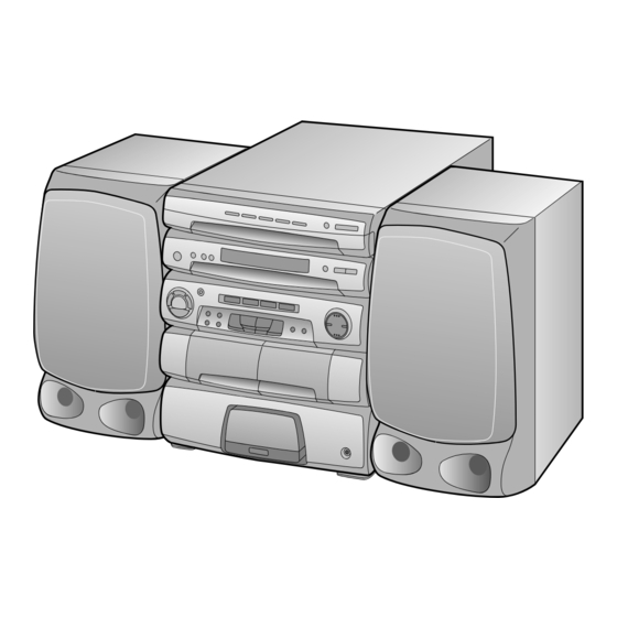
Illustration: CMS-R600X(BK)
• SRS technology Licensed from SRS Labe. SRS technology holds
the follwing patents: U.S. Patent No. 4,748,669, U.S. Patent No.
4,841,572 and U.S. Patent No. 4,866,774.
• SRS the SRS Logo (
) and the SOUND RETRIEVAL SYSTEM
are registered trademarks of SRS Labs, Inc.
SPECIFICATIONS ............................................................................................................................................................. 2
VOLTAGE SELECTION ..................................................................................................................................................... 2
NAMES OF PARTS ........................................................................................................................................................... 3
OPERATION MANUAL ...................................................................................................................................................... 5
DISASSEMBLY .................................................................................................................................................................. 6
REMOVING AND REINSTALLING THE MAIN PARTS ..................................................................................................... 8
ADJUSTMENT ................................................................................................................................................................. 10
NOTES ON SCHEMATIC DIAGRAM .............................................................................................................................. 12
TYPES OF TRANSISTOR AND LED .............................................................................................................................. 12
BLOCK DIAGRAM ........................................................................................................................................................... 13
SCHEMATIC DIAGRAM / WIRING SIDE OF P.W.BOARD ............................................................................................. 16
WAVEFORMS OF CD CIRCUIT ...................................................................................................................................... 36
LCD DISPLAY .................................................................................................................................................................. 37
TROUBLESHOOTING (CD SECTION) ........................................................................................................................... 38
FUNCTION TABLE OF IC ............................................................................................................................................... 42
REPLACEMENT PARTS LIST/EXPLODED VIEW
DIFFERENCE BETWEEN CMS-R600X(BK) AND CMS-R600XT(BK)
POWER
SOURCE
SPEAKER
SRS
SERVICE MANUAL
• In the interests of user-safety the set should be restored to its
CONTENTS
CMS-R600X(BK)
AC 110/127/220/230-240 V,
50/60 Hz
SHARP CORPORATION
CMS-R600X(BK)
CMS-R600XT(BK)
original condition and only parts identical to those specified
should be used.
CMS-R600XT(BK)
AC 220 V, 50 Hz
CMS-R600X/R600XT
No. S8644CMSR600X
Page
Advertisement
Table of Contents

Related Manuals for Sharp CMS-R600X(BK)


Summary of Contents for Sharp CMS-R600X(BK)
-
Page 1: Table Of Contents
LCD DISPLAY .................................. 37 TROUBLESHOOTING (CD SECTION) ........................... 38 FUNCTION TABLE OF IC ............................... 42 REPLACEMENT PARTS LIST/EXPLODED VIEW DIFFERENCE BETWEEN CMS-R600X(BK) AND CMS-R600XT(BK) CMS-R600X(BK) CMS-R600XT(BK) POWER AC 110/127/220/230-240 V, AC 220 V, 50 Hz SOURCE 50/60 Hz SPEAKER SHARP CORPORATION... -
Page 2: Specifications
CMS-R600X/R600XT FOR A COMPLETE DESCRIPTION OF THE OPERATION OF THIS UNIT, PLEASE REFER TO THE OPERATION MANUAL. SPECIFICATIONS General Compact disc player section Power source: AC 110/127/220/230-240 V, Type: 5-disc multi-play compact disc (CMS-R600X) 50/60 Hz player Power source: AC 220 V, 50 Hz Signal readout: Non-contact;... -
Page 3: Names Of Parts
CMS-R600X/R600XT NAMES OF PARTS Front panel 1. Disc Tray 2. Disc Number Select Buttons 3. Disc Skip Button 4. Open/Close Button: 5. Power Switch 6. (TUNER) Memory Button 7. Tuning Up/Down Buttons: 8. Timer Indicator 5 6 7 8 9. Remote Control Sensor 10. - Page 4 CMS-R600X/R600XT Rear panel 1. Speaker Terminals 2. Phono Power Supply Socket (DC 12V) (CMS-R600X ONLY) 3. AC Power Input Socket 4. AC Voltage Selector (CMS-R600X ONLY) 5. FM 75 ohns Aerial Terminal 6. Aerial Earth Terminal 7. AM Loop Aerial Socket 8.
-
Page 5: Operation Manual
PREPARATION FOR USE SETTING THE CLOCK Notes concerning use: Setting method when the POWER switch is in the STAND-BY In this example, the clock is set for the 24-hour Replace the batteries if control distance decreases or oper- position. (0:00) system. ation becomes erratic. -
Page 6: Disassembly
CMS-R600X/R600XT DISASSEMBLY Top Cabinet (A1) x 2 Caution on Disassembly ø3 x 12mm Follow the below-mentioned notes when disassembling the unit and reassembling it, to keep it safe and ensure excellent performance: (A1) x 2 1. Take cassette tape and compact disc out of the unit. ø3 x 12mm 2. - Page 7 CMS-R600X/R600XT (S1) x 2 Front Panel ø3 x 10mm (J1) x 4 Switch PWB (T1) x 1 ø3 x 10mm ø3 x 10mm Display PWB CD Servo (K1) x 9 Sensor PWB ø3 x 10mm (H1) x 1 (L1) x 1 ø3 x 8mm (T2) x 2 CD Tray...
-
Page 8: Removing And Reinstalling The Main Parts
CMS-R600X/R600XT REMOVING AND REINSTALLING THE MAIN PARTS TAPE MECHANISM SECTION TAPE 2 Record/Playback Perform steps 1, 2, 3, 4, 5 and 8 of the disassembly method to Head Erase Head remove the tape mechanism. How to remove the record/playback and erase heads (TAPE 2) (See Fig. - Page 9 CMS-R600X/R600XT CD MECHANISM SECTION Perform steps 1, 2, 3, 14, 15 and 16 of the disassembly method to remove the CD mechanism. ( A1 ) x2 ø2.6 x5mm How to remove the loading motor (See Fig. 9-1) 1. Remove the screws (A1) x 2 pcs., to remove the loading Loading Motor motor.
-
Page 10: Adjustment
CMS-R600X/R600XT ADJUSTMENT TAPE MECHANISM SECTION • FM RF Signal generator: 1 kHz, 75 kHz dev., FM modulated • Driving Force Check Test Stage Frequency Frequency Serring/ Instrument Torque Meter Specified Value Display Adjusting Connection Play: TW-2412 Tape 1: Over 50 g Point Tape 2: Over 100 g Band... - Page 11 CMS-R600X/R600XT CD SECTION CD TEST MODE When the CD, STOP and POWER keys are Since this CD system incorporates the following automatic pressed at the same time, to turn on the power, adjustment function, when the pickup is replaced, it is not the unit will enter the test mode.
-
Page 12: Notes On Schematic Diagram
CMS-R600X/R600XT NOTES ON SCHEMATIC DIAGRAM • The indicated voltage in each section is the one measured • Resistor: by Digital Multimeter between such a section and the chas- To differentiate the units of resistors, the symbol as K and M sis with no signal given. - Page 13 IC51, IC52 : MOTOR DRIVER CHANGER MECHA IC51 LOADING TA7291S MOTOR PICKUP UNIT IC52 TURNTABLE 16.93MHz TA7291S UP/DOWN DISC UP SW VCC1 XOUT CONT1 DISC NO. DEFI SENSOR DEF/THLD CONT5 EFMO EFMIN CLV+ (OPEN) LCHO L-CH OUT AUDIO GND FIN2 JP–...
-
Page 14: Block Diagram
CMS-R600X/R600XT SO301 ANTENNA FM FRONT END TERMINAL FM IF AM IF CF352 IC301 CF302 FM 75ohms TA7358AP T351 CF351 AM IF AM MIX FM DET IC351 L303 L OUT OSC. LA1832 R OUT FM RF FM IF DET. /FM MPX. /AM IF L302 T301 FM IF... - Page 15 CMS-R600X/R600XT EDGE LAMP LMP561 LCD701 Q481 DISPLAY BACK LAMP LMP801 REMOTE CONTROL COM 0 ~ COM 3 S0 ~ S31 SENSOR SWITCHING REMOTE IN Q482 RX701 XL702 32.768kHz LMP802 LCD BIAS D702 Q483 14 50 ILLUNIMATION GUIDE LED DRIVER +B3 (5V BACK UP) COM OUT +5.7V UN SWITCH...
-
Page 16: Schematic Diagram / Wiring Side Of P.w.board
CMS-R600X/R600XT P21 9 - H TO DISPLAY PWB CD PWB-C1 FC700 CNP10 1 3 5 7 9 11 13 15 17 19 2 4 6 8 10 12 14 16 18 20 CNP80 R58 R62 E C B 16 17 ZD81 LNGR R100... - Page 17 CMS-R600X/R600XT SUB PWB-C2 COLOR TABLE BROWN VIOLET R D ( R ) GRAY CNP90 ORANGE W H ( W ) WHITE YELLOW BLACK GREEN PINK BLUE CNS80B LOADING MOTOR TURNTABLE UP/DOWN DISC UP CNS80A CNS5 TO POWER PWB CNP901 P32 3 - A PICKUP UNIT CD MOTOR PWB-D SPIN MOTOR...
- Page 18 CMS-R600X/R600XT KTA1266 GR 47/10 4.9V 0.33/50 0.01 0.01 4.7K FIN2 + – – FIN1 – 2.5V – – – EFBAL 4.7/25 0.1/50 FOSTA – TOSTA – + DGND TE– 2FREQ – 100K – + LASER – + FSTA 0.001 8/120M 2.2K LA9240M 0.033...
- Page 19 CMS-R600X/R600XT CD PWB-C1 CD SIGNAL 100P 100P 100P 4.7K 100P 0.01 4.7/25 EFLG SBSY µ-COM SUB-CODE DEFI INTERFACE XVSS 16.93MHz 2.2M X-TAL LC78622E GENERATOR XOUT 0.033 SERVO/SIGNAL 0.047 CONTROL VVSS XVDD 0.001 ISET MUTER CNS10 0.047 RVDD 10/16 RCHO 220P 5.6K ERROR VVDD...
- Page 20 CMS-R600X/R600XT R719 R717 R718 OPEN/CLOSE FW703 SW708 SW707 SW705 SW706 DISC SKIP DISC 5 DISC 4 LCD701 R738 Q710 R740 RX701 Q709 R742 R701 FW703 R703 R702 DOWN BAND R829 SW726 SW734 Q701 E C B TUNER C712 SW718 PRESET R704 TIME C713...
- Page 21 CMS-R600X/R600XT SWITCH PWB-B2 R716 R715 R714 P25 10 - A SW704 TO MAIN PWB SW702 DISC 3 SW703 DISC 1 DISC 2 CNP432 LCD701 R705 R713 Q716 R712 R710 R721 LED705 TUNING TUNING R722 R711 DOWN MEMORY SW714 SW715 SW722 R724 R725 R752...
- Page 22 CMS-R600X/R600XT 4.3V 4.9V 4.3V 4.3V 36 35 34 33 32 31 30 29 28 27 26 25 24 23 22 21 20 19 18 17 16 15 14 13 12 11 10 9 8 7 6 5 4.3V R705 4.9V R706 R707 R708...
- Page 23 CMS-R600X/R600XT DISPLAY PWB-B1 CD SIGNAL CD CHANGER OPEN CLOSE LCD701 SW801 CNP701 CNS701 FC700 CNP700 8 17 16 15 14 13 12 11 10 9 8 7 6 5 4 3 2 1 DISC UP LMP801 PUIN DISC NO. R705 SENSOR LMP802 SLDM+...
- Page 24 CMS-R600X/R600XT AM LOOP ANTENNA Q302 IC381 SO301 BF301 BF301 ANTENNA C390 TERMINAL 22 20 L381 C386 R386 R389 IC301 R387 C328 C389 R390 FM 75ohms C387 R312 T351 CF351 T301 L302 VR351 C314 R320 C364 600X FM MUTE C363 Q372 ONLY LEVEL D303...
- Page 25 CMS-R600X/R600XT P21 12 - B TO DISPLAY PWB MAIN PWB-A1 CNS702 C483 R435 R431 R433 CNP432 600X R439 600X ONLY ONLY IC501 FW501 9 C434 C438 Q504 FW501 IC431 600X 600X ONLY ONLY R452 49 50 600X:JUMPER 600XT:D432 D431 CNP431 R454 SRS PWB-E 3 2 1...
- Page 26 CMS-R600X/R600XT C421 600X : 270P 600X ONLY SO401 R425 R421 600XT : 100P FM SIGNAL L-CH 600XT ONLY C421 PLAYBACK SIGNAL VIDEO/AUX L421 C422 RECORD SIGNAL 0.82µH 270P R-CH R426 R422 CD SIGNAL 600X ONLY 600X ONLY PHONO VIDEO/AUX SIGNAL SW421-A C423 VIDEO/ AUX...
- Page 27 CMS-R600X/R600XT MAIN PWB-A1(1/3) R449 600X : 15K 600XT : 12K 600X ONLY C437 1/50 C439 22/16 R449 C443 C447 C449 C451 C455 C457 C445 C453 0.0022 0.47/50 0.056 0.22/50 0.01 1/50 0.047 0.056 R443 C431 1/50 R435 C463 LVREF R441 C433 100P 1/50...
- Page 28 CMS-R600X/R600XT FM SIGNAL AM SIGNAL FM FRONT END BAND PASS FILTER IC301 BF301 TA7358AP SO301 B. A T351 ANTENNA TERMINAL AM IF FM 75ohms C328 C312 C315 R314 C322 10/16 0.01 C352 C317 0.022 AM LOOP FM OSC 4.7P ANTENNA C323 C318 R316...
- Page 29 CMS-R600X/R600XT R365 CF351 L355 C374 100µH 0.022 R366 C363 100/6.3 R364 T351 5.6K AM IF C364 C352 C367 0.022 R359 2.2/50 3.3K C372 0.022 R356 C368 1/50 Q371 D351 R352 KTC3199 GR 5.6K 1SS133 R379 FM MUTE C373 LEVEL 3.3/50 R361 24 23 22 21 20 19 18...
- Page 30 CMS-R600X/R600XT PLAYBACK SIGNAL RECORD SIGNAL MAIN PWB-A1(2/3) R242 R237 ) : REC. MARKING EXCEPT FOR( ) : PLAY. TAPE1 R201 Q201 PLAYBACK HEAD KRC104 M C205 R240 R239 560P 5.6K (0V) L-CH (0V) HI. SP C253 R241 C225 22/16 (0V) 0.001 0V(0V) (0V)
- Page 31 CMS-R600X/R600XT R271 T1/T2 R242 R237 R256 HI. SPEED 100K REC R REC L Q212 R255 KTC3199 GR 100K PRE L PRE R P. B. MUTE PB. MUTE R272 R246 (0V) (0V) R240 R239 BIAS 0.7V (0V) 0.7V (0.7V) (0.7V) 5.6K Q255 (0V) (0V)
- Page 32 CMS-R600X/R600XT P17 8 - D TO CD SERVO CNS5 TO TAPE MECHANISM D650 WIRE LUG(254) D651 LUG601 C924 R925 B C E Q931 ZD921 R941 D921 R940 R928 R923 TO MAIN PWB B C E 1 2 3 Q930 WT921 P25 8 - E R930 C927...
- Page 33 FM SIGNAL IC601 POWER PWB-A2 HEADPHONES PWB-A3 TO TAPE MECHANISM C621 VOLTAGE D651 R613 LUG 601 1SS133 C652 0.01 C603 R611 (ML) D603 –27V +IN A OUT A D650 1SS133 CHASSIS 1SS133 R607 6.3V R603 C609 D602 600X : 82K FW601 R605 0.22...
- Page 34 IC561, IC562 : METER DRIVER L563 330µH IC561 IC562 R565 R572 R566 R571 C569 LB1403N LB1403N 330/16 LED561 R561 LED562 FW561 5N4KTN52 5N4KTN52 L IN C561 LED563 0.22/50 LED564 R IN 5N4KTN52 5N4KTN52 R562 TO MAIN PWB C562 0.22/50 WT701 LED565 LED566 5N4KTN52...
- Page 35 RECORD SIGNAL WT501 L-OUT R-OUT Q504 Q502 +12V KRC102M 2SK246GR TO MAIN PWB A GND FW501 R531 R556 R-IN P27 11 - G R557 R558 VREF L-IN PASS SRS 1 C506 0.001 C505 R533 0.001 Q506 C557 KRC102M 2.2/50 C554 C502 R502 0.22(ML)
-
Page 36: Waveforms Of Cd Circuit
CMS-R600X/R600XT WAVEFORMS OF CD CIRCUIT STOP PLAY FOCUS SERCH 0.5ms 0.50 V 10.0 V IC1 20 F.E 0.5ms 10.0 V 0.5ms 5.0 V 0.50 V IC1 54 DRF 0.5ms 1.00 V 0.5ms PLAY 1.00 V NORMAL DISC TN0=01 20ms 1.00 V 0.5ms 5.0 V 20ms... -
Page 37: Lcd Display
CMS-R600X/R600XT LCD701 : RV-LX0019AWZZ LCD Display COMMON SEGMENT – 37 –... -
Page 38: Troubleshooting (Cd Section)
CMS-R600X/R600XT TROUBLESHOOTING (CD SECTION) When the CD does not function When the CD section does not operate When the objective lens of the optical pickup is dirty,this section may not operate.Clean the objective lens,and check the playback operation.When this section does not operate even after the above step is taken,check the following items. - Page 39 CMS-R600X/R600XT • When the CD tray fails to open or close. Is there following voltage input in specific state of IC701 pin Check the wiring of the IC2 pins 24 and 25, IC91 pins 1 and 3. 46 and 47 pin? Open state: 0V (IC701 pin 47) Close state: 0V (IC701 pin 46) Intermediate state between open state and close state: 5V...
- Page 40 CMS-R600X/R600XT • Playback can only be performed when a disc is loaded. Check the laser diode driver. Is the Focus servo active? (Can you hear it working?) Check the area around IC1(16) - (21) (focus servo circuit). If the disc is not turning, the Does the DRF signal change from "L"...
- Page 41 CMS-R600X/R600XT • Checking the spin system. Play operation is performed without disc. The turntable rotates a little. The spin driver circuit is normal. Check the periphery of IC1 pins 23 to 27, pin 39, and pin 40, IC2 The turntable fails to rotate or rotates at high speed. pin 12 and pin 13, IC5 to CNP4.
-
Page 42: Function Table Of Ic
CMS-R600X/R600XT FUNCTION TABLE OF IC IC2 VHiLC78622E-1:Servo/Signal Control (1/2) Terminal Name Input/Output Function Pin No. DEFI Input Input terminal of defect detection signal (DEF). (Connected to OV when not used.) Input For PLL Input terminal for test. Pull-down resistor is integrated. Surely connected to 0V. Output Output terminal of phase comparison for external VCO control. - Page 43 CMS-R600X/R600XT IC2 VHiLC78622E-1:Servo/Signal Control (2/2) Pin No. Terminal Name Input/Output Function Output Output terminal of subcodes P, A, R, S, T, U and W. SFSY Output Output terminal of synchronous signal of subcode frame. It drops when subcode stands by. SBCK Input Clock input terminal to read subcode.
- Page 44 CMS-R600X/R600XT IC1 VHiLA9240M/-1:Servo Amp. (1/2) Function Port Name Pin No. FIN2 Connection pin for photodiode of pickup. RF signal is generated through addition with FIN pin, and FE signal is generated through subtraction. FIN1 Connection pin for photodiode of pickup. Connection pin for photodiode of pickup.
- Page 45 CMS-R600X/R600XT IC1 VHiLA9240M/-1:Servo Amp. (2/2) Function Pin No. Port Name Micro computer command clock input pin. Micro computer command data input pin. Micro computer command chip enable input pin. (DETECT RF) RF level detection output. (Focus Serch Select) Pin to switch focus search mode. (± search/+ search for reference voltage) VCC2 VCC pin for servo system and digital system.
- Page 46 CMS-R600X/R600XT IC701 RH-iX0153AWZZ:System Microcomputer (1/2) Pin No. Port Name Terminal Name Input/Output Function Active B DI Output B Data output (Normal: LO) SCK0 B CK Output B Clock output (Normal: LO) SQOUT Input CD Sub-Q data input COIN Output CD System Command data output (Function "CD": H) ASCK CQCK...
- Page 47 CMS-R600X/R600XT IC701 RH-iX0132AWZZ:System Microcomputer (2/2) Pin No. Port Name Terminal Name Input/Output Function Active 60 - 91 SEG0 - 31 SEG0 - 31 Output LCD Segment driver output — ILLU GUIDE 1 Output LED Control L: ON ILLU GUIDE 2 Output LED Control L: ON...
- Page 48 CMS-R600X/R600XT IC5 VHiBA5920FP-1:Focus/Tracking/Spin/Slide Driver Function Terminal Name Pin No. VO1(-) Driver CH1 Negative output. VO1(+) Driver CH1 Positive output. VIN1 Driver CH1 input. VIN1' Input terminal to adjust driver CH1 gain. Not Used Not Used MUTE Mute control terminal. VIN2' Input terminal to adjust driver CH2 gain.
- Page 49 “HOW TO ORDER REPLACEMENT PARTS” To have your order filled promptly and correctly, please furnish the For U.S.A. only following information. Contact your nearest SHARP Parts Distributor to order. 1. MODEL NUMBER 2. REF. No. 3. PART NO. 4. DESCRIPTION For location of SHARP Parts Distributor, Please call Toll-Free;...
- Page 50 CMS-R600X/R600XT PRICE PRICE PART CODE DESCRIPTION PARTS CODE DESCRIPTION RANK RANK INTEGRATED CIRCUITS D921 VHD1SS133//-1 AA Silicon,1SS133 LED561~568 VHP5N4KTN52-1 AD LED,Green,5N4KTN52 VHILA9240M/-1 AV Servo Amp.,LA9240M LED569,570 VHP333ITR4/-2 LED,Red,333ITR4 VHILC78622E-1 BA Servo/Signal Control, LC78622E LED701~705 VHP5N4GTN52-1 AD LED,Green,5N4GTN52 VHIBA5920FP-1 AR Focus/Tracking/Spin/ Slide VHPRPI574N/-1 AN Photo Interrupter,RPi574N Driver,BA5920FP...
- Page 51 CMS-R600X/R600XT PRICE PRICE DESCRIPTION PARTS CODE DESCRIPTION PART CODE RANK RANK AA 0.47 µF,50V,Electrolytic RC-GZA474AF1H C340 VCKYMN1HB471K J AA 470 pF,50V AB 1 µF,50V,Electrolytic AA 0.022 µF,25V RC-GZA105AF1H C342 VCTYMN1EF223Z AB 47 µF,10V,Electrolytic RC-GZA476AF1A C344 VCCUMN1HJ8R2D J AA 8.2 pF (UJ),50V AA 0.0033 µF,16V AB 10 µF,16V,Electrolytic VCTYMN1CX332K J...
- Page 52 CMS-R600X/R600XT PRICE PRICE PART CODE DESCRIPTION PARTS CODE DESCRIPTION RANK RANK C546 VCCSPA1HL391J AA 390 pF,50V [600X Only] VRD-MN2BD471J AA 470 ohms,1/8W AA 0.33 µF,50V,Electrolytic C547 RC-GZA334AF1H R36,37 VRD-MN2BD473J AA 47 kohms,1/8W [600X Only] VRD-MN2BD333J AA 33 kohms,1/8W AA 0.47 µF,50V,Electrolytic C549~552 RC-GZA474AF1H R39,40...
- Page 53 CMS-R600X/R600XT PRICE PRICE DESCRIPTION PARTS CODE DESCRIPTION PART CODE RANK RANK R352 VRD-MN2BD562J AA 5.6 kohms,1/8W R609,610 VRD-MN2BD221J AA 220 ohms,1/8W [600XT] R353 VRD-MN2BD272J AA 2.7 kohms,1/8W R611,612 VRD-MN2BD223J AA 22 kohms,1/8W R354 VRD-ST2CD392J AA 3.9 kohms,1/6W R613,614 VRD-ST2CD102J AA 1 kohm,1/6W R355 VRD-MN2BD271J AA 270 ohms,1/8W...
- Page 54 CMS-R600X/R600XT PRICE PRICE PART CODE DESCRIPTION PARTS CODE DESCRIPTION RANK RANK R828 VRD-ST2CD151J AA 150 ohms,1/6W FWM1 QCNWN0333AWZZ J AD Flat Wire,4Pin R829 VRD-ST2CD103J AA 10 kohm,1/6W FWM2 QCNWN0338AWZZ J AD Flat Wire,2Pin R830 VRD-ST2CD102J AA 1 kohm,1/6W J601 QJAKJ0003AWZZ AM Jack,Headphones R831 VRD-ST2CD332J...
- Page 55 MSPRD0037AWFJ J AB Spring,Over Strok Lever (Not Replacement Item) MSPRD0038AWFJ J AB Spring,Trigger Lever 202- 2 HDECP0035AWSA J AE Decoration Plate,SHARP [600X] MSPRD0039AWFJ J AB Spring,FR Lever 202- 2 HDECP0035AWSB J AE Decoration Plate,SHARP MSPRD0040AWFJ J AB Spring,Eject Obstruct [Tape 2]...
- Page 56 CMS-R600X/R600XT PRICE PRICE PART CODE DESCRIPTION PARTS CODE DESCRIPTION RANK RANK P.W.B. ASSEMBLY (Not Replacement Item) MSPRD0070AWFP J AC Spring,Cassette (Tape 2) 92LN-BAND1318A AA Nylon Band,80mm NBLT-0017AWZZ AE Belt,Drive PWB-A1~4 92LPWB2231MANS J — Main/Power/Headphones/Spacer NGEAH0049AWFW J AE Gear,Tray Lock (Combined Ass’y) NGERH0048AWZZ J AG Pulley,Gear [600X for Australia/New...
- Page 57 CMS-R600X/600XT 305-2 305-1 305-3 PWB-F Figure 8 CD MECHANISM EXPLODED VIEW – 8 –...
- Page 58 CMS-R600X/600XT TAPE1 TAPE2 503x3 503x2 503x3 503x2 SOLM1 SWM5 501x2 SWM4 SWM3 502x2 PWB-G BELT CONNECTION (TAPE2) (TAPE1) 100mm BOTTOM VIEW Figure 9 TAPE MECHANISM EXPLODED VIEW – 9 –...
- Page 59 CMS-R600X/600XT 202-2 617x2 202-1 610x2 227-3 227-2 227-1 610x2 608x2 PWB-C2 608x2 SW801 CD MECHANISM 243x2 PWB-C1 618x2 612x2 247x3 601x2 Figure 10 CABINET EXPLODED VIEW (1/2) – 10 –...
- Page 60 CMS-R600X/600XT 614x2 614x3 PWB-B3 PWB-B1 615x2 622x8 PWB-A4 612x4 PWB-B2 612x9 201-10 201-9 LCD701 201-12 201-1 201-7 TAPE PWB-D1 201-13 MECHANISM 612x2 201-4 617x6 201-6 201-8 201-5 201-3 201-11 201-14 602x2 607x3 PWB-D2 PWB-A1 201-2 612x5 Q924 Q925 255x4 Q923 611x4 201-15 PWB-A3...
- Page 61 CMS-R600X/600XT TWEETER SP3 (L - CH) 709x4 SP4 (R - CH) BLACK BLACK SUPER TWEETER SP5 (L - CH) SP6 (R - CH) C1,2 BLACK 710x4 710x2 WHITE LINE SP1,2 SP3,4 WOOFER SP1 (L - CH) SP2 (R - CH) SP5,6 TWEETER SP3 (L - CH)
- Page 62 CMS-R600X/600XT — M E M O — – 13 –...
- Page 63 CMS-R600X/600XT — M E M O — – 14 –...
- Page 64 CMS-R600X/600XT A9608-1405NS•HA•M Printed in Japan EX • SA • SZ Writer and Editor: Quality & Reliability Control Center of Communication & Audio Systems Group, Sharp Corp.