Lenovo ThinkCentre 8289 Hardware Replacement Manual
Hide thumbs
Also See for ThinkCentre 8289:
- Hardware maintenance manual (282 pages) ,
- User manual (66 pages) ,
- Hardware maintenance manual (274 pages)
Table of Contents
Advertisement
Quick Links
Advertisement
Table of Contents

Related Manuals for Lenovo ThinkCentre 8289


Summary of Contents for Lenovo ThinkCentre 8289
- Page 1 Hardware Replacement Guide Types 8289, 8298, 8328 Types 8341, 8344, 8382...
- Page 3 Hardware Replacement Guide Types 8289, 8298, 8328 Types 8341, 8344, 8382...
- Page 4 RESTRICTED RIGHTS. Use, duplication or disclosure by the Government is subject to the GSA ADP Schedule contract with Lenovo Group Limited, if any, or the standard terms of this commercial license, or if the agency is unable to accept this Program under these terms, then we provide this Program under the provisions set forth in Commercial Computer Software–Restricted Rights at FAR 52.227-19, when applicable, or under Rights in...
-
Page 5: Table Of Contents
Chapter 2. Replacing hardware ..5 Television output notice . . 36 Opening the cover Trademarks . . 36 Replacing the power supply . Replacing the system board assembly . © Lenovo 2005. Portions © IBM Corp. 2005. - Page 6 Hardware Replacement Guide...
-
Page 7: Overview
™ Note: Use only the parts provided by Lenovo This guide contains instructions for replacing the following parts: v Power supply v System board... -
Page 8: Tools Required
Links to other useful sources of information v Support phone list To access this information, point your browser to: http://www.lenovo.com/think/support Tools required To replace some parts in your computer, you might need a flat-blade or Phillips screwdriver. Additional tools might be needed for certain parts. -
Page 9: Chapter 1. Locations
Internal speaker Microprocessor and heat sink Hard disk drive Memory connectors (2) Optical drive (such as a CD or DVD drive) Battery Optical drive lock PCI riser assembly Diskette drive Power supply © Lenovo 2005. Portions © IBM Corp. 2005. -
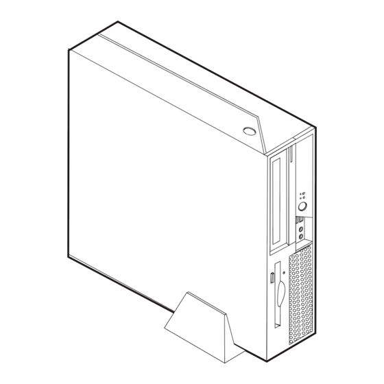
Page 10: Locating Controls And Connectors On The Front Of Your Computer
Locating controls and connectors on the front of your computer The following illustration shows locations of the controls and connectors on the front of your computer. Note: Not all computer models will have the following controls and connections. Optical drive or second hard disk USB connectors (2) drive (some models) Hard disk drive activity indicator... -
Page 11: Locating Connectors On The Rear Of Your Computer
Locating connectors on the rear of your computer The following illustration shows locations of connectors on the rear of your computer. Power cord connector Parallel connector Cable lock (Kensington) latch Audio line-in connector PCI Express (x1) adapter Audio line-out connector connector PCI adapter connector USB connectors (2) -
Page 12: Identifying Parts On The System Board
Identifying parts on the system board The following illustration shows the locations of parts on the system board. Memory connector 1 Diskette drive connector Memory connector 2 Front panel connector SATA IDE connectors (2) Power supply connector PCI riser connector PATA primary IDE connector Battery 12V power connector... -
Page 13: Chapter 2. Replacing Hardware
4. Remove the floor stand, if attached. 5. Remove any locking devices, such as a cable lock, that secure the computer cover. 6. Press inward on the two buttons and pivot the top cover upward. © Lenovo 2005. Portions © IBM Corp. 2005. -
Page 14: Replacing The Power Supply
Hardware Maintenance Manual (HMM) for the computer. To obtain copies of the Quick Reference or the HMM, go to the Support Web site at http://www.lenovo.com/think/support. To replace the power supply: 1. Remove the screws at the rear of the chassis that secure the power supply. - Page 15 9. Install the new power supply into the chassis so that the screw holes in the power supply assembly align with those in the chassis. Note: Use only the screws provided by Lenovo. 10. Install and tighten the assembly screws into the rear of the chassis.
-
Page 16: Replacing The System Board Assembly
Hardware Maintenance Manual (HMM) for the computer. To obtain copies of the Quick Reference or the HMM, go to the Support Web site at http://www.lenovo.com/think/support. To replace the system board assembly: 1. Turn off the computer and allow the computer to cool for one hour. - Page 17 4. While holding the rear of the computer chassis down, pull upward on the handle provided to remove the PCI riser assembly and any adapters that are currently installed. 5. Disconnect the cables connected to the system board. See “Identifying parts on the system board”...
- Page 18 Note: You will have to tilt the system board assembly and move it around the edge of the power supply assembly to remove it from the computer. 7. Place the defective system board next to the new system board on a clean, flat surface.
- Page 19 11. Use the vacuum pen 1 to lift the microprocessor straight up and out of the socket. Important Do not touch the gold contacts on the bottom of the microprocessor. Use the vacuum pen provided to remove and install the microprocessor. If you must touch the microprocessor, touch only the sides.
-
Page 20: Replacing The Microprocessor
Quick Reference that was included with your computer or in the Hardware Maintenance Manual (HMM) for the computer. To obtain copies of the Quick Reference or the HMM, go to the Support Web site at http://www.lenovo.com/think/support. This section provides instructions on how to replace the microprocessor. Important... - Page 21 Important When you receive a new microprocessor, you will also receive a new heat sink and vacuum pen. You must use the new heat sink with the new microprocessor. If you use the old heat sink with the new microprocessor, your computer might overheat causing intermittent problems.
- Page 22 3. Release the lever 1 holding the microprocessor heat sink. 4. Remove the heat sink from the system board. Important Do not use the old heat sink with the a new microprocessor. If you use the old heat sink with the new microprocessor, your computer might overheat causing intermittent problems.
- Page 23 6. Use the vacuum pen 1 to lift the microprocessor straight up and out of the socket. Important Do not touch the gold contacts on the bottom of the microprocessor. If you must touch the microprocessor, touch only the sides. a.
- Page 24 8. Loosen the black cover 3 that protect the gold contacts on the new microprocessor 2 , but do not remove the black cover. Use the vacuum pen 1 to pick up the microprocessor, and then completely remove the black cover.
-
Page 25: Replacing A Memory Module
Hardware Maintenance Manual (HMM) for the computer. To obtain copies of the Quick Reference or the HMM, go to the Support Web site at http://www.lenovo.com/think/support. To replace the memory modules: 1. Open the computer cover. See “Opening the cover” on page 5. - Page 26 2. While holding the rear of the computer chassis down, pull upward on the handle provided to remove the PCI riser assembly and any adapters that are currently installed. 3. Pivot the drive bay assembly upward to gain access to the memory module. Hardware Replacement Guide...
- Page 27 4. Locate the memory connectors. See “Identifying parts on the system board” on page 4. 5. Remove the memory module being replaced by opening the retaining clips as shown. 6. Position the replacement memory module over the memory connector. Make sure the notch 1 on the memory module aligns correctly with the connector key 2 on the system board.
-
Page 28: Replacing An Adapter
Hardware Maintenance Manual (HMM) for the computer. To obtain copies of the Quick Reference or the HMM, go to the Support Web site at http://www.lenovo.com/think/support. To replace the adapter: 1. Open the computer cover. See “Opening the cover” on page 5. - Page 29 3. Pivot the adapter latch to release the adapter. 4. Remove the adapter being replaced from the PCI riser. 5. Remove the new adapter from its static-protective package. 6. Install the new adapter into the appropriate connector into the PCI riser. 7.
-
Page 30: Replacing A Hard Disk Drive
Hardware Maintenance Manual (HMM) for the computer. To obtain copies of the Quick Reference or the HMM, go to the Support Web site at http://www.lenovo.com/think/support. Important When you receive a new hard disk drive, you also receive a set of Product Recovery CDs. - Page 31 4. Disconnect the signal and power cables from the rear of the hard disk drive. 5. Pivot the hard disk drive and bracket to the rear, then pull the hard disk drive out of the hard drive bay by pulling on the blue handle. 6.
-
Page 32: Replacing An Optical Drive
Hardware Maintenance Manual (HMM) for the computer. To obtain copies of the Quick Reference or the HMM, go to the Support Web site at http://www.lenovo.com/think/support. To replace the optical drive: 1. Open the computer cover. See “Opening the cover” on page 5. - Page 33 2. Pivot the drive bay assembly upward to gain access to the cable connections. 3. Disconnect the signal and power cables from the rear of the optical drive. 4. Slide the optical drive lock 1 to the unlocked position. 5. Open the door at the front of the optical drive and slide it out the front of the computer.
-
Page 34: Replacing The Diskette Drive
Hardware Maintenance Manual (HMM) for the computer. To obtain copies of the Quick Reference or the HMM, go to the Support Web site at http://www.lenovo.com/think/support. To replace the diskette drive: 1. Open the computer cover. See “Opening the cover” on page 5. -
Page 35: Replacing The Fan Assembly
Hardware Maintenance Manual (HMM) for the computer. To obtain copies of the Quick Reference or the HMM, go to the Support Web site at http://www.lenovo.com/think/support. To replace the fan assembly: 1. Open the computer cover. See “Opening the cover” on page 5. - Page 36 4. Remove the front bezel by releasing the tab as shown. 5. Remove the plastic insert behind the bezel by releasing the tabs as shown. Hardware Replacement Guide...
- Page 37 6. Release the tabs as shown holding the fan assembly. 7. Remove the fan assembly. 8. Install the new fan assembly and connect the fan cable to the system board. 9. Reinstall the plastic insert. 10. Reinstall the front bezel. 11.
-
Page 38: Replacing The Keyboard
Hardware Maintenance Manual (HMM) for the computer. To obtain copies of the Quick Reference or the HMM, go to the Support Web site at http://www.lenovo.com/think/support. To replace the keyboard: 1. Remove any media (diskettes, CDs, or tapes) from the drives, shut down your operating system, and turn off all attached devices and the computer. -
Page 39: Replacing The Internal Speaker
Hardware Maintenance Manual (HMM) for the computer. To obtain copies of the Quick Reference or the HMM, go to the Support Web site at http://www.lenovo.com/think/support. To replace the internal speaker: 1. Open the computer cover. See “Opening the cover” on page 5. -
Page 40: Completing The Cru Replacement
3. Locate the speaker 1 See “Locating components” on page 1. 4. Disconnect the speaker cable from the system board. See “Identifying parts on the system board” on page 4. Note: Make sure you note the location of the speaker cable when you disconnect it from the system board. -
Page 41: Updating (Flashing) Bios From A Diskette Or Cd-Rom
9. To update your configuration, see ″Starting the Setup Utility″ in the Quick Reference. Note: In most areas of the world, Lenovo requires the return of the defective CRU. Information about this will come with the CRU or will come a few days after the CRU arrives. - Page 42 4. When prompted to change the serial number, press Y. 5. Type in the seven character serial number of your computer and then press Enter. 6. When prompted to change the machine type/model, press Y. 7. Type in the seven character machine type/model of your computer and then press Enter.
-
Page 43: Appendix. Notices
Web sites. The materials at those Web sites are not part of the materials for this Lenovo product, and use of those Web sites is at your own risk. -
Page 44: Television Output Notice
Macrovision Corporation. Reverse engineering or disassembly is prohibited. Trademarks The following terms are trademarks of Lenovo in the United States, other countries, or both: Lenovo ThinkCentre IBM is a trademarks of International Business Machines Corporation in the United States, other countries, or both. - Page 46 Part Number: 41D4499 Printed in USA (1P) P/N: 41D4499...