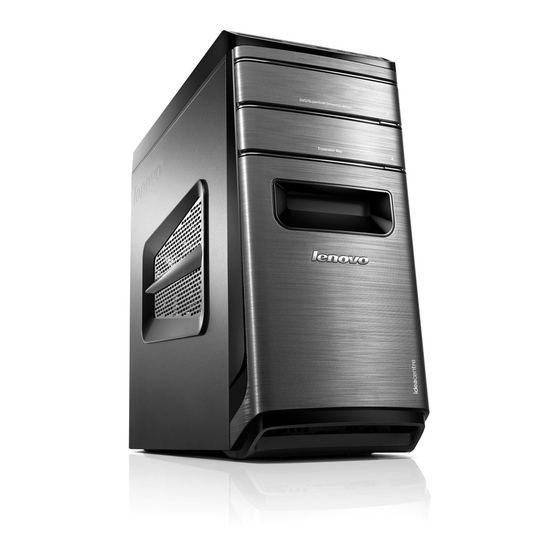
Lenovo IdeaCentre K410 Hardware Maintenance Manual
Hide thumbs
Also See for IdeaCentre K410:
- User manual (69 pages) ,
- Hardware maintenance manual (57 pages) ,
- Manual (43 pages)

Related Manuals for Lenovo IdeaCentre K410


Summary of Contents for Lenovo IdeaCentre K410
- Page 1 IdeaCentre K430/K410 Hardware Maintenance Manual Machine Types: 10086/3109/4743 K430; 10089/1168/4744 K410...
- Page 3 IdeaCentre K430/K410 Hardware Maintenance Manual Machine Types: 10086/3109/4743 K430; 10089/1168/4744 K410...
-
Page 5: Table Of Contents
..Selecting a startup device ..Exiting the Lenovo BIOS Setup Utility program . . Chapter 6. Symptom-to-FRU Index . . 19 Hard disk drive boot error .. - Page 6 IdeaCentre K430/K410Hardware Maintenance Manual...
-
Page 7: Chapter 1. About This Manual
This manual contains service and reference information for IdeaCentre K430 & K410 computers listed on the cover. It is intended only for trained servicers who are familiar with Lenovo computer products. Before servicing a Lenovo product, be sure to read the Safety Information. - Page 8 IdeaCentre K430/K410Hardware Maintenance Manual...
-
Page 9: Chapter 2. Safety Information
Electrical current from power, telephone, and communication cables can be hazardous. To avoid personal injury or equipment damage, disconnect the attached power cords, telecommunication systems, networks, and modems before you open the computer covers, unless instructed otherwise in the installation and configuration procedures. © Copyright Lenovo 2012... - Page 10 Observe the following rules when working on electrical equipment. Important: Use only approved tools and test equipment. Some hand tools have handles covered with a soft material that does not insulate you when working with live electrical currents. Many customers have, near their equipment, rubber floor mats that contain small conductive fibers to decrease electrostatic discharges.
-
Page 11: Safety Inspection Guide
– Send another person to get medical aid. Safety inspection guide The intent of this inspection guide is to assist you in identifying potentially unsafe conditions on these products. Each machine, as it was designed and built, had required safety items installed to protect users and service personnel from injury. -
Page 12: Grounding Requirements
• Avoid contact with other people while handling the part. • Wear a grounded wrist strap against your skin to eliminate static on your body. • Prevent the part from touching your clothing. Most clothing is insulative and retains a charge even when you are wearing a wrist strap. - Page 13 To Connect 1. Turn everything OFF. 2. First, attach all cables to devices. 3. Attach signal cables to connectors. 4. Attach power cords to outlet. 5. Turn device ON. CAUTION: When replacing the lithium battery, use only Part Number 45C1566 or an equivalent type battery recommended by the manufacturer.
- Page 14 ≥18 kg(37 lbs) ≥32 kg(70.5 lbs) ≥55 kg(121.2 lbs) CAUTION: Use safe practices when lifting. CAUTION: The power control button on the device and the power switch on the power supply do not turn off the electrical current supplied to the device. The device also might have more than one power cord.
-
Page 15: Chapter 3. General Information
This section lists the physical specifications. Environment Air temperature: Operating: 10° to 35°C Transit: -20° to 55°C Humidity: Operating: 35% to 80% Transit: 20% to 90% (40°C) Altitude: 86KPa to 106KPa Electrical input: Input voltage: 90V-264V(AC) Input frequency: 47Hz-63Hz © Copyright Lenovo 2012... - Page 16 IdeaCentre K430/K410Hardware Maintenance Manual...
-
Page 17: Chapter 4. General Checkout
• If the computer displays a POST error, go to “POST error codes”. • If the computer hangs and no error is displayed, continue at step 7. 7. If the test stops and you cannot continue, replace the last device tested. © Copyright Lenovo 2012... - Page 18 IdeaCentre K430/K410Hardware Maintenance Manual...
-
Page 19: Chapter 5. Using The Setup Utility
1. If your computer is already on when you start this procedure, shut down the operating system and turn off the computer. 2. Press and hold the F1 key then turn on the computer. When the Lenovo BIOS Setup Utility program is displayed, release the F1 key. - Page 20 5. Select Save changes and Exit from the menu. Power-On Password When a Power-On Password is set, you cannot start the Lenovo BIOS Setup Utility program until a valid password is typed from the keyboard. Setting, changing, or deleting a Power-On Password Note: A password can be any combination of letters and numbers up to 16 character (a-z, and 0-9).
-
Page 21: Enabling Or Disabling A Device
To set a Power-On Password, do the following: 1. Start the Lenovo BIOS Setup Utility program (See ”Starting the Lenovo BIOS Setup Utility program” on page 13.) 2. From the Security menu, select Set Power-On Password and press the Enter key. -
Page 22: Selecting A Startup Device
Selecting or changing the startup device sequence To view or permanently change the configured startup device sequence, do the following: 1. Start the Lenovo BIOS Setup Utility program (see “Starting the Lenovo BIOS Setup Utility program” on page 13). 2. From the Lenovo BIOS Setup Utility program main menu, select the Startup option. -
Page 23: Exiting The Lenovo Bios Setup Utility Program
Exiting the Lenovo BIOS Setup Utility program After you finish viewing or changing settings, press the Esc key to return to the Lenovo BIOS Setup Utility program main menu. You might have to press the Esc key several times. Do one of the following: •... - Page 24 IdeaCentre K430/K410Hardware Maintenance Manual...
-
Page 25: Chapter 6. Symptom-To-Fru Index
• System Board Power Supply connectors • Microprocessor(s) connection Check the power cord. Check the power-on switch. © Copyright Lenovo 2012 FRU/Action Check the configuration and ensure the startup drive is in the boot sequence. Install an operating system on the boot drive. -
Page 26: Post Error Codes
POST error codes Each time you turn the computer on, it performs a series of tests to check that the system is operating correctly and that certain options are set. This series of tests is called the Power-On Self-Test, or POST. POST does the following: •... -
Page 27: Chapter 7. Locations
It provides basic computer functions and supports a variety of devices that are factory-installed or that you can install later. The following illustrations show the locations of the different parts on the system board. © Copyright Lenovo 2012 Memory modules System fan... - Page 28 12V power connector Microprocessor and heat sink Microprocessor fan connector Memory slots (4) Power connector Mini PCI Express slot PCI Express × 16 adapter slots (2) Power fan header Front panel connector IdeaCentre K430/K410Hardware Maintenance Manual IdeaCentre K430 Front USB connector Front USB connector Mode SW connector Serial (COM2)connector...
-
Page 29: Product View
12V power connector Microprocessor and heat sink Microprocessor fan connector Memory slots (2) Thermal sensor header connector Power connector Battery SATA connectors (3) eSATA connector IdeaCentre K410 Power fan header Front panel connector Clear CMOS jumper Front USB connectors (2) Mini PCI Express slot PCI Express ×... - Page 30 IdeaCentre K430/K410Hardware Maintenance Manual...
-
Page 31: Chapter 8. Replacing Hardware
Before proceeding with the disassembly procedure, make sure that you do the following: 1. Turn off the power to the system and all peripherals. 2. Unplug all power and signal cables from the computer. 3. Place the system on a flat, stable surface. © Copyright Lenovo 2012... -
Page 32: Replacing The Keyboard And Mouse
Replacing the keyboard and mouse Note: Your keyboard will be connected to a USB connector at either front or at the rear of the computer. To replace the keyboard: Step 1. Remove any media (disks, CDs, or memory cards) from the drives, shut down the computer, and turn off all attached devices. -
Page 33: Removing The Front Bezel
Step 5. Slide the computer cover out to remove it. Step 6. To reinstall the computer cover: Line up the computer cover with the chassis then slide it back. Secure the computer cover to the chassis with the screws. Removing the front bezel Note: For this procedure, it helps to lay the computer flat. -
Page 34: Replacing A Memory Module
Step 2. Remove the front bezel by releasing the three plastic tabs inside the chassis and sliding the bezel out as shown. Step 3. To reattach the bezel, align the plastic tabs on the bottom of the bezel with the corresponding holes in the chassis, and then snap it into position. -
Page 35: Replacing A Hard Disk Drive
Step 4. Position the new memory module over the memory connector. Make sure that the notch memory module aligns correctly with the connector key module straight down into the connector until the retaining clips close. Step 5. Reattach the computer cover. Replacing a hard disk drive Note: For this procedure, it helps to lay the computer flat. -
Page 36: Replacing An Optical Drive
Step 4. Remove the hard disk drive from the plastic bracket as shown. Step 5. Line up the new hard disk drive with the plastic bracket and snap it into position. Step 6. Slide the new hard disk drive into the drive bay and slide the drive bay into place. Step 7. -
Page 37: Replacing A Graphics Card
Replacing a graphics card Note: For this procedure, it helps to lay the computer flat. To replace a graphics card: Step 1. Remove the computer cover. Refer to “Removing the computer cover”. Step 2. Follow the below steps to remove a graphics card: If your computer has a Duo-graphics cards installed, follow the steps below to replace it: Remove the screw that secures the Duo-graphics cards fixing bracket and lift the bracket up. - Page 38 Remove the screw that secures the graphics card latch to the chassis, open it, and remove the Duo-graphics cards connector. Remove the graphics card by pulling it straight out of the connector. If your computer has a single graphics card installed, follow the steps below to replace it: IdeaCentre K430/K410Hardware Maintenance Manual...
-
Page 39: Replacing The Tv-Tuner Card
Remove the screw that secures the graphics latch to the chassis and open it. Remove the graphics card by pulling it straight out of the connector. Step 3. Install the new adapter into the same adapter connector. Step 4. Turn the graphics card latch to the closed position and secure it with the screw. Step 5. - Page 40 To replace the TV-Tuner card: Step 1. Remove the computer cover. Refer to “Removing the computer cover”. Step 2. Remove the screw that secures the graphics card latch to the chassis and open it. Step 3. Remove the TV-Tuner card by pulling it straight out of the connector. Step 4.
-
Page 41: Replacing The Power Supply
Step 6. Reattach the computer cover. Replacing the Power supply Note: For this procedure, it helps to lay the computer flat. To replace the Power supply: Step 1. Remove any media (disks, CDs, DVDs, or memory cards) from the drives, shut down the operating system, and turn off the computer and all attached devices. -
Page 42: Replacing Microprocessor Fan
Step 1. Remove any media (disks, CDs, DVDs, or memory cards) from the drives, shut down the operating system, and turn off the computer and all attached devices. Step 2. Unplug all power cords from electrical outlets. Step 3. Disconnect all cables attached to the computer. This includes power cords, input/output (I/O) cables, and any other cables that are connected to the computer. -
Page 43: Replacing The Cpu
Step 3. Disconnect all cables attached to the computer. This includes power cords, input/output (I/O) cables, and any other cables that are connected to the computer. Refer to “Left and right view” and “Rear view” for help with locating the various connectors. Step 4. - Page 44 Step 4. Remove the computer cover. Refer to “Removing the computer cover”. Step 5. Remove the microprocessor fan. Refer to “Replacing the microprocessor fan”. Step 6. Remove the heat-sink. Refer to “Replacing the heat-sink”. Step 7. To remove the microprocessor to spring it up.
-
Page 45: Replacing The Wi-Fi Card
Step 8. Holding the sides of the microprocessor with your fingers, remove the protective cover protects the gold contacts on the new microprocessor. Step 9. Holding the sides of the microprocessor with your fingers, position the microprocessor so that the notches on the microprocessor are aligned with the tabs in the microprocessor socket. -
Page 46: Replacing The Motherboard
To replace the Wi-Fi card: Step 1. Remove any media (disks, CDs, DVDs, or memory cards) from the drives, shut down the operating system, and turn off the computer and all attached devices. Step 2. Unplug all power cords from electrical outlets. Step 3. -
Page 47: Fru Lists
Step 2. Unplug all power cords from electrical outlets. Step 3. Disconnect all cables attached to the computer. This includes power cords, input/output (I/O) cables, and any other cables that are connected to the computer. Refer to “Left and right view” and “Rear view”... -
Page 48: Fru Lists
Mic_S D9PFW 2GB DDRIII1333 RAM(R) Elp_R J2108BCSE-DJ-F 2GB DDRIII1333 RAM® Psc_S A3P2GF3CKF-GDJ 2GB D3-1333 RAM M378B5773DH0-CH900 2GB DDRIII1333 RAM® Mic_S D9LGK 2GB DDRIII1333 RAM(R) HMT325U6BFR8C-H9 2GB DDRIII1333 RAM® IdeaCentre K430/K410Hardware Maintenance Manual Lenovo P/N 1100334 1100335 1100336 1100337 1100338 1100456... - Page 49 MT8JTF25664AZ-1G4D1 2GB DDRIII1333 RAM(R) HMT351U6CFR8C-H9 4GB D3-1333 RAM-HF MT16KTF51264AZ-1G4M1 4GB D3-1333 RAM-HF EBJ41UF8BDW0-GN-F 4GB D3-1600 RAM-HF Mic_R D9PFW 4GB DDRIII1333 RAM(R) Mic_S D9PFW 4GB DDRIII1333 RAM(R) Psc_S A3P2GF3CKF-GDJ 4GB D3-1333 RAM(R) Elp_R J2108BCSE-DJ-F 4GB DDRIII1333 RAM® M378B5273DH0-CH900 4GB DDRIII1333 RAM® MT16JTF51264AZ-1G4D1 4GB DDRIII1333 RAM(R) HMT351U6BFR8C-H9N0 4GB DDRIII1333 RAM(R) HMT325U6CFR8C-H9 2GB D3-1333 RAM-HF...
- Page 50 Seagate Grenada ST2000DM001 2TB HDDLH Samsung PM830 64G mSATA SSD Samsung PM830 128G mSATA SSD Portable Hard Disk Drive Lenovo Portable HardDrive(SP) F410(500G) Optical Drive PLDS 16XDH16ABSH SATA Black DVDRWLH TSST 16XSH216AB SATA Black DVDRWLH HLDS 16XGH70N SATA Black DVDRWLH...
- Page 51 Bitland @Geforce GT 630@2G/A/DB/H Graphic Card Power Supply HuntKey HK380-12GP S2(S7) ATX280W Power Supply LiteonPS-5281-7VR5-RoHS ATX280W Power Supply AcBelPC6001-EL9G ATX280W Power Supply FSP280-50EPA ATX280W 85% Power Supply LiteonPS-5281-02VA-RoHS ATX280W 85% Power Supply AcBelPC9008-EL1G ATX280W 85% Power Supply AcBel PC7033-EL0G 450W NEW CABLE Power Supply(R) AcBel PC6001EL6G ATX 280W Robust Power Supply(R) HuntKey HK38012GP S2 ATX 280W WW Power Supply(R) Liteon PS52817VR4ROHS ATX280W TW cap Power Supply...
- Page 52 Luxshare 2H100mm HDD Power Supply adaptor with Latch(R) MSI graphics card SLI cable ATI graphics card crossfire cable JT Z75 MB rearIO shielding Monitor Lenovo Black LI2361dwA/TPV/A/R/WW Lenovo Black LI2361dwA/TPV/A/R/CN Lenovo L2262wA/TPV/A/R/WW 0560HB1 Lenovo Black L2262wA/TPV/A/R/CN Lenovo L2262w/TPV/A/R/WW/W3Y/S/D Lenovo Black L2062wA/TPV/A/R/WW...
- Page 53 Mechanical JT LX319 K4 chassis card bracket JT mobile HDD case RoatonK4 Bitland mSATA Conversion Card JT SSD plastic bracket JT M2X3 Dedicated Screw Chassis JT LX-319CTA Front Bezel JT LX-319CTA Upper Bezel with Mode Switch & Power Botton JT LX-319CTA ODD holder JT Tinian LX-320AT hard drive rail AVC DS09225R12HP183 9225 Sysfan(R) FOX PV902512PSPF 0J-G-2 9225 Sysfan(R)
- Page 54 Sunrex LXH-EKB-10YA(SP) B-Silk KB-LVT Sunrex LXH-EKB-10YA(SL) B-Silk KB-LVT Sunrex LXH-EKB-10YA(NL) B-Silk KB-LVT Sunrex LXH-EKB-10YA(IT) B-Silk KB-LVT Sunrex LXH-EKB-10YA(HB) B-Silk KB-LVT Sunrex LXH-EKB-10YA(FR) B-Silk KB-LVT Sunrex LXH-EKB-10YA(BE) B-Silk KB-LVT Sunrex LXH-EKB-10YA(GK) B-Silk KB-LVT Sunrex LXH-EKB-10YA(HG) B-Silk KB-LVT Sunrex LXH-EKB-10YA(BG) B-Silk KB-LVT Sunrex LXH-EKB-10YA(HR) B-Silk KB-LVT Sunrex LXH-EKB-10YA(BR) B-Silk KB-LVT Sunrex LXH-EKB-10YA(JP) B-Silk KB-LVT...
- Page 55 Liteon SK-8861(IL) S-Silk KB-Black(WW) Liteon SK-8861(FR) S-Silk KB-Black(WW) Liteon SK-8861(BE) S-Silk KB-Black(WW) Liteon SK-8861(GR) S-Silk KB-Black(WW) Liteon SK-8861(HU) S-Silk KB-Black(WW) Liteon SK-8861(BG) S-Silk KB-Black(WW) Liteon SK-8861(KR) S-Silk KB-Black(WW) Liteon SK-8861(BR) S-Silk KB-Black(WW) Liteon SK-8861(JP) S-Silk KB-Black(WW) Liteon SK-8861(EN-FR)S-Silk KB-Black(WW) Liteon SM-8861(WW) Mouse Black Liteon SM-8861 Mouse(No Battery) Black Liteon SM-8861(JP) Mouse-Black(WW) 90200714...
- Page 56 IdeaCentre K430/K410Hardware Maintenance Manual...
-
Page 57: Chapter 9. General Information
• Wake Up on Alarm: You can specify a date and time at which the computer will be turned on automatically. This can be either a single event , a daily event or a weekly event. • Wake Up on LAN: This feature allows LAN adapter card to wake the System. © Copyright Lenovo 2012...