Table of Contents
Advertisement
Quick Links
SERVICE MANUAL
Ver 1.0 2000. 12
SPECIFICATIONS
Frequency range:
FM: 87.5 – 108 MHz
SW: 4.75 – 18.0 MHz
MW: 530 – 1 605 kHz
Speaker
Approx. 9.2 cm (3
Output
v jack (ø 3.5 mm minijack)
Power output
350 mW (at 10 % harmonic distortion)
Power requirements
3 V DC, two R20 (size D) batteries
Dimensions
Approx. 233 × 119.2 × 56 mm (w/h/d)
× 4
× 2
1
3
(9
/
/
4
4
and controls
Mass
Approx. 815 g (29 oz) incl. batteries
Supplied accessories
(Middle Eastern model only)
Case (1)
Hand strap (1)
Design and specifications are subject to change
without notice.
inches) dia., 8 Ω
5
/
8
1
/
in.) incl. projecting parts
4
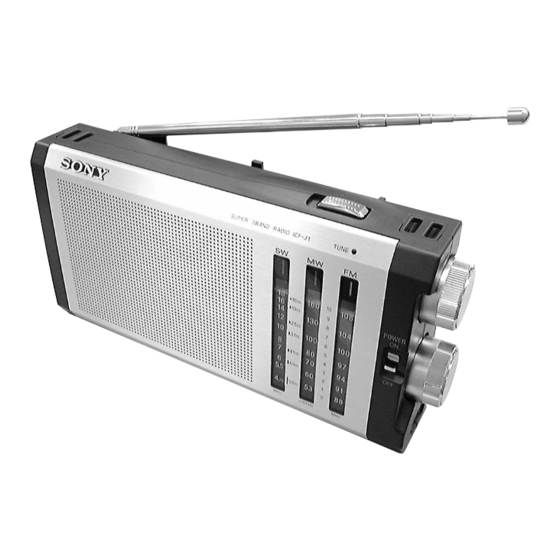
ICF-J1
Battery life (approx. hours)
When using
FM
Sony alkaline
240
LR20 (size D) batteries
Sony
120
R20 (size D) batteries
Features
• High power sound
• Long battery life with two R20 (size D)
batteries
• High sensitivity
• Easy tuning with the tuning indicator
FM/SW/MW 3 BAND RADIO
E Model
SW/MW
250
130
Advertisement
Table of Contents

Related Manuals for Sony ICF-J1


Summary of Contents for Sony ICF-J1
- Page 1 ICF-J1 SERVICE MANUAL E Model Ver 1.0 2000. 12 SPECIFICATIONS Battery life (approx. hours) Frequency range: FM: 87.5 – 108 MHz When using SW/MW SW: 4.75 – 18.0 MHz MW: 530 – 1 605 kHz Sony alkaline LR20 (size D) batteries Speaker inches) dia., 8 Ω...
-
Page 2: Table Of Contents
SECTION 1 GENERAL TABLE OF CONTENTS This section is extracted from instruction manual. GENERAL ..............2 DISASSEMBLY ............3 Telescopic antenna Antena telescópica ASSEMBLY ..............7 ELECTRICAL ADJUSTMENTS ......9 DIAGRAMS 5-1. Block Diagram ..............11 5-2. Printed Wiring Board ............13 5-3. -
Page 3: Disassembly
SECTION 2 DISASSEMBLY • This set can be disassemble in the order shown below. Lid, Battery Case “Antenna, Telescopic (FM/SW) (ANT1)”, “Cabinet (Rear)” “Knob (Tuning)”, “Knob (Volume)” Chassis Section Main Board Chassis Antenna, Ferrite-Red (MW) (L1) Speaker (9.2 cm) (SP1) Note: Follow the disassembly procedure in the numerical order given. - Page 4 “ANTENNA, TELESCOPIC (FM/SW) (ANT1)”, “CABINET (REAR)” Note: Arrange the antenna, wire to the 4 slots. 6 antenna, telescopic (FM/SW) (ANT1) 2 claw 5 lug, 3 4 screw (P2.6 × 8) antenna, wire 1 five screws (BTP3 × 12) 2 claw 7 cabinet (rear) CHASSIS SECTION Note: When mounting the battery terminals (+) and (–), engage the lead wires...
- Page 5 MAIN BOARD Note: For the mounting position 1 Remove three solders of the antenna, ferrite-rod (MW) (L1), of ferrite-rod (MW) refer to the “ANTENNA, antenna (L1) leads. 3 holder (gear) 4 screw FERRITE-ROD (MW) (L1)” (B2.6 × 5) in DISASSEMBLY. 2 screw 2 screw (BTP3 ×...
- Page 6 SPEAKER (9.2 cm) (SP1) 3 Remove speaker (SP1) in the direction of arrow A . speaker (9.2 cm) (SP1) speaker lead wire (RED) claw cabinet (front) speaker lead wire (WHT) 2 claw 1 Remove shaded portion bond SC-108. Note: When installing the speaker (SP1), set it in the position as shown, and apply the bond SC-108 to the removed portion.
-
Page 7: Assembly
SECTION 3 ASSEMBLY Note: Follow the assembly procedure in the numerical order given. DIAL POINTER SETTING • RACK boss 6 gear, midway 1 rack 5 shaft, tuning 2 Meet the portion of the rack with the mark of the chassis. boss chassis mark... - Page 8 • “GEAR (TUNING CAPACITOR)”, “SPRING (GEAR)” AND “GEAR (B), TUNING CAPACITOR” 1 Turn variable condenser (CV1) shaft fully to the arrow direction Note: Make sure that two tuning capacitor gears (ant1-clok wise). are meshing with the midway gear. gear, midway gear, midway 2 gear (tuning capacitor) Including “spring (gear)”,...
-
Page 9: Electrical Adjustments
SECTION 4 ELECTRICAL ADJUSTMENTS 0 dB=1 µV AM IF ADJUSTMENT Adjust for a maximum reading on level meter [MW] 455 kHz Setting: Band switch : MW MW FREQUENCY COVERAGE ADJUSTMENT Put the lead-wire Adjust for a maximum reading on level meter AM RF signal TP8 (SP +) antenna close to... - Page 10 Adjustment Location: SW Frequency Coverage Adjustment – MAIN BOARD (Component Side) – SW Tracking MW Frequency Adjustment Coverage Adjustment CT1-4 CT1-1 MW Tracking Adjustment CT1-2 FM Tracking Adjustment CT1-3 FM Frequency Coverage Adjustment AM IF Adjustment – MAIN BOARD (Conductor Side) – TP1 (ANT IN) TP2 (GND) TP9 (SP –)
-
Page 11: Diagrams
ICF-J1 SECTION 5 DIAGRAMS 5-1. BLOCK DIAGRAM ANT1 CT1 – 2 CV1 – 3 FM/SW FM RF FM OSC TELESCOPIC CV1 – 2 CT1 – 3 ANTENNA CT1 – 2, L3 CT1 – 3, L4 FM TRACKING FM FREQUENCY COVERAGE... -
Page 12: Printed Wiring Board
ICF-J1 5-2. PRINTED WIRING BOARD • Semiconductor Location Ref. No. Location MAIN BOARD TUNE MW FERRITE-ROD ANTENNA SW OSC NATURAL – 6 – 4 – 2 BAND ANT1 – 5 – 3 – 1 FM/SW TELESCOPIC ANTENNA TP1 (ANT IN) -
Page 13: Schematic Diagram
ICF-J1 5-3. SCHEMATIC DIAGRAM • IC Block Diagrams IC1 CXA1019S 29 28 27 26 18 17 16 AM IF DET AGC TUNING METER AF POWER AMP AM FE FM IF DISCRIMINATOR FM FE IC2 BA6640F-E2 18 17 15 14 11 10 RIPPLE FILTER –... -
Page 14: Exploded Views
SECTION 6 EXPLODED VIEWS NOTE: • -XX and -X mean standardized parts, so they • Items marked “*” are not stocked since they may have some difference from the original are seldom required for routine service. Some one. delay should be anticipated when ordering •... - Page 15 (2) CHASSIS SECTION Ref. No. Part No. Description Remark Ref. No. Part No. Description Remark 3-223-764-01 KNOB (POWER) 3-369-208-01 GEAR (B), TUNING CAPACITOR 3-223-767-01 POINTER 3-364-941-11 SCREW (+B) (2.6X5), NYLOK 3-223-772-01 PLATE, BACK 3-223-759-01 HOLDER (GEAR) 3-223-766-01 RACK * 63 A-3683-250-A MAIN BOARD, COMPLETE * 55 3-223-758-01 CHASSIS...
-
Page 16: Electrical Parts List
SECTION 7 MAIN ELECTRICAL PARTS LIST NOTE: • Items marked “*” are not stocked since they • Due to standardization, replacements in the When indicating parts by reference number, please include the board. parts list may be different from the parts speci- are seldom required for routine service. - Page 17 ICF-J1 MAIN Ref. No. Part No. Description Remark Ref. No. Part No. Description Remark 1-410-294-11 INDUCTOR 38uH < TRANSISTOR > 8-729-120-28 TRANSISTOR 2SC1623-L5L6 8-729-904-87 TRANSISTOR 2SB1197K-R < RESISTOR > 1-216-825-11 METAL CHIP 2.2K 1/16W 1-216-815-11 METAL CHIP 1/16W 1-216-833-11 METAL CHIP...