
Related Manuals for Panasonic LonWorks CZ-CLNC2


Summary of Contents for Panasonic LonWorks CZ-CLNC2
-
Page 1: Table Of Contents
LonWorks Interface (CZ-CLNC2) INSTALLATION INSTRUCTIONS Contents --- LonWorks Interface Overview Product Overview System Diagram Functions Procedures for Installation (Electrical Work) of LonWorks Interface Safety Precautions Included Parts Installation Method Wiring Specifications LonWorks Interface Structure Power Board Initial Settings Power Board Wiring Wiring Procedure Main Circuit Board Indoor Unit Enabling Switches... -
Page 2: Lonworks Interface Overview
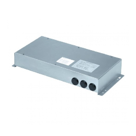
1. LonWorks Interface Overview Product Overview This interface is a communications interface for connecting LonWorks to an air conditioner unit control network. From the host connected to LonWorks, basic settings and status monitoring is possible for up to 16 groups of A/C units. System Diagram Outdoor Indoor Unit... -
Page 3: Functions
Functions Start/stop Temp. setting(*1) A/C unit settings Settings for Operation mode from the each group of LonWorks indoor units Option 1 settings(*2) Option 2 settings(*2) Settings for all units Emergency stop Start/stop Temp. setting Operation mode A/C unit status notifications made Option 1 settings(*2) to the LonWorks Option 2 settings(*2) -
Page 4: Procedures For Installation (Electrical Work) Of Lonworks Interface
2. Procedures for Installation (Electrical Work) of LonWorks Interface Installation Method Safety Precautions • The screws used to install the main unit must be provided by the * The following is intended for the installer responsible for installation and test operations of the LonWorks Interface, and installer. -
Page 5: Power Board Initial Settings
Wiring Procedure Power Board Initial Settings • Connect the power supply lines to the L and N power Not Install: Ordinarily, keep this set to “Not Install” (initial supply terminals. setting). (the power suplly neutral to the N terminal.) Install: Free topology terminal resistor (51Ω) for the •... -
Page 6: Indoor Unit Enabling Switches
Indoor Unit Enabling Switches Address Switches 1 2 3 4 5 6 OFF Indoor unit group 3 is disabled. 1 2 3 4 Indoor unit group 3 is enabled. O : ON - : OFF OFF Indoor unit group 2 is disabled. Indoor unit group 2 is enabled. -
Page 7: Communication Led (Green)
Communications LED (Green) • Display of A/C unit communications status Display meaning Indoor unit OFF: Waiting for initial communication group Low-speed flashing: Waiting for minimum COM: Communications transmission interval High-speed flashing: Initial communication in LD001 LD002 Display meaning progress ①Power OFF ON: Normal communications in progress ②... -
Page 8: Assigning Central Control Addresses
3. Assigning Central Control Addresses • Before assigning central control addresses for the LonWorks Interface, use the remote controller to make central control address settings for A/C units. • Follow only the steps for "Assigning Central Control Addresses" when a system controller or other central controller is already provided. -
Page 9: Lonworks Interface Test Run
4. LonWorks Interface Test Run Before performing a test run of the LonWorks Interface, perform test runs of the A/C units and assign central control addresses for A/C units. Indoor unit Gr STEP 5 Start/stop Start Data [LonWorks Interface Test Run Procedure] Start Start 3 4 5 6 7 8... -
Page 10: Checking The Lonworks Interface Version
5. Checking the LonWorks Interface Version • Version display (1) Press touch-switch S002. Version display mode is enabled on that circuit board for a 3 4 5 6 period of 18 seconds. LD001 illuminates, and LD002 flashes at high speed. 4 5 6 High-speed flashing 3 4 5... -
Page 11: List Of Lonworks Network Variables
6. List of LonWorks Network Variables A/C unit Input/output Item Variable name Variable type Start/stop nviOnOff_00 SNVT_switch Temp. setting nviSetPoint_00 SNVT_temp_p Operating mode nviHeatCool_00 SNVT_hvac_mode Input Option 1 setting nviOption1_00 SNVT_switch Option 2 setting nviOption2_00 SNVT_switch Start/stop status nvoOnOff_00 SNVT_switch Temp. -
Page 12: Details Of Lonworks Network Variables
7. Details of LonWorks Network Variables [nv1] Unit start/stop command [nv4] Temperature setting status notification network input SNVT_switch nviOnOff_00; network output SNVT_temp_p nvoSetpoint_01; network input SNVT_switch nviOnOff_01; network output SNVT_temp_p nvoSetpoint_01; network input SNVT_switch nviOnOff_02; network output SNVT_temp_p nvoSetpoint_02; network input SNVT_switch nviOnOff_03; network output SNVT_temp_p nvoSetpoint_03;... - Page 13 [nv7] Option 1 setting command [nv8] Option 1 setting status notification [nv9] Option 2 setting command [nv10] Option 2 setting status notification network input SNVT_switch nviOption1_00; network output SNVT_switch nvoOption1_00; network input SNVT_switch nviOption1_01; network output SNVT_switch nvoOption1_01; network input SNVT_switch nviOption1_02; network output SNVT_switch nvoOption1_02;...
- Page 14 [nv11] Alarm notification network output SNVT_switch nvoAlarm_00; Normal communications in progress (no alarms) network output SNVT_switch nvoAlarm_01; network output SNVT_switch nvoAlarm_02; 1~255 According to alarm code table network output SNVT_switch nvoAlarm_03; Indoor unit connected (initial communication in progress) These output network variables are output when an alarm occurs at an indoor unit, and when the alarm is reset at an indoor unit.
-
Page 15: Locations Where Neuron Id Is Applied
8. Locations Where Neuron ID is Applied The Neuron ID is applied in the following 3 locations. (1) Packaging box (2) Top panel lid (3) On the main circuit board Neuron chip Neuron ID Node0 : 00 03 18 69 95 01 Node1 : 00 03 18 69 96 01 Node2 : 00 03 18 69 97 01 Node3 : 00 03 18 69 98 01... - Page 16 ACXF60-29411 DC1018-0 Printed in Japan...