Table of Contents
Advertisement
Quick Links
M715q
User Guide and
Hardware Maintenance Manual
Machine Type (MT):
10M2, 10M3, 10M4, 10M5, 10RA, 10RB, 10RC, 10RD
Energy Star MT:
10M2, 10M3, 10M4, 10M5, 10RA, 10RB, 10RC, 10RD
Overview
Locations of indicators,
connectors, and
controls provided on
your computer.
Replaceable parts
Locations of the
replaceable parts on
your computer.
Locking the computer
Locking devices for
your computer.
Replacing customer
replaceable units
Replacing instructions
for customer
replaceable units.
Specifications
Specifications of your
computer.
Replacing field
replaceable units
Replacing instructions
for field replaceable
units (for technicians
only).
Advertisement
Table of Contents

Related Manuals for Lenovo 10M2


Summary of Contents for Lenovo 10M2
- Page 1 M715q User Guide and Hardware Maintenance Manual Machine Type (MT): 10M2, 10M3, 10M4, 10M5, 10RA, 10RB, 10RC, 10RD Energy Star MT: 10M2, 10M3, 10M4, 10M5, 10RA, 10RB, 10RC, 10RD Overview Locking the computer Specifications Locations of indicators, Locking devices for...
-
Page 2: Table Of Contents
Contents Overview .........3 Replacing the memory module .......32 Replacing the coin-cell battery .........33 Front view ............... 3 Replacing the Wi-Fi card ...........34 Rear view ................ 4 Replacing the wireless mouse .........37 System board ..............6 Replacing the wireless keyboard ......39 Machine type and model label ........ -
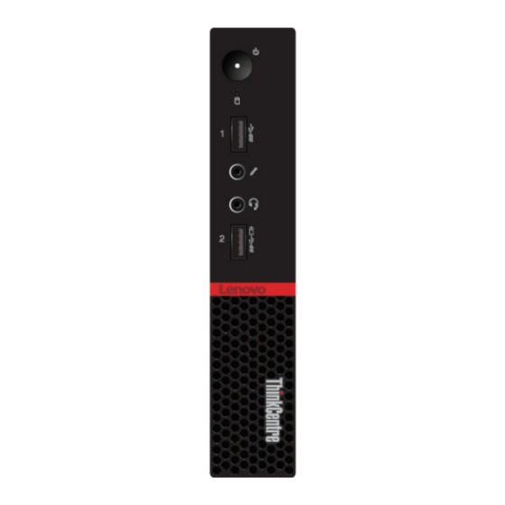
Page 3: Overview
Overview Front view Note Your computer model might look slightly different from the illustration. Power button Used to turn on your computer. You also can use the power button to turn off your computer when you cannot use the Microsoft® Windows® shutdown procedure normally to turn off your computer. -
Page 4: Rear View
Rear view Note Your computer model might look slightly different from the illustration. Wi-Fi antenna slot Used to install the rear Wi-Fi antenna cable connector that is optional. The rear Wi-Fi antenna is installed on the rear Wi-Fi antenna cable connector. Padlock loop Used to secure a padlock. - Page 5 USB 2.0 connector Used to connect a device, such as a keyboard, mouse, scanner, printer, or PDA, that requires a USB 2.0 connection. This USB 2.0 connector supports the smart power on feature that enables you to turn on the computer or wake it up from S4 hibernation mode by pressing Alt+P on the keyboard.
-
Page 6: System Board
System board Note Front view Rear view for additional component descriptions. M.2 Wi-Fi card slot Coin-cell battery SATA 3.0 storage drive connector System fan connector Optional serial connector Optional display connector M.2 storage drive slot Microprocessor socket Thermal sensor Cover presence switch connector (Intrusion switch connector) Internal speaker connector Memory slot (DIMM 1) -
Page 7: Machine Type And Model Label
Machine type and model label The machine type and model label identifies the computer. When you contact Lenovo for help, the machine type and model information helps support technicians to identify the computer and provide faster service. The machine type and model label is attached on the side of the computer as shown. -
Page 8: Locking The Computer
The cable lock also locks the buttons used to open the computer cover. This is the same type of lock used with many notebook computers. You can order such a cable lock directly from Lenovo by searching for Kensington at: http://www.lenovo.com/support. Locking the computer... -
Page 9: Specifications
Specifications Power supply • 65-watt power adapter • 90-watt power adapter Storage drives Up to two storage drives Video features The integrated graphics card supports the following: • DisplayPort connectors • VGA connector (optional) Audio features The integrated audio card supports the following: •... -
Page 10: Replacing Hardware
• In most areas of the world, Lenovo requires the return of defective CRUs (Customer Replaceable Units). Information about this will come with the CRU or will come a few days after the CRU arrives. -
Page 11: Knowing Replaceable Parts
CRU. Optional-service CRUs can be removed and installed by users or, during the warranty period, by a Lenovo service technician. Field-Replaceable Units (FRUs) FRUs are computer parts that a trained technician can upgrade or replace. -
Page 12: Crus And Frus Locations
CRUs and FRUs locations Refer to the following illustrations to check the locations of CRUs and FRUs within the computer. Note Some of the following parts are optional on some models. Self-service CRU Power adapter bracket p. 24 Power adapter p. - Page 13 Optional-service CRU Memory module p. 32 System fan p. 26 Wi-Fi card p. 34 Coin-cell battery p. 33 M.2 storage drive p. 30 Storage drive bracket p. 29 2.5-inch storage drive p. 29 Replacing hardware...
- Page 14 System board p. 6 Microprocessor p. 45 Internal speaker holder p. 43 Heat sink p. 44 Front Wi-Fi antenna p. 47 Chassis Rear Wi-Fi antenna p. 48 Replacing hardware...
-
Page 15: Replacing Customer-Replaceable Units (Crus)
Replacing customer-replaceable units (CRUs) Before replacing CRUs Customer Replaceable Units (CRUs) are computer parts that a user can upgrade or replace. There are two types of CRUs: self-service and optional-service. Do not open your computer or attempt any repair before reading the Important Attention Product Information Guide. - Page 16 2.5-inch storage drive M.2 storage drive Memory module Coin-cell battery Wi-Fi card To replace a component that is not in the list above, contact a Lenovo service Note technician. The support phone numbers are available at: http://www.lenovo.com/ support/phone Replacing customer-replaceable units (CRUs)
-
Page 17: Replacing The Power Adapter
Replacing the power adapter Do not open your computer or attempt any repairs before reading the Important Attention Product Information Guide. Remove any media from the drives and turn off all connected devices and the computer. Then, disconnect all power cords from electrical outlets and disconnect all cables that are connected to the computer. -
Page 18: Replacing The Vertical Stand
Replacing the vertical stand Do not open your computer or attempt any repairs before reading the Important Attention Product Information Guide. Remove any media from the drives and turn off all connected devices and the computer. Then, disconnect all power cords from electrical outlets and disconnect all cables that are connected to the computer. - Page 19 • Type2 Replacing customer-replaceable units (CRUs)
-
Page 20: Replacing The Vesa Mount Bracket
Replacing the VESA mount bracket Do not open your computer or attempt any repairs before reading the Important Attention Product Information Guide. Remove any media from the drives and turn off all connected devices and the computer. Then, disconnect all power cords from electrical outlets and disconnect all cables that are connected to the computer. -
Page 21: Replacing The External Optical Drive
Replacing the external optical drive Do not open your computer or attempt any repairs before reading the Important Attention Product Information Guide. Remove any media from the drives and turn off all connected devices and the computer. Then, disconnect all power cords from electrical outlets and disconnect all cables that are connected to the computer. - Page 22 Connect the external optical drive adapter to the USB connectors on the external optical drive and the computer. Replacing customer-replaceable units (CRUs)
-
Page 23: Replacing The I/O Box
Replacing the I/O box Do not open your computer or attempt any repairs before reading the Important Attention Product Information Guide. Remove any media from the drives and turn off all connected devices and the computer. Then, disconnect all power cords from electrical outlets and disconnect all cables that are connected to the computer. -
Page 24: Replacing The Power Adapter Bracket
Replacing the power adapter bracket Do not open your computer or attempt any repairs before reading the Important Attention Product Information Guide. The power adapter bracket is installed on the Video Electronics Standards Note Association (VESA) mount bracket. Remove any media from the drives and turn off all connected devices and the computer. Then, disconnect all power cords from electrical outlets and disconnect all cables that are connected to the computer. -
Page 25: Removing The Computer Cover
Removing the computer cover Do not open your computer or attempt any repairs before reading the Important Attention Product Information Guide. Before you open the computer cover, turn off the computer and wait Caution several minutes until the computer is cool. Remove any media from the drives and turn off all connected devices and the computer. -
Page 26: Replacing The System Fan
Replacing the system fan Do not open your computer or attempt any repairs before reading the Important Attention Product Information Guide. Remove any media from the drives and turn off all connected devices and the computer. Then, disconnect all power cords from electrical outlets and disconnect all cables that are connected to the computer. -
Page 27: Replacing The Internal Speaker
Replacing the internal speaker Do not open your computer or attempt any repairs before reading the Important Attention Product Information Guide. Remove any media from the drives and turn off all connected devices and the computer. Then, disconnect all power cords from electrical outlets and disconnect all cables that are connected to the computer. -
Page 28: Replacing The Storage Drive Bracket
Replacing the storage drive bracket Do not open your computer or attempt any repair before reading the Important Attention Product Information Guide. Remove any media from the drives and turn off all connected devices and the computer. Then, disconnect all power cords from electrical outlets and disconnect all cables that are connected to the computer. -
Page 29: Replacing The 2.5-Inch Storage Drive
Replacing the 2.5-inch storage drive Do not open your computer or attempt any repairs before reading the Important Attention Product Information Guide. Remove any media from the drives and turn off all connected devices and the computer. Then, disconnect all power cords from electrical outlets and disconnect all cables that are connected to the computer. -
Page 30: Replacing The M.2 Storage Drive
Replacing the M.2 storage drive Do not open your computer or attempt any repairs before reading the Important Attention Product Information Guide. Remove any media from the drives and turn off all connected devices and the computer. Then, disconnect all power cords from electrical outlets and disconnect all cables that are connected to the computer. - Page 31 • Type2 Reinstall the removed parts and computer cover, and then reconnect the cables. For details, Completing the parts replacement. Replacing customer-replaceable units (CRUs)
-
Page 32: Replacing The Memory Module
Replacing the memory module Do not open your computer or attempt any repairs before reading the Important Attention Product Information Guide. If your computer supports one memory module, install the module into the DIMM 1 slot. If your computer supports two memory modules, install one memory module into the DIMM 1 slot first and then install the other into the DIMM 2 slot. -
Page 33: Replacing The Coin-Cell Battery
Replacing the coin-cell battery Do not open your computer or attempt any repairs before reading the Important Attention Product Information Guide. Your computer has a special type of memory that maintains the date, time, and settings for built- in features, such as parallel connector assignments (configurations). A coin-cell battery keeps this information active when you turn off the computer. -
Page 34: Replacing The Wi-Fi Card
Replacing the Wi-Fi card Do not open your computer or attempt any repairs before reading the Important Attention Product Information Guide. Note The locations of Wi-Fi antenna connectors might vary. Remove any media from the drives and turn off all connected devices and the computer. Then, disconnect all power cords from electrical outlets and disconnect all cables that are connected to the computer. - Page 35 Replace the Wi-Fi card. • Type 1 • Type 2 Replacing customer-replaceable units (CRUs)
- Page 36 Reinstall the Wi-Fi card shield. • Type 1 • Type 2 Reinstall the removed parts and computer cover, and then reconnect the cables. For details, Completing the parts replacement. Replacing customer-replaceable units (CRUs)
-
Page 37: Replacing The Wireless Mouse
Replacing the wireless mouse Note The wireless mouse is available only on some models. Remove any media from the drives and turn off all connected devices and the computer. Then, disconnect all power cords from electrical outlets and disconnect all cables that are connected to the computer. - Page 38 • The green LED indicates that the mouse is ready for use. Note • The flashing amber LED indicates a low battery power level. • Push the power switch to the off position when you are not using the mouse to extend the battery life.
-
Page 39: Replacing The Wireless Keyboard
Replacing the wireless keyboard Note The wireless keyboard is available only on some models. Remove any media from the drives and turn off all connected devices and the computer. Then, disconnect all power cords from electrical outlets and disconnect all cables that are connected to the computer. -
Page 40: Completing The Parts Replacement
Completing the parts replacement Do not open your computer or attempt any repairs before reading the Important Attention Product Information Guide. After completing the installation or replacement for all parts, reinstall the computer cover and reconnect the cables. To reinstall the computer cover and reconnect the cables to your computer, do the following: Ensure that all components have been reassembled correctly and that no tools or loose screws are left inside your computer. -
Page 41: Replacing Field-Replaceable Units (Frus)
• Replace an FRU only with another FRU of the correct model. When you replace an FRU, ensure that the model of the machine and the FRU part number are correct by referring to the website: http://www.lenovo.com/serviceparts-lookup • An FRU should not be replaced because of a single, unreproducible failure. - Page 42 Heat Sink Microprocessor Front Wi-Fi antenna Rear Wi-Fi antenna System board To replace a component that is not in the list above, contact a Lenovo service Note technician. The support phone numbers are available at http://www.lenovo.com/ support/phone. Replacing field-replaceable units (FRUs)
-
Page 43: Replacing The Internal Speaker Holder
Replacing the internal speaker holder Do not open your computer or attempt any repairs before reading the Important Attention Product Information Guide. Remove any media from the drives and turn off all connected devices and the computer. Then, disconnect all power cords from electrical outlets and disconnect all cables that are connected to the computer. -
Page 44: Replacing The Heat Sink
Replacing the heat sink Do not open your computer or attempt any repairs before reading the Important Attention Product Information Guide. The heat sink might be very hot. Before you open the computer cover, turn Caution off the computer and wait several minutes until the computer is cool. Remove any media from the drives and turn off all connected devices and the computer. -
Page 45: Replacing The Microprocessor
Replacing the microprocessor Do not open your computer or attempt any repairs before reading the Important Attention Product Information Guide. The heat sink and microprocessor might be very hot. Before you open the computer Caution cover, turn off the computer and wait several minutes until the computer is cool. Remove any media from the drives and turn off all connected devices and the computer. - Page 46 Replace the microprocessor. • Your microprocessor and socket might look different from the one illustrated. Note • Touch only the edges of the microprocessor. Do not touch the gold contacts on the bottom. • Do not drop anything onto the microprocessor socket while it is exposed. The socket pins must be kept as clean as possible.
-
Page 47: Replacing The Front Wi-Fi Antenna
Replacing the front Wi-Fi antenna Do not open your computer or attempt any repairs before reading the Important Attention Product Information Guide. Remove any media from the drives and turn off all connected devices and the computer. Then, disconnect all power cords from electrical outlets and disconnect all cables that are connected to the computer. -
Page 48: Replacing The Rear Wi-Fi Antenna
Replacing the rear Wi-Fi antenna Do not open your computer or attempt any repairs before reading the Important Attention Product Information Guide. Remove any media from the drives and turn off all connected devices and the computer. Then, disconnect all power cords from electrical outlets and disconnect all cables that are connected to the computer. -
Page 49: Replacing The System Board
Replacing the system board Do not open your computer or attempt any repairs before reading the Important Attention Product Information Guide. Remove any media from the drives and turn off all connected devices and the computer. Then, disconnect all power cords from electrical outlets and disconnect all cables that are connected to the computer. - Page 50 Replace the system board. Note Carefully handle the system board by its edges. Route all the cables that you disconnected from the failing system board, and then reconnect the cables to the new system board. For details, see System board. Reinstall the removed parts and computer cover, and then reconnect the cables.
-
Page 51: Notices & Trademarks
Any warranties in certain transactions, therefore, this reference to a Lenovo product, program, or service statement may not apply to you. is not intended to state or imply that only that Lenovo product, program, or service may be used. -
Page 52: Trademarks
Web sites. The materials at those Web ThinkCentre logo sites are not part of the materials for this Lenovo DisplayPort and VESA are trademarks of the Video product, and use of those Web sites is at your own Electronics Standards Association.