
Related Manuals for Siemens VersiCharge 8EM1310-F.0 Series


Summary of Contents for Siemens VersiCharge 8EM1310-F.0 Series
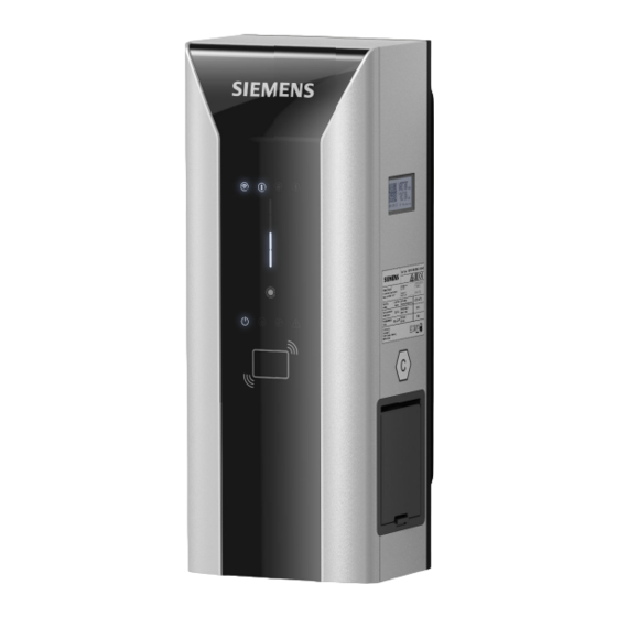
- Page 1 Edition 08/2023 OPERATING INSTRUCTIONS VersiCharge VersiCharge AC Wallbox - ERK (8EM1310-F.0.-...) www.siemens.com/versicharge...
- Page 2 Introduction Safety information Description Mounting / Installing / VersiCharge AC Wallbox Connecting Operating Instructions ERK Commissioning Operating Instructions Operation Faults Maintenance and service Service & Support Disposal Technical specifications Appendix Valid as of revision 04.03.02 List of abbreviations 08/2023 A5E51549696-AC...
- Page 3 Note the following: WARNING Siemens products may only be used for the applications described in the catalog and in the relevant technical documentation. If products and components from other manufacturers are used, these must be recommended or approved by Siemens. Proper transport, storage, installation, assembly, commissioning, operation and maintenance are required to ensure that the products operate safely and without any problems.
-
Page 4: Table Of Contents
Table of contents Introduction............................Purpose of this documentation..................Conventions........................Open-source software....................... Safety information..........................General safety information....................Safety during setup, installation and maintenance............. 11 Safety during electrical installation..................12 The five safety rules for electrical work................13 Safety during operation....................14 Security information...................... - Page 5 Error cases........................65 Maintenance and service........................67 Storage and transport....................... 67 Cleaning and maintenance....................67 Maintenance........................Software update....................... 69 Service & Support..........................70 Siemens Industry Support....................70 Disposal.............................. 10.1 Recycling and disposal...................... 71 Technical specifications........................72 11.1 Technical specifications....................Appendix............................
- Page 6 Table of contents Accessories........................74 Installation and maintenance schedule................75 Dimensions of the Wallbox....................77 Information on weights and measures regulations............Retrieving measured values....................81 Transparency software...................... 89 Quality documentation..................... 92 List of abbreviations........................... 93 Abbreviations........................93 Index..............................94 VersiCharge AC Wallbox Operating Instructions ERK Operating Instructions, 08/2023, A5E51549696-AC...
-
Page 7: Introduction
Siemens accepts no liability for the use of the open-source software over and above the intended program sequence, or for any faults caused by modifications to the software. More information on the Open Source Software is available on the Internet (https://support.industry.siemens.com/cs/gb/en/view/109798470). -
Page 8: Safety Information
Safety information General safety information This section provides important, general information on the following topics: • Avoiding accidents or damage to property • Application planning • Mounting and installation • Operation • Maintaining and cleaning the Wallbox • Disposal Read this section carefully and follow the safety regulations. This will minimize safety risks. Make your staff and customers aware of this section. - Page 9 Safety information 2.1 General safety information Areas of application of the device • Charging electrically operated vehicles in public and semi-public areas • Charging stations for depots, car parks, public parking areas, and retail • Stations for car-to-go projects Intended use The device is used to charge batteries in fully electric and plug-in hybrid vehicles.
- Page 10 Safety information 2.1 General safety information Safety equipment To rule out hazardous conditions, it is strictly prohibited to change, remove, bypass, or override safety devices. Failure to follow these instructions may result in hazardous situations that could cause death or serious injury. Risk of explosion and fire Do not store or use highly flammable liquids that produce flammable vapors, such as gasoline or ethanol, in the proximity of the Wallbox.
-
Page 11: Safety During Setup, Installation And Maintenance
Safety information 2.2 Safety during setup, installation and maintenance Safety during setup, installation and maintenance To avoid any danger, only qualified personnel may set up and mount the Wallbox. The Wallbox must be in a deenergized state. Follow the installation and assembly instructions provided. -
Page 12: Safety During Electrical Installation
Safety information 2.3 Safety during electrical installation Safety during electrical installation Observe the following points for the electrical installation. The electrical connection of the Wallbox may only be performed by skilled electricians and may only be carried out in a deenergized state. -
Page 13: The Five Safety Rules For Electrical Work
Safety information 2.4 The five safety rules for electrical work The five safety rules for electrical work The European standard EN 50110‑1 "Operation of electrical installations" prescribes safety rules for electrical work on and in electrical installations. To ensure the safety of persons and property in accordance with the standards, always comply with the following safety rules. -
Page 14: Safety During Operation
In order to protect plants, systems, machines, and networks against cyber threats, it is necessary to implement – and continuously maintain – a holistic, state-of-the-art industrial security concept. Siemens’ products and solutions constitute one element of such a concept. Operators of the Wallbox are responsible for preventing unauthorized access to their plants, systems, machines and networks. -
Page 15: Safety-Relevant Symbols
Safety information 2.7 Safety-relevant symbols Password Assign a secure password during commissioning to protect the Wallbox against unauthorized access. To do this, follow the current recommendations for security in the information technology when selecting the password. Safety-relevant symbols Symbols for the Wallbox The following table explains icons than may be located on your product, on its packaging, or in the accompanying documentation. - Page 16 Safety information 2.7 Safety-relevant symbols Table 2-1 Standard EN 17186 EN 62196-2 Type 2 Vehicle coupling ≤ 480 V AC RMS, and vehicle plug 3-phase EN 62196-2 Type 2 Plug and socket ≤ 480 V AC RMS, 3-phase Figure 2-1 EN 17186 symbols on Wallbox and charging plug VersiCharge AC Wallbox Operating Instructions ERK Operating Instructions, 08/2023, A5E51549696-AC...
-
Page 17: Description
• Connectable charging socket type 2 or permanently installed charging cable with type 2 coupling according to IEC 62196 • Communication via Open Charge Point Protocol (OCPP) In conjunction with a Siemens backend system (e.g. Siemens Device Management), the Wallbox offers additional functions: • Connection and control via network, smartphones, and digital terminals •... -
Page 18: Structure Of The Wallbox
Description 3.2 Structure of the Wallbox Structure of the Wallbox The following figure shows the structure of the Wallbox from the front and the rear. Socket variant VersiCharge AC Wallbox Operating Instructions ERK Operating Instructions, 08/2023, A5E51549696-AC... - Page 19 Description 3.2 Structure of the Wallbox Cable variant ① User interface ② Meter display ③ Nameplate ④ Charging socket or cable variant ⑤ Cable ⑥ Mount point of wall bracket ⑦ Entry of supply cable. ⑧ Entry of communication cable ⑨...
-
Page 20: User Interface Structure
Description 3.3 User interface structure User interface structure ① Wi-Fi status ② Remote control ③ Front panel locked ④ Bluetooth status (not used) ⑤ Multifunction display for charging status / RFID / time delay / error conditions ⑥ Touch button ⑦... -
Page 21: Scope Of Delivery
Description 3.4 Scope of delivery Scope of delivery Scope of delivery The following components are included in the scope of delivery: ① 1x Wallbox (here as symbol drawing for lockable charging socket type 2 or permanently installed charging cable with type 2 coupling according to IEC 62196) ②... -
Page 22: Meter
Description 3.6 Sealing on the meter Meter The Wallbox has an integrated BSM active energy meter. The meter value is available in the Sifinity Go app / Device Manager and can be read from the display. Sealing on the meter The meter sealing serves as access/manufacturer protection. -
Page 23: Sealing On The Maintenance Door
Description 3.7 Sealing on the maintenance door Internal sealing: All meter relevant connectors are protected and the AC output interface is covered. The meter has the seal identification BZR or a sealing by sticker ① Lead seal ② Sticker longitudinal ③... -
Page 24: Sealing On The Housing
The following graphics show the position and use of the seals with VersiCharge. Supplier seals 1. External sealing: Invalidity sticker or seal in the production line ① Siemens seal Figure 3-5 Sticker/seal Figure 3-6 Siemens seal (dimensions in millimeters) VersiCharge AC Wallbox Operating Instructions ERK Operating Instructions, 08/2023, A5E51549696-AC... -
Page 25: Identification Of The Device Erk
Description 3.9 Identification of the device ERK 2. Nameplate: A nameplate made of self-destructive material is used. ① Nameplate with self-destructive property Identification of the device ERK Nameplate The nameplate is located on the outside of the Wallbox and provides information on the device ID, serial number, metrology ID, national prototype test certificate, data matrix code (contains serial number) and the most important connection data. - Page 26 Imin 0.25A AC Schlagfestigkeit IK10 Current Range Imax 32A AC Impact Class Ausgangsleistung Schutzart Max.22kW IP54 Output IP code SIEMENS AG Siemenspromenade 10 91058 Erlangen, Deutschland Class A Made in China ① Type number ② Serial number ③ Revision number ④...
-
Page 27: Display
Description 3.10 Display Article number The article number has the following structure: ① ② ③ ④ ⑤ ⑥ ⑦ ⑧ ⑨ ⑩ 0= Default version ① 3= 32 A 3-phase / 22 kW ② F = Wallbox compliant with calibration laws ③ H= Socket type 2, outlet right ④... -
Page 28: Mounting / Installing / Connecting
Mounting / Installing / Connecting Safety measures during assembly General information Charging of electric cars must guarantee high electrical performance over long periods. The pre-installation of the power supply and the installation of the Wallbox must comply with the power requirements. To ensure that these requirements are fulfilled correctly, these installation instructions are intended for qualified and trained electricians. -
Page 29: Preparations For Mounting
Mounting / Installing / Connecting 4.3 Assembly procedure Preparations for mounting Requirements • Follow the national legal requirements for the mounting and electrical installation. • Installation site: – The wall is even and load-bearing – When mounting on a column or anywhere else, observe the applicable installation and mounting information. - Page 30 Mounting / Installing / Connecting 4.3 Assembly procedure WARNING Risk of accident Risk of accident through a non-secured Wallbox. • Do not put the Wallbox down unattended. • Place or lay down the Wallbox and its parts in such a way that the Wallbox and its parts cannot tip over or fall down.
- Page 31 Mounting / Installing / Connecting 4.3 Assembly procedure Mounting the wall bracket 1. Remove the wall bracket from the Wallbox. Figure 4-1 Removing the wall bracket 2. Align the wall bracket to the mounting surface using a spirit level. Use the wall bracket to mark the mounting holes.
-
Page 32: Requirements For The Electrical Connection
Also note the regulations in place for upstream protection from transient overvoltages (e.g. through lightning), for example, by using SPDs (Surge Protection Device) according to IEC 60364-7-722. The free Siemens SIMARIS design software supports you in planning and dimensioning the connection, including the dimensioning of the connecting cables Planning (https://new.siemens.com/global/en/products/energy/medium-voltage/simaris/simaris- design.html). -
Page 33: Wiring Position
Mounting / Installing / Connecting 4.5 Wiring position Wiring position Hook the Wallbox into the upper and lower notch of the wall bracket. VersiCharge AC Wallbox Operating Instructions ERK Operating Instructions, 08/2023, A5E51549696-AC... -
Page 34: Connecting The Supply Cable
Mounting / Installing / Connecting 4.6 Connecting the supply cable Remove protective cover: Remove the protective cover of the Wallbox by pressing the two clips upwards to obtain access to the electronics. Connecting the supply cable Select the cable cross-section according to laying type, load and voltage drop: NOTE 3-phase connection Wallboxes with article number 8EM131.-3.0.-.. - Page 35 Mounting / Installing / Connecting 4.6 Connecting the supply cable Procedure DANGER Risk of electric shock When connecting the Wallbox, pay attention to the five safety rules (see also The five safety rules for electrical work (Page 13)). To connect the supply cable, proceed as follows: 1.
- Page 36 Mounting / Installing / Connecting 4.6 Connecting the supply cable ① Cable entry ② Ferrite core ③ Supply line at the terminal block Figure 4-4 Infeed of Wallbox 8EM1310-..0.-…. NOTE Ribbon cable firmly plugged in During installation, make sure that the ribbon cable is firmly plugged into the P3 connector.
- Page 37 NOTE Cable type Siemens recommends the use of copper cables; the warranty does not cover use of a wrong cable type which could break during installation. VersiCharge AC Wallbox Operating Instructions ERK Operating Instructions, 08/2023, A5E51549696-AC...
- Page 38 Mounting / Installing / Connecting 4.6 Connecting the supply cable 2. Tighten the nuts of the cable gland by hand to ensure a tight seal and strain relief. Use the supplied reducer for cables with 9 to 15 mm outer diameter. Check that the seal is sitting correctly.
-
Page 39: Limiting The Charging Current
Mounting / Installing / Connecting 4.7 Limiting the charging current Limiting the charging current The rated current of the respective model (see nameplate) is set for the Wallbox in the factory. This can be limited further using the selector switch placed on the charging controller, see the figure below. -
Page 40: Connecting The Communication Cable
Mounting / Installing / Connecting 4.8 Connecting the communication cable Connecting the communication cable Connection of the communication cables Proceed as follows to connect the communication cables for Ethernet or Modbus: NOTE Connect the plugs after insertion Only mount the RJ45 plug or Modbus RTU plug after insertion through the sealing insert. Mounting the plug before insertion results in damage to the sealing insert. - Page 41 Mounting / Installing / Connecting 4.8 Connecting the communication cable Connection plugs and DIP switches The following figure shows the connection plugs and DIP switches for the communication cables. ① RJ45 socket for Ethernet/ModbusTCP ② Seal insert ③ RS485 interface for Modbus RTU ④...
-
Page 42: Closing The Wallbox
Mounting / Installing / Connecting 4.9 Closing the Wallbox Closing the Wallbox 1. Place the cover over the electronic modules and fasten it with flexible clips 2. Attach the protective cover for the electronics again (not in illustration). Check that the seal is sitting correctly. - Page 43 Mounting / Installing / Connecting 4.9 Closing the Wallbox VersiCharge AC Wallbox Operating Instructions ERK Operating Instructions, 08/2023, A5E51549696-AC...
-
Page 44: Switching On And Testing
Mounting / Installing / Connecting 4.10 Switching on and testing 4.10 Switching on and testing Procedure for switching on and checking the Wallbox Perform the following steps to switch on and check the charging unit. 1. Switch on the power supply of the Wallbox supply line. 2. -
Page 45: Commissioning
Commissioning Commissioning with PC or mobile device For the integrated functions of the Wallbox, you need an Internet connection to connect to Siemens Device Management. The connection is set up during the commissioning described here. Preparing commissioning Commission the Wallbox either with your mobile device using the Sifinity Go App or with a PC tool. - Page 46 If you want to change network settings such as SSID and password after the Wallbox has been successfully connected to Siemens Device Management, proceed as follows: 1. Delete the link of the Wallbox with Siemens Device Management via the Sifinity Go App or via VersiCharge Siemens Cloud (https://versicharge.emobility.siemens.cloud/).
-
Page 47: Notes On Setting Up The Communication Connection
5.2 Notes on setting up the communication connection Notes on setting up the communication connection 5.2.1 Required open ports These open ports are required for communication with the Siemens Device Management, logging server and OCPP server: Domain name Ports Application layer... -
Page 48: Wi-Fi Connection
8EM131x-xxxxx-3xx2 are delivered equipped with a factory-fitted SIM card for the connection to the Siemens Device Management system (and also to the Siemens OCPP backend if appropriate). Note that the mobile wireless data connection can incur costs. - Page 49 SIM card must be activated before insertion. NOTE Devices that are delivered with a factory-fitted SIM card (8EM131x-xxxxx-3xx2) require the following parameters to establish a connection to the Siemens Device Management System: • Modem dial string: *99# • APN: cu.siemens.global •...
-
Page 50: Overview Of Modbus, Rs485 And Ethernet
• Take on the function of Child Modbus devices • Provide data in real time via the Modbus protocol Modbus map The Modbus map is available on request from the Download Center (see also Siemens Industry Online Support (https://support.industry.siemens.com/cs/de/de/view/109814359)). VersiCharge AC Wallbox Operating Instructions ERK... -
Page 51: Setting Communication
• OCPP-based server: Directly via the server The management of RFID cards via Admin cards in the local, preconfigured list is described under Releasing or locking RFID cards. For the Modbus method, see Siemens Industry Online Support (https://support.industry.siemens.com/cs/de/de/view/109814359). For the OCPP-based method, see OCPP Implementation Guide (https://support.industry.siemens.com/cs/ww/en/view/109814941). - Page 52 Commissioning 5.3 Managing and using RFID Using RFID With RFID cards, you authenticate yourself to start or end a charging process. The procedure is described in section Charging (Page 58). The supplied RFID User cards are not released. The next section describes the management of the RFID User cards.
- Page 53 Commissioning 5.3 Managing and using RFID Supported RFID cards For authentication, the Wallbox has an integrated RFID reader that is activated ex works. The following table lists the supported chip types. Table 5-1 Supported chip types Card series Memory Security Supported protocols MIFARE Classic 1 K, 4 K Crypto1...
- Page 54 Commissioning 5.3 Managing and using RFID 3. Hold another User card in front of the RFID reader to release or lock User cards in the preconfigured list. If necessary, repeat this process as often as desired. 4. Hold an Admin card in front of the RFID reader to end management of RFID cards. An acoustic signal is emitted.
-
Page 55: Operation
Operation Status displays Display Table 6-1 Display Description Action Wallbox is ready for operation Figure Lights up white Vehicle connected Figure Lights up white Charging in progress Figure Lights up white After switch-on, the charger will go Connect PC or mobile device for commissioning to Access Point mode Figure Flashes white No Wi-Fi reception... - Page 56 Display Description Action Charger is connected to router. Strong Wi-Fi. Figure Lights up green Attempting to connect to Siemens Device Management Figure Flashes blue Ready for operation (with successful connection and registration in Siemens Device Management) Figure Lights up white...
- Page 57 Operation 6.1 Status displays Display Description Action 4 h delay Wait until charging process starts. Figure Flashes white 6 h delay Wait until charging process starts. Figure Flashes white 8 h delay Wait until charging process starts. Figure Flashes white Press the touch button to set a time Press the touch button once for a 2-hour delay, twice for a delay.
-
Page 58: Charging
Operation 6.2 Charging Charging Safety instructions during the charging process DANGER Risk of electric shock and fire Touching live parts may cause electric shock or even death. Defective connectors or cables may cause fire. • Do not kink or squeeze the charging cable. Do not draw the charging cable over sharp edges or hot surfaces. - Page 59 Operation 6.2 Charging Different models The charging process is described for the socket version with type 2 charging port. The procedure is largely identical for the following version. • Fixed charging cables type 2 The following deviations may occur during the sequence: •...
- Page 60 Operation 6.2 Charging Completing the charging You or the electric vehicle can stop charging at any time. NOTE Option: Permanently installed charging cables After charging, place the permanently installed charging cable in the holder provided. Cables that are not stowed may cause the following hazards: •...
-
Page 61: Faults
Repeating commissioning/logoff from Siemens Device Management If this is necessary, follow these steps: 1. With the device switched on, delete the link of the Wallbox to the Siemens Device Management – via the Sifinity Go App under Account > My Charger > Deregister Charger or –... -
Page 62: General Troubleshooting Guide
Wallbox is found in the software. Wi-Fi Led flashes blue 1. The Wallbox is connected to the Internet and is waiting to connect to the Siemens Cloud. 2. Please note that the Wallbox can be connected via OCPP. -
Page 63: Troubleshooting Guide For Technical Support
Faults 7.3 Troubleshooting Guide for Technical Support The Wallbox cable winder or the stele is damaged or broken 1. Switch off the Wallbox. 2. Put the Wallbox aside. 3. Open a service ticket. NOTE If the error persists, follow the Technical Support Troubleshooting Guide and call Technical Support if necessary. - Page 64 Faults 7.3 Troubleshooting Guide for Technical Support ① 1 fault ② 2 fault ③ 3fault ④ 4fault ⑤ Status LED - Error Figure 7-1 Visual HMI Elements VersiCharge AC Wallbox Operating Instructions ERK Operating Instructions, 08/2023, A5E51549696-AC...
-
Page 65: Error Cases
Faults 7.4 Error cases Error cases Some error cases are relevant for the VersiCharge meter to supply valid and reliable energy measurement values as correct input for billing and invoicing. The handling of these error cases by the VersiCharge system is described here. •... - Page 66 Faults 7.4 Error cases Meter error If communication with the Bauer meter is disrupted, for example, by a CRC error before the start of the charging process, the charging process is not created. If the meter error occurs after a successfully started charging process, there are two scenarios.
-
Page 67: Maintenance And Service
Maintenance and service Storage and transport Observe the following general conditions when storing and transporting the Wallbox: • The permissible storage temperature of the Wallbox is -25 °C to +80 °C. • The permissible air humidity is 5 to 98%, no condensation. • The Wallbox may only be transported in the transport packaging provided for this purpose using the supplied safety and shock-absorbing materials. -
Page 68: Maintenance
Maintenance and service 8.3 Maintenance Cleaning guidelines • Do not use solvents or corrosive or abrasive detergents. • Use a mild, non-corrosive cleaning agent, e.g. dishwashing detergent, even if heavily soiled. • Use a wet cloth to clean the Wallbox outside and dry it. •... -
Page 69: Software Update
Siemens makes software updates available as part of continuous function extensions and improvements. The software updates are installed automatically. Make sure that the Internet connection is available. Also read the information about this at the Siemens Care Remote Service on the Internet (https://siemens.com/emobility-care) VersiCharge AC Wallbox Operating Instructions ERK... -
Page 70: Service & Support
Product supportAll the information and extensive know-how on your product, technical specifications, FAQs, certificates, downloads, and manuals. • mySupportYour personal working area in Siemens Industry Online Support for notifications, support queries, and configurable documents. This information is provided by Siemens Industry Online Support (https://support.industry.siemens.com/cs/ww/)on the internet. -
Page 71: Disposal
Disposal 10.1 Recycling and disposal Disposal of the packaging The packaging of the Wallbox does not contain any hazardous substances. Send the packaging for recycling in accordance with the applicable regulations in your country. Disposal of the Wallbox For the environmentally friendly recycling and disposal of your old device, contact a certified disposal service for electronic scrap. -
Page 72: Technical Specifications
Technical specifications 11.1 Technical specifications Performance features and options Designation VersiCharge AC Wallbox ERK Charging mode according to IEC 61851-1 Mode 3 Connection to vehicle according to IEC 62196-2 8EM1310-..H..-…. : Socket Type 2 8EM1310-..J..-…. : Permanently connected charging cable (7 Electrical data Connection voltage 8EM1310-3...: 3~ 230/400 V AC (-20% ... - Page 73 Technical specifications 11.1 Technical specifications Designation VersiCharge AC Wallbox ERK Ambient temperature storage -25 ... 60°C Mechanical ambient conditions Electromagnetic ambient conditions Relative humidity 5 ... 98% (no condensation) Max. installation altitude 2000 m above sea level Degree of protection (IP) according to IEC 60529 8EM1310-..H..-..
-
Page 74: A Appendix
SIM card Accessories Protection of persons and wiring Siemens offers residual current circuit breakers and miniature circuit breakers as accessories. The trained electrician makes the selection according to the local conditions and regulations at the place of use. The following table shows possible combinations of circuit breakers in connection with the Wallbox variant, including rated current setting. -
Page 75: Installation And Maintenance Schedule
The recommended products relate to household applications. MCBs of the 5SY4 and 5SY6 series are recommended for systems with multiple Wallboxes for additional protection. Additional information is available here (https://mall.industry.siemens.com/). Installation and maintenance schedule Introduction Depending on the area of application, perform the general cleaning work and maintenance work every 6 months. - Page 76 • Housing Commissioning with the mobile app / PC tool Check • Fault message • Backend connection (e.g. Siemens Device Management) • SIM card Cleaning Check charging sockets or charging cables • Charging cable and charge coupling for damage Measurements acc. to DIN VDE, e.g.: •...
-
Page 77: Dimensions Of The Wallbox
Appendix A.4 Dimensions of the Wallbox Action Installa Commis Mainten Duration tion/asse sioning ance in min. mbly Setup time Indication of the next test date Read out meter readings Travel time *Scope and duration may vary as they depend on local regulations. Dimensions of the Wallbox Dimension drawing The following graphic shows the general dimensions of the Wallbox charging unit regardless... -
Page 78: Information On Weights And Measures Regulations
Appendix A.5 Information on weights and measures regulations Note that the dimensions of the Wallbox with permanently installed charging cable and Type 2 coupling according to IEC 62196 differ and you will need additional space. Figure A-2 Distances at the wall and between adjacent Wallboxes Information on weights and measures regulations Eichrechtliche Hinweise und Verwenderauflage Messrichtigkeitshinweise gemäß... - Page 79 Appendix A.5 Information on weights and measures regulations 5. Der Verwender muss die aus der Ladeeinrichtung ausgelesenen, signierten Datenpakete - entsprechend der Paginierung lückenlos dauerhaft (auch) auf diesem Zweck gewidmeter Hardware in seinem Besitz speichern („dedizierter Speicher“), - für berechtigte Dritte verfügbar halten (Betriebspflicht des Speichers.).
- Page 80 Appendix A.5 Information on weights and measures regulations 3. Fordert der Kunde einen Beweis der richtigen Übernahme der Messergebnisse aus der Ladeeinrichtung in die Rechnung, ist der Messwertverwender entsprechend MessEG, § 33, Abs. (3) verpflichtet, diesen zu erbringen. Fordert der Kunde einen vertrauenswürdigen dauerhaften Nachweis gem.
-
Page 81: Retrieving Measured Values
Has.To.Be as an example. NOTE Make sure that the backend used is integrated with VersiCharge. For this, read the information included with the product or provided on the Internet (https://siemens.com/versicharge). VersiCharge AC Wallbox Operating Instructions ERK Operating Instructions, 08/2023, A5E51549696-AC... - Page 82 Appendix A.6 Retrieving measured values Login to the provider 1. Open an Internet browser 2. Enter https://certifications.htb.solutions/ in the address line. 3. Click "Enter" 4. Sign in with your credentials Figure A-3 Login VersiCharge AC Wallbox Operating Instructions ERK Operating Instructions, 08/2023, A5E51549696-AC...
- Page 83 Appendix A.6 Retrieving measured values Charging stations 1. Select the tab Dashboard 2. Click DETAILS in the field Ladestationen Figure A-4 Charging stations VersiCharge AC Wallbox Operating Instructions ERK Operating Instructions, 08/2023, A5E51549696-AC...
- Page 84 Appendix A.6 Retrieving measured values Charging column Click on the data field for the corresponding charging column. Figure A-5 Charging column VersiCharge AC Wallbox Operating Instructions ERK Operating Instructions, 08/2023, A5E51549696-AC...
- Page 85 Appendix A.6 Retrieving measured values Charging processes Click the arrow next to DETAILS in the field Ladevorgänge. Figure A-6 Charging processes VersiCharge AC Wallbox Operating Instructions ERK Operating Instructions, 08/2023, A5E51549696-AC...
- Page 86 Appendix A.6 Retrieving measured values Selecting the charging process Select the charging process and click on the right of the appropriate field. Figure A-7 Charging process VersiCharge AC Wallbox Operating Instructions ERK Operating Instructions, 08/2023, A5E51549696-AC...
- Page 87 Appendix A.6 Retrieving measured values Signed measured values Click the Signierte Messwerte tab. Figure A-8 Signed measured values VersiCharge AC Wallbox Operating Instructions ERK Operating Instructions, 08/2023, A5E51549696-AC...
- Page 88 Appendix A.6 Retrieving measured values Downloading the measured values Click on the arrow to download the signed measured values of the charging process. Figure A-9 Download Result The file with the signed measured values in *.xml format, the selected charge process, is stored locally on your device.
-
Page 89: Transparency Software
Appendix A.7 Transparency software Transparency software Installation and setup of the Transparency software To install and commission the application, proceed as follows: 1. Download the transparency software version 1.1.0 (https://www.safe- ev.de/de/transparenzsoftware.php) or 1.2.0 to your computer. 2. Extract this file into any folder. 3. - Page 90 Appendix A.7 Transparency software Notes on operating the Transparency software 1. Open the installed application. 2. Select the tab "Datei - Öffnen". 3. Select the previously loaded measured value file (*.xml) with Öffnen. 4. The data value set content of the transaction and the public key are displayed unchecked. 5.
- Page 91 Appendix A.7 Transparency software Additional information In the - Details - tab, the relevant charging station metadata are displayed. Figure A-11 Transparency software More information VersiCharge AC Wallbox Operating Instructions ERK Operating Instructions, 08/2023, A5E51549696-AC...
-
Page 92: Quality Documentation
The declaration of conformity is kept available for the competent authorities at: Siemens AG Smart Infrastructure eMobility Siemenspromenade 10, 91058 Erlangen, Germany These files are also available for download on the Siemens Industry Online Support (https://support.industry.siemens.com/cs/de/en/view/109794281) pages, under "Declaration of Conformity". VersiCharge AC Wallbox Operating Instructions ERK Operating Instructions, 08/2023, A5E51549696-AC... -
Page 93: List Of Abbreviations
List of abbreviations Abbreviations Alternating current Alternating current Access Point Name Gateway access point Direct current Direct current DGUV Deutsche Gesetzliche Unfallversicherung German statutory accident insurance Electrostatic Discharge Electrostatic discharge Frequently Asked Questions Frequently asked questions Fehlerstromschutzschalter Residual current circuit breaker International Electronical Commission International standardization commission under private law... -
Page 94: Index
Index Service plan, 75 Siemens Care Remote Service, 69 Amperage:, 39 Siemens Device Management, 45 App, 45 Status displays, 55 Support, 70 CE marking, 92 Charging, 58 VersiCharge Configurator, 46 checklist, 75 DIP switch settings, 41 EC Declaration of Conformity, 92... - Page 95 More information http://www.siemens.com Siemens AG Smart Infrastructure eMobility Siemenspromenade 10 91058 Erlangen, Germany...