
Related Manuals for Yamaha FX HO 2019


Summary of Contents for Yamaha FX HO 2019
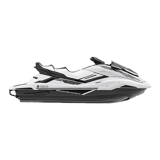
- Page 1 2019 WaveRunner FX HO FX Cruiser HO OWNER’S/OPERATOR’S MANUAL Read this manual carefully before operating this watercraft. F3V-F8199-70-E0...
- Page 2 Read this manual carefully before operating this watercraft. This manual should stay with the WaveRunner if it is sold.
- Page 3 Name of PWC Manufacturer: YAMAHA MOTOR CO., LTD. Address: 2500 Shingai, Iwata, Shizuoka 438-8501, Japan Name of Authorised Representative: YAMAHA MOTOR EUROPE N.V. Address: Koolhovenlaan 101, 1119 NC Schiphol-Rijk, The Netherlands Name of Notified Body for exhaust and noise emission assessment: SNCH...
- Page 4 Important manual information EJU30193 EJU40411 To the owner/operator Thank you for choosing a Yamaha watercraft. Because Yamaha has a policy of continuing This owner’s/operator’s manual contains in- product improvement, this product may not formation you will need for proper operation, be exactly as described in this owner’s/oper-...
-
Page 5: Table Of Contents
Control function operation ..... 24 Cleat ..........50 Watercraft control functions ..24 Pull-up cleats (FX Cruiser HO)..51 Yamaha Security System ....24 Storage compartments ....51 Engine stop switch ......25 Fire extinguisher holder and cover ... 54 Engine shut-off switch .... - Page 6 Table of contents Draining the bilge water ....59 Long-term storage ......89 Draining the bilge water on land ..59 Cleaning ........... 89 Draining the bilge water on water ..60 Lubrication ........89 Transporting on a trailer ....61 Rustproofing........
-
Page 7: General And Important Labels
Craft Identification Number (CIN), and engine serial number in the spaces pro- vided for assistance when ordering spare parts from a Yamaha dealer. Also record and keep these ID numbers in a separate place in case your watercraft is stolen. -
Page 8: Manufactured Date Label
A full explana- tion of this information is given in the relevant sections of this manual. 1 Manufactured date label location 1 Builder’s plate location YAMAHA MOTOR CO., LTD. 2500 Shingai, Iwata, Shizuoka, Japan WATERCRAFT DESIGN CATEGORY : C MAXIMUM CAPACITIES Max. - Page 9 General and important labels TIP: The significant wave height is the mean height of the highest one-third of the waves, which approximately corresponds to the wave height estimated by an experienced observer. However, some waves will be dou- ble this height.
-
Page 10: Important Labels
General and important labels EJU30453 Important labels Read the following labels before using this watercraft. If have any questions, consult a Yamaha dealer. -
Page 11: Warning Labels
General and important labels EJU35914 Warning labels If any of these labels are damaged or missing, contact a Yamaha dealer for replacements. - Page 12 General and important labels F1B-U41B1-21 F2S-U41B1-20...
- Page 13 General and important labels F1S-U415B-11 F1B-U415B-11 (F1S-U41E1-11) (F2S-U41E1-10) (F1S-U41E1-11) (F2S-U41E1-10) F0V-U41DB-12...
-
Page 14: Other Labels
General and important labels EJU44221 Other labels F1B-U41F5-21 B42-F817K-00 (F1S-U41E1-11) (F2S-U41E1-10) 6EY-43394-00 FX Cruiser HO B16-F811S-00... -
Page 15: Safety Information
Limitations on who may The safe use and operation of this water- operate the watercraft craft is dependent upon the use of proper Yamaha recommends a minimum operator riding techniques, as well as upon the age of 16 years old. -
Page 16: Cruising Limitations
Safety information ers to avoid you or understand where you EJU43321 Cruising limitations are going. Scan constantly for people, objects, and Avoid areas with submerged objects or other watercraft. Be alert for conditions shallow water. that limit your visibility or block your vision Do not release the throttle lever when trying ... -
Page 17: Operation Requirements
Safety information chance of hitting a submerged object, EJU43130 Operation requirements which could result in injury. All riders must wear a personal flotation de- vice (PFD) that is approved by the appro- priate authorities and is suitable for personal watercraft use. Wear protective clothing. - Page 18 Safety information in certain kinds of accidents and that it in front of them or to the handgrip provid- could injure you in others. A helmet is designed to provide some head The operator and passengers should al- protection. Although helmets cannot pro- ways keep their feet on the floor of the foot- tect against all foreseeable impacts, a hel- well when the watercraft is in motion.
-
Page 19: Recommended Equipment
Scan carefully for swimmers and stay away be used as an emergency signal. Contact a from swimming areas. Swimmers are hard Yamaha dealer for more information. to see and you could accidentally hit some- Watch one in the water. -
Page 20: Hazard Information
Always operate the watercraft in an This model is equipped with the Yamaha open area. Engine Management System (YEMS) that Do not touch the hot muffler or engine dur- includes an off-throttle steering (OTS) sys- ... - Page 21 Safety information ther direction, although some movement Stop the engine and remove the clip from may occur. the engine shut-off switch before removing any debris or weeds, which may have col- lected around the jet intake. x100 13.6V 1 “N” (Neutral position) To avoid rear-end collisions while operat- ...
-
Page 22: Wakeboarding And Water-Skiing
Safety information Normal swimwear does not adequately EJU30957 Wakeboarding and water- protect against forceful water entry into the skiing rectum or vagina. The person being pulled You can use the watercraft for wakeboarding should wear a wetsuit bottom or clothing or water-skiing if it has the seating capacity to that provides equivalent protection. -
Page 23: Safe Boating Rules
EJU30971 Safe boating rules and weather conditions. Your Yamaha watercraft is legally considered When preparing to pull a wakeboarder or a powerboat. Operation of the watercraft water-skier, operate the watercraft at the... -
Page 24: Enjoy Your Watercraft Responsibly
Safety information When you ride responsibly, with respect and EJU30992 Enjoy your watercraft courtesy for others, you help ensure that our responsibly waterways stay open for the enjoyment of a You share the areas you enjoy when riding variety of recreational opportunities. your watercraft with others and with nature. -
Page 25: Description
The left side of the watercraft when facing forward. Bilge water Water that has collected in the engine compartment. Yamaha Engine Management System (YEMS) YEMS is an integrated, computerized management system that controls and adjusts ignition timing, fuel injection, engine diagnostics, and the off-throttle steering (OTS) system. -
Page 26: Location Of Main Components
Description EJU31012 Location of main components Exterior 1 Hood 2 Beverage holder (page 53) 3 Pull-up cleat (FX Cruiser HO) (page 51) 4 Footwell 5 Optional part mounting bracket 6 Fuel filler cap (page 56) 7 Front seat (page 48) 8 Rear seat (page 48) 9 Cooling water pilot outlet (page 28) 10 Bow eye (page 50) - Page 27 Description 1 Handgrip (page 49) 2 Cleat (page 50) 3 Stern storage compartment (page 52) 4 Reboarding grip (page 49) 5 Boarding platform 6 Stern eye (page 50) 7 Intake grate 8 Stern drain plug (page 59) 9 Ride plate 10 Jet thrust nozzle 11 Reverse gate (page 29) 12 Reboarding step (page 49)
- Page 28 Description 1 Handlebar 12 “SET” switch (page 37) 2 Rearview mirror 13 “NO-WAKE MODE” switch (page 34) 3 RiDE lever (page 29) 14 Tilt lever (page 27) 4 Start switch (page 25) 15 Glove compartment (page 52) 5 Engine shut-off switch (page 25) 16 “ALARM MUTE”...
- Page 29 Description Engine compartment 1 Dipstick (page 58) 2 Engine oil filler cap (page 58) 3 Electrical box 4 Battery (page 66) 5 Removable watertight storage compart- ment (page 53) 6 Spark plug/Ignition coil 7 Fuel tank 8 Water separator (page 28) 9 Air filter case 10 Engine cover...
-
Page 30: Control Function Operation
EJU45100 Yamaha Security System setting The default setting for the PIN is “1234”. The The Yamaha Security System setting can be PIN can also be changed. (See page 43 for in- confirmed by the lock or unlock mode indica- formation on changing the PIN.) tor on the multifunction information center. -
Page 31: Engine Stop Switch
Control function operation vent accidental starting or unauthorized op- EJU31153 Engine stop switch “ ” eration by children or others. The engine stop switch (red button) stops the engine when the switch is pushed. EJU42323 Start switch “ ” 1 Engine stop switch ECJ01311 NOTICE EJU31164... -
Page 32: Throttle Lever
1 Start switch The engine will not start under any of the fol- lowing conditions: Lock mode of the Yamaha Security System has been selected. (See page 24 for Yamaha Security System setting proce- 1 RiDE lever dures.) -
Page 33: Adjustable Tilt Steering System
This model is equipped with the Yamaha En- gine Management System (YEMS) that in- cludes an off-throttle steering (OTS) system. -
Page 34: Cooling Water Pilot Outlet
Control function operation (2) Make sure that the tilt lever returns to its TIP: original position and that the handlebars It will take about 60 seconds for the water are securely locked in place. to reach the outlet after the engine is start- Water discharge may not be constant ... -
Page 35: Watercraft Operation
Watercraft operation reverse, and the “R” (reverse) shift indi- EJU40014 Watercraft operation functions cator will be displayed. EJU43154 Shift system EWJ01773 WARNING Make sure that there are no obstacles or people behind you before shifting into reverse. Do not touch the reverse gate while the ... - Page 36 Watercraft operation and the “N” (neutral) shift indicator will be dis- To shift into forward: played. (1) Release the RiDE lever. (2) Squeeze the throttle lever. The reverse gate will rise completely, the engine speed will increase, the watercraft will start moving forward, and the “F”...
-
Page 37: Electric Trim System
Watercraft operation This function can be used only for forward TIP: operation of the watercraft. If the RiDE lever is squeezed while the throttle TIP: lever is squeezed, the watercraft will slow down, and once stopped, move in reverse. When the watercraft is moving in reverse or ... - Page 38 Watercraft operation the bow. The trim angle can be adjusted Vertical movement of the bow will be reduced in the range of the trim settings –2 to +2. and the watercraft will get up on plane more quickly when accelerating. 1 “TRIM/T.D.E.”...
-
Page 39: Watercraft Operation Modes
Watercraft operation increase. The engine speed can be ad- EJU40002 Watercraft operation modes justed to two levels: +1 and +2. EJU45061 Reverse assist The reverse assist is a function for temporar- ily increasing the engine speed when moving in reverse, such as to enter the water smoothly when launching the watercraft from a trailer. -
Page 40: No-Wake Mode
Watercraft operation This function can be used only when the wa- TIP: tercraft is in neutral. While the T.D.E. is activated, the “N” (neutral) TIP: shift indicator will be displayed and “0” will be While the watercraft is shifted into forward, displayed on the speedometer. -
Page 41: Drive Control Mode
Watercraft operation Activating and deactivating the no-wake tings: “No Wake –1”, “No Wake” (stan- mode dard setting), and “No Wake +1”. The activation of the no-wake mode can be To deactivate the no-wake mode: confirmed by the no-wake mode indicator on Perform one of the following operations. - Page 42 Watercraft operation (2) Tap the drive control mode indicator on To operate the watercraft using the drive con- the multifunction information center. trol mode: (3) If the drive control mode screen is (1) Release the throttle lever and let the en- locked, the PIN entry screen will be dis- gine speed return to idle.
-
Page 43: Cruise Assist
Watercraft operation and the acceleration setting under “Ac- To unlock the drive control mode screen: cel.” (1) Release the throttle lever and let the en- gine speed return to idle. (2) Tap the drive control mode indicator on Speed Accel. the multifunction information center. - Page 44 Watercraft operation Activating and deactivating the cruise as- squeezed further than the position at sist which the cruise assist was set. Activation of the cruise assist can be con- TIP: firmed by the cruise assist indicator on the Check the multifunction information center to multifunction information center.
-
Page 45: Instrument Operation
TIP: and then turn on the center again. If the mes- The multifunction information center does not sage remains displayed, consult a Yamaha receive operation input while the watercraft is dealer. moving. Before operating the multifunction... -
Page 46: Operation Buttons
Instrument operation symbol in the warning bar that is displayed EJU45121 Operation buttons when a warning is activated. This model is equipped with operation but- tons that can be used in addition to touching the multifunction information center. x100 13.6V 1 Screen tab bar 1 “MENU SCROLL”... -
Page 47: Status Area
Instrument operation EJU45141 TIP: Status area If a warning is activated or a malfunction is The areas on the left and right sides of the detected, the warning bar will be displayed multifunction information center that show instead of the tachometer number display. the watercraft information and the tachome- Shift indicator ter at the bottom of the multifunction informa-... -
Page 48: Information Screen
Instrument operation function information center will automatically Tap “Fuel Info ”, “ Trip Info”, or “ ” to switch to the home screen. switch the displayed screen. TIP: The display units for the distances and fuel amounts are selected according to the dis- play units of the multifunction information center. -
Page 49: Drive Control Mode Screen
Instrument operation Fuel information (“Fuel Info”) Selecting the display language Displaying the time since the last mainte- nance Resetting the settings, trip information, and Av MPG fuel information Gal Used Gp H Trip Info PIN Settings Display Unit Language 1 Average fuel consumption per gallon or liter... - Page 50 Instrument operation The color of the segments shown in the bar “Metric”: Distances are shown in kilome- graphs and the color that indicates selected ters, speeds are shown in km/h, and fuel items can be changed. amounts are shown in liters. Unit Metric US Unit...
-
Page 51: Engine Lock Screen
(2) Tap the “Confirm Reset” button to reset The engine lock screen shows the setting the number of hours of operation. screen for the Yamaha Security System in the Resetting the settings, trip information, center display. (See page 24 for Yamaha Se- and fuel information (“Reset”) - Page 52 “Low”, and the buzzer sounds intermittently. If the check engine warning is activated, im- mediately reduce the engine speed, return to shore, and have a Yamaha dealer check the engine. TIP: Tap “ ” to display a description of the x100 13.6V...
- Page 53 “ ” is shown, and the buzz- er sounds intermittently. If a warning is activated, have the watercraft serviced by a Yamaha dealer as soon as pos- sible. TIP: TIP: While the engine overheat warning is acti- ...
-
Page 54: Equipment Operation
Equipment operation To install the rear seat: EJU40335 Equipment (1) Insert the projections on the front of the EJU45210 seat into the stays on the deck. Seats The front and rear seats are removable. Remove the seats to access the engine com- partment and removable watertight storage compartment. -
Page 55: Handgrip
Equipment operation (3) Pull the seat rearward and remove it. EJU31364 Handgrip The handgrip is used when boarding the wa- tercraft from the water and when the spotter is facing rearward. WARNING! Do not use the handgrip to lift the watercraft. The handgrip is not designed to support the watercraft’s weight. -
Page 56: Bow Eye
Equipment operation when released. WARNING! Do not use the EJU34873 Bow eye reboarding step to lift the watercraft. The The bow eye is used to attach a rope to the reboarding step is not designed to support watercraft when transporting, mooring, or the watercraft’s weight. -
Page 57: Pull-Up Cleats (Fx Cruiser Ho)
Equipment operation could fall, which could result in severe in- jects that must be kept dry, put them in a wa- jury. terproof bag. [EWJ01511] Make sure that the storage compartments are closed securely before operating the wa- tercraft. EJU45250 Bow storage compartment The bow storage compartment is located un- der the hood. - Page 58 Equipment operation To close the bow storage compartment: Glove compartment: Push the rear of the hood down to securely Capacity: lock it in place. 17.0 L (4.5 US gal, 3.7 Imp.gal) Load limit: 1.0 kg (2 lb) To close the glove compartment: Lower the lid, and then hook the glove com- partment latch.
- Page 59 Equipment operation To open the stern storage compartment: the stern storage compartment while the Unhook the stern storage compartment latch rope is attached to the cleat. on both sides, and then open the lid. 1 Ski rope slot 1 Stern storage compartment latch EJU35175 Beverage holder The beverage holder is located near the star-...
-
Page 60: Fire Extinguisher Holder And Cover
Equipment operation To open the removable watertight storage EJU42391 Fire extinguisher holder and cover compartment: The fire extinguisher holder and cover are lo- (1) Remove the rear seat. (See page 48 for cated in the bow storage compartment. seat removal and installation proce- To use the fire extinguisher holder and cover: dures.) (1) Pull the hood latch rearward, and then lift... -
Page 61: Optional Part Mounting Bracket
Equipment operation hood is securely closed before using the watercraft. EJU45291 Optional part mounting bracket A mounting bracket for installing optional parts is located near the port (left) side of the multifunction information center. 1 Optional part mounting bracket Load limit: 1.0 kg (2.2 lb) -
Page 62: Operation And Handling Requirements
All ethanol blends containing more than 10% ethanol can cause fuel system damage or engine performance problems. Yamaha does not recommend gasohol con- taining methanol because it can cause fuel system damage and engine performance problems. - Page 63 Operation and handling requirements of sparks, open flames, or other sources Do not leave the watercraft with a full of ignition. tank in direct sunlight. (2) Place the watercraft in a well-ventilated area and in a horizontal position. (3) Remove the seats, and then check the fuel level.
-
Page 64: Engine Oil Requirements
(5) If the engine oil level is significantly the engine oil can cause serious engine above the maximum level mark, consult damage. a Yamaha dealer. If the engine oil level is below the minimum level mark, add en- To check the engine oil level: gine oil. -
Page 65: Draining The Bilge Water
Operation and handling requirements (6) Loosen the engine oil filler cap and re- EJU40022 Draining the bilge water move it. ECJ01302 NOTICE Do not run the engine at full throttle when bilge water remains in the engine com- partment. The bilge water can splash into the engine, which can result in severe damage. -
Page 66: Draining The Bilge Water On Water
Operation and handling requirements drain plugs could be damaged, allow- engine compartment can splash into the ing water to enter the engine compart- engine, which can result in severe dam- ment. Check the O-rings on the stern age. [ECJ00554] drain plugs and make sure that the plugs are tightened securely before launching the watercraft. -
Page 67: Transporting On A Trailer
Operation and handling requirements EJU42432 Transporting on a trailer When transporting the watercraft on a trailer, secure the tie downs to the trailer through the bow eye and stern eyes. NOTICE: Do not at- tach ropes or tie downs to any part of the watercraft other than the bow eye and stern eyes to secure the watercraft to the trailer. -
Page 68: First-Time Operation
First-time operation EJU36666 Engine break-in ECJ00432 NOTICE Failure to perform the engine break-in could result in reduced engine life or even severe engine damage. The engine break-in is essential to allow the various components of the engine to wear and polish themselves to the correct operat- ing clearances. -
Page 69: Pre-Operation Checks
RiDE lever Check the RiDE lever for proper operation. Throttle lever Check the throttle lever for proper operation. Check the Yamaha Security System for proper op- Yamaha Security System eration. Engine shut-off cord (lan- Check the engine shut-off cord (lanyard) for dam- yard) age. - Page 70 Pre-operation checks ITEM ROUTINE PAGE Jet thrust nozzle and re- Check the jet thrust nozzle and reverse gate for verse gate damage. Check the stern drain plugs for damage and foreign Stern drain plugs material and check that they are securely installed. Hood Check that the hood is securely closed.
-
Page 71: Pre-Operation Check Points
Pre-operation checks Make sure that there is no damage inside the EJU32282 Pre-operation check points engine compartment. EJU42384 Pre-launch checks Perform the pre-launch checks in the pre-op- eration checklist while the watercraft is on land. To perform the pre-launch checks: (1) Remove the seats and removable water- tight storage compartment. - Page 72 Pre-operation checks the dipstick. (See page 58 for information on EJU32424 Water separator check checking the engine oil level.) Make sure that no water has collected in the water separator. If water has collected in the water separator, drain it. (See page 28 for in- formation on draining the water separator.) 1 Dipstick 1 Water separator...
- Page 73 Pre-operation checks aged, obstructed, or not connected prop- whole range, and that the free play is not ex- erly. cessive. [EWJ00452] 1 Negative (–) battery terminal: Black lead Turn the handlebars as far as possible to the 2 Positive (+) battery terminal: Red lead right and left to make sure that the jet thrust 3 Breather hose nozzle moves as the handlebars are turned,...
- Page 74 Pre-operation checks right and left fully turned positions of the jet EJU40363 Adjustable tilt steering system checks thrust nozzle. Operate the adjustable tilt steering system several times to make sure that operation is smooth throughout the whole range. Also, make sure that the handlebars are securely locked in place.
- Page 75 (See pages 25 to 25 for in- formation on operating each switch.) EJU45350 Yamaha Security System check Make sure that the Yamaha Security System operates properly. (See page 24 for Yamaha Security System setting procedures.) 1 Clip EJU32664...
- Page 76 (See page 51 for with this watercraft. If you do not have one, information on the storage compartments.) contact a Yamaha dealer or a fire extinguish- er dealer to obtain one meeting the proper EJU41082 Fire extinguisher holder, cover, and band specifications.
-
Page 77: Post-Launch Checks
Pre-operation checks Securely install the stern drain plugs by tight- EJU44250 Stern drain plug checks ening them until they stop. Loosen the stern drain plugs and remove them, and then make sure that the plugs and O-rings on the plugs are not damaged and that there is no foreign material on the threads or O-rings on the plugs. - Page 78 Pre-operation checks safe distance away from people, objects, EJU40553 Cooling water pilot outlet check and other watercraft. [EWJ01860] Make sure that water is discharged from the cooling water pilot outlet while the engine is running. (See page 28 for information on the cooling water pilot outlet.) x100 13.6V...
-
Page 79: Operation
Consult a EJU33006 Learning to operate your watercraft Yamaha dealer about any control or func- Before operating the watercraft, always per- tion that you do not fully understand. Fail- form the pre-operation checks listed on page ure to understand how the controls work 63. -
Page 80: Riding Position
To start the engine: (1) If the lock mode is selected for the Yamaha Security System setting, select the unlock mode. (See page 24 for Yamaha Security System setting proce- dures.) -
Page 81: Stopping The Engine
Operation is attached correctly. If the engine to avoid. A collision could result in severe shut-off cord (lanyard) is not attached injury or death. [EWJ00602] correctly, it may not pull free when the operator falls off, allowing the water- craft to continue to run and cause an accident. -
Page 82: Turning The Watercraft
Operation (idle) position. (See page 29 for shift system Steering control depends on the combination operation procedures.) of handlebar position and the amount of throttle. Water sucked in through the intake grate is pressurized by the impeller in the jet pump. As the pressurized water is expelled from the pump through the jet thrust nozzle, it creates thrust to move and steer the watercraft. -
Page 83: Stopping The Watercraft
1 Reverse gate This model is equipped with the Yamaha En- gine Management System (YEMS) that in- cludes an off-throttle steering (OTS) system. It will activate at planing speeds should you attempt to steer the watercraft after releasing the throttle lever (see condition C above). -
Page 84: Operating The Watercraft In Reverse Or Neutral
Operation proximately 110 m (360 ft) after the throttle le- EJU43445 Operating the watercraft in reverse or ver is released or the engine is stopped, neutral although this distance will vary depending on Operating in reverse many factors, including gross weight, water When the RiDE lever is squeezed, the “R”... -
Page 85: Boarding The Watercraft
Operation current location. (See page 29 for shift sys- bles or sand could be sucked into the jet tem operation procedures.) intake, causing impeller damage and en- gine overheating. [ECJ00473] 60 cm (2 ft) x100 13.6V 1 “N” (Neutral position) EJU42461 Boarding alone (1) From the rear of the watercraft, lower the... - Page 86 Operation (3) Pull yourself up onto the boarding plat- holding on to the person in front of them form and grasp the handgrip, and then or to the handgrip provided. move to the seat and sit astride. Before boarding the watercraft, make ...
-
Page 87: Starting Off
Operation (4) Have the first passenger board using the are securely holding on to the person in same procedure as the operator, place front of them or to the handgrip provided. their feet on the floor of the footwell, and securely hold on to the operator. -
Page 88: Capsized Watercraft
Operation from objects—you need throttle to (2) Attach the engine shut-off cord (lanyard) steer. to your left wrist, and then attach the clip to the engine shut-off switch. ECJ01341 (3) Push the watercraft away from the dock, NOTICE grip the handlebars with both hands, and Never run the engine in water that is less place both feet on the floor of the foot- than 60 cm (2 ft) deep from the bottom of... -
Page 89: Beaching And Docking The Watercraft
Operation on the gunwale with your other hand or (2) Release the throttle lever to reduce your foot. speed about 110 m (360 ft) before you reach the intended beaching area. (3) Slowly approach the beach using the throttle lever and RiDE lever to control the watercraft speed. -
Page 90: After Removing The Watercraft From The Water
Operation EJU40242 After removing the watercraft from the water ECJ01311 NOTICE Do not run the engine over 4000 r/min on land. Also, do not run the engine for more than 15 seconds without supplying water, otherwise the engine could overheat. After operating and removing the watercraft from the water, promptly discharge the re- maining water from the cooling water pas-... -
Page 91: Care And Storage
Care and storage (4) Connect the garden hose adapter to a EJU37146 Post-operation care garden hose. EWJ00331 WARNING Always place the watercraft upright in a horizontal position when storing it, other- wise fuel could leak out into the engine or engine compartment, which could create a fire hazard. -
Page 92: Cleaning The Watercraft
Care and storage ter flows out continually from the jet (2) Rinse the engine and engine compart- thrust nozzle. ment with a small amount of water. NOTICE: Do not use high-pressure water when rinsing the engine or en- gine compartment as severe engine damage could result. - Page 93 2 Minimum level mark If distilled water was added, check the bat- tery voltage. It is recommended to have a Yamaha dealer check the battery voltage and charge the bat- tery. If you charge the battery yourself, be sure to read and follow the instructions pro- vided with the battery tester and charger you 1 Negative (–) battery terminal: Black lead...
- Page 94 (3) Apply water-resistant grease to the bat- tery terminals. Recommended water-resistant grease: YAMALUBE MARINE GREASE/Yamaha Grease A (4) Store the battery in a cool, dry place. NOTICE: Storing the battery in an un- charged condition can cause perma- nent battery damage. Check the battery periodically.
-
Page 95: Long-Term Storage
Storage for long periods of time, such as win- ter storage, requires preventive maintenance to ensure against deterioration. It is advisable to have the watercraft serviced by a Yamaha dealer prior to storage. TIP: However, the following procedures can be Disconnect the electric trim rod from the ball performed easily by the owner. -
Page 96: Maintenance
1 Tool bag See a Yamaha dealer for genuine Yamaha re- 2 Screwdriver 3 Garden hose adapter placement parts and optional accessories 4 10/12 mm box wrench designed for your watercraft. - Page 97 Maintenance (3) Lift up the engine cover to remove it. 1 Engine cover To install the engine cover: (1) Place the engine cover in its original po- sition, and then push it down. (2) Install the engine cover screws. (3) Securely install the seats in their original positions.
-
Page 98: Periodic Maintenance Chart
Yamaha dealer perform the checks in the following chart. However, maintenance may need to be performed more frequently depending on your operating conditions. If you have any questions, consult a Yamaha dealer. This “√” mark indicates items to be checked and serviced by a Yamaha dealer. Initial Thereafter every... - Page 99 Maintenance Initial Thereafter every 50 hours hours or hours or Item Operation Page or 12 10 hours months months months Check for exhaust leak- √ Exhaust system age, and check hoses and — clamps Check breather hose and √ Breather hose —...
-
Page 100: Engine Oil And Oil Filter
Do not run the engine with too much or not enough oil in the engine, otherwise the en- gine could be damaged. It is recommended to have a Yamaha dealer change the engine oil and the engine oil filter. However, if you choose to change the oil and... -
Page 101: Specifications
Specifications Ignition system: EJU34543 Specifications T.C.I. Watercraft capacity: Spark plug (NGK): LFR6A Maximum people on board: Spark plug gap: 3 person 0.8–0.9 mm (0.031–0.035 in) Maximum load capacity: Battery capacity: 240 kg (530 lb) 12 V, 19 Ah Dimensions and weight: Charging system: Length: Flywheel magneto... -
Page 102: Trouble Recovery
Troubleshooting If you have any trouble with your watercraft, use the troubleshooting chart to check for the possible cause. If you cannot find the cause, consult a Yamaha dealer. EJU45390 Troubleshooting chart Confirm the possible cause and remedy, and then refer to the applicable page. - Page 103 Fuel Fuel tank empty Refill as soon as pos- larly or stalls sible Stale or contaminat- Have serviced by — Yamaha dealer Fuel tank Water or dirt present Have serviced by — Yamaha dealer Spark plug Fouled or defective Have serviced by —...
- Page 104 Cavitation Jet intake clogged Clean Impeller damaged or Have serviced by worn Yamaha dealer Engine over- Engine speed reduc- Clean jet intake and heat warning tion control activated cool engine Oil pressure Engine speed reduc-...
-
Page 105: Emergency Procedures
Trouble recovery ways stop the engine before beaching the EJU34625 Emergency procedures watercraft. EJU44590 Cleaning the jet intake and impeller EWJ00783 WARNING Before attempting to remove weeds or de- bris from the jet intake or impeller area, shut the engine off and remove the clip from the engine shut-off switch. -
Page 106: Raising The Reverse Gate
After raising the reverse gate so that the wa- tercraft can move forward, immediately re- turn to shore and have a Yamaha dealer 1 Reverse gate service the watercraft. 2 Forward position... -
Page 107: Replacing The Fuses
Trouble recovery (1) Connect the positive (+) jumper cable to EJU43482 Replacing the fuses the positive (+) battery terminals of both If a fuse is blown, replace it with the proper batteries. fuse. (2) Connect one end of the negative (–) jumper cable to the negative (–) battery terminal of the booster battery. - Page 108 Trouble recovery (3) Remove the electrical box cover. Install the spare fuse, and then tighten the screws. 1 Electrical box cover 2 Lock 1 Electronic throttle valve fuse 3 Projection 2 Fuel pump fuse 3 Main relay drive fuse (4) While pushing both sides of the fuse box 4 Main fuse cover inward, pull the cover toward the 5 Spare fuse...
-
Page 109: Towing The Watercraft
If the fuse immediately blows again, the elec- back into the engine, causing severe trical system may be defective. If this occurs, engine damage. have a Yamaha dealer service the watercraft. [ECJ01331] Tow the watercraft at 8 km/h (5 mph) or less. EJU34716... - Page 110 (See page 59 for informa- tion on draining the bilge water.) (3) Have the watercraft serviced by a Yamaha dealer as soon as possible. NOTICE: Be sure to have a Yamaha dealer inspect the watercraft. Other- wise, serious engine damage could result.
-
Page 111: Index
Index Engine oil and oil filter ......94 Adjustable tilt steering system ....27 Engine oil level check....... 66 Adjustable tilt steering system checks ..68 Engine oil requirements ......58 After removing the watercraft from the Engine serial number ......... 1 water............. - Page 112 Watercraft characteristics ......14 Reverse assist.......... 33 Watercraft control functions..... 24 RiDE lever..........26 Watercraft operation functions ....29 RiDE lever checks ........68 Watercraft operation modes ....33 Riding position ......... 74 Rustproofing ..........89 Yamaha Security System ......24...
- Page 113 Index Yamaha Security System check ....69 Yamaha Security System setting ..... 24...
- Page 114 Although the sensors and recorded data will vary by model, the main data points are: Engine status and engine performance data This data will be uploaded only when a special Yamaha diagnostic tool is attached to the en- gine, such as when maintenance checks or service procedures are performed. Engine data uploaded will be handled appropriately according to the following Privacy Policy.
- Page 116 Printed in U.S.A. September 2018–0.7 × 1 CR...