Table of Contents
Advertisement
Advertisement
Table of Contents

Related Manuals for Asus ROG STRIX B760-I GAMING WIFI


Summary of Contents for Asus ROG STRIX B760-I GAMING WIFI
- Page 1 ROG STRIX B760-I GAMING WIFI...
- Page 2 Product warranty or service will not be extended if: (1) the product is repaired, modified or altered, unless such repair, modification of alteration is authorized in writing by ASUS; or (2) the serial number of the product is defaced or missing.
-
Page 3: Table Of Contents
Contents Safety information ...................... iv About this guide ......................v ROG STRIX B760-I GAMING WIFI specifications summary ........vi Package contents ......................x Chapter 1: Product Introduction Before you proceed ................... 1-1 Motherboard layout ..................1-2 Chapter 2: Basic Installation Building your PC system ................ -
Page 4: Safety Information
Safety information Electrical safety • To prevent electrical shock hazard, disconnect the power cable from the electrical outlet before relocating the system. • When adding or removing devices to or from the system, ensure that the power cables for the devices are unplugged before the signal cables are connected. If possible, disconnect all power cables from the existing system before you add a device. -
Page 5: About This Guide
Refer to the following sources for additional information and for product and software updates. ASUS website The ASUS website (www.asus.com) provides updated information on ASUS hardware and software products. Optional documentation Your product package may include optional documentation, such as warranty flyers, that may have been added by your dealer. -
Page 6: Rog Strix B760-I Gaming Wifi Specifications Summary
* Supported memory types, data rate (speed), and number of DRAM modules may vary depending on the CPU types and memory configuration, for more information refer to www.asus.com for the memory support list. ** Non-ECC, un-buffered DDR5 memory supports On-Die ECC function. - Page 7 ROG STRIX B760-I GAMING WIFI specifications summary Rear USB (Total 8 ports) 1 x USB 3.2 Gen 2x2 port (1 x USB Type-C ® 4 x USB 3.2 Gen 1 ports (3 x Type-A +1 x USB Type-C ® 3 x USB 2.0 ports (3 x Type-A) Front USB (Total 5 ports) 1 x USB 3.2 Gen 2 connector (supports USB Type-C...
- Page 8 ROG STRIX B760-I GAMING WIFI specifications summary Miscellaneous 1 x Addressable Gen 2 header 1 x Aura RGB header 1 x Clear CMOS header 1 x Front Panel Audio header (AAFP) Internal I/O connectors 1 x S/PDIF Out header 1 x Speaker header...
- Page 9 Form Factor 6.7 inch x 6.7 inch (17 cm x 17 cm) • Specifications are subject to change without notice. Please refer to the ASUS website for the latest specifications. • MyAsus offers a variety of support features such as helping to troubleshoot issues, optimizing product performance, integrating ASUS software, and recovery drive creation.
-
Page 10: Package Contents
Package contents Check your motherboard package for the following items. Motherboard 1 x ROG STRIX B760-I GAMING WIFI motherboard 2 x SATA 6Gb/s cables Cables 1 x ROG USB 2.0 splitter cable 1 x Panel Cable Additional Cooling Kit 1 x Thermal pad for M.2... -
Page 11: Chapter 1: Product Introduction
• The pin definitions in this chapter are for reference only. The pin names depend on the location of the header/jumper/connector. • For more information on installing your motherboard, please scan the QR code below: ROG STRIX B760-I GAMING WIFI... -
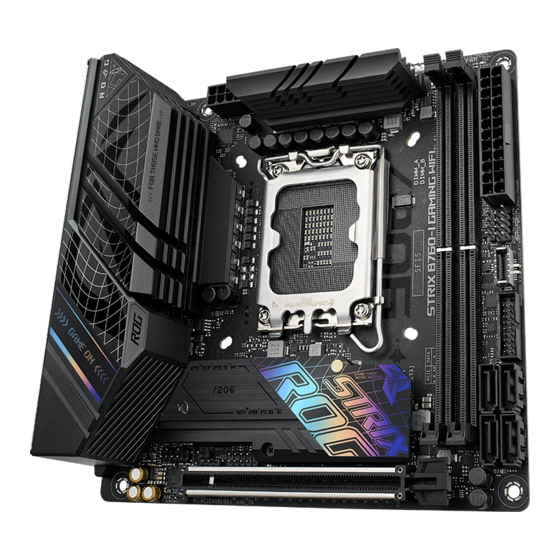
Page 12: Motherboard Layout
Motherboard layout DRAM 17.0cm(6.7in) BOOT RGB HEADER CHA_FAN CPU_FAN AIO_PUMP ADD GEN 2 ATX_12V HDMI_DP DIGI+ USB_11 USB_56 BATT_CON LAN_U32G1_E12 LGA1700 U32G2X2_C1 Ethernet U32G1_E3 256Mb BIOS M.2(WIFI) COM_DEBUG Super Intel ® 2280 2260 B760 AUDIO AAFP CLRTC SPDIF_OUT SATA6G_3 USB_78 SATA6G_4 Audio Codec... - Page 13 1-14 13. RTC Battery header 1-15 14. Clear CMOS header 1-15 15. Front Panel Audio header 1-16 16. S/PDIF Out header 1-16 17. System Panel header 1-17 18. Thermal Sensor header 1-18 19. Q-LEDs 1-18 ROG STRIX B760-I GAMING WIFI...
- Page 14 Contact your retailer immediately if the PnP cap is missing, or if you see any damage to the PnP cap/socket contacts/motherboard components. ASUS will shoulder the cost of repair only if the damage is shipment/ transit-related.
- Page 15 A DDR5 memory module is notched differently from a DDR, DDR2, DDR3, or DDR4 module. DO NOT install a DDR, DDR2, DDR3, or DDR4 memory module to the DDR5 slot. Recommended memory configurations DIMM_A DIMM_A DIMM_B DIMM_B ROG STRIX B760-I GAMING WIFI...
- Page 16 (D/C) from the same vendor. Check with the vendor to get the correct memory modules. • Visit the ASUS website for the latest QVL. Chapter 1: Product Introduction...
- Page 17 Expansion slot Unplug the power cord before adding or removing expansion cards. Failure to do so may cause you physical injury and damage motherboard components. PCIEX16(G5) ROG STRIX B760-I GAMING WIFI...
- Page 18 Fan and Pump headers The Fan and Pump headers allow you to connect fans or pumps to cool the system. CHA_FAN CPU_FAN AIO_PUMP • DO NOT forget to connect the fan cables to the fan headers. Insufficient air flow inside the system may damage the motherboard components. These are not jumpers! Do not place jumper caps on the fan headers! •...
- Page 19 We recommend that you use a PSU with a higher power output when configuring a system with more power-consuming devices. The system may become unstable or may not boot up if the power is inadequate. ROG STRIX B760-I GAMING WIFI...
- Page 20 M.2 slots The M.2 slots allow you to install M.2 devices such as M.2 SSD modules. M.2_2(SOCKET3) M.2_1(SOCKET3) • Intel & 12 Gen Processors: ® - M.2_1 slot (Key M), type 2260/2280 (supports PCIe 4.0 x4 mode). • Intel B760 Chipset: ®...
- Page 21 Intel ® B760 chipset. Before creating a RAID set, refer to the RAID Configuration Guide. You can download the RAID Configuration Guide from the ASUS website. USB 3.2 Gen 2 Type-C Front Panel connector ® The USB 3.2 Gen 2 Type-C connector allows you to connect a USB 3.2 Gen 2...
- Page 22 USB 3.2 Gen 1 header The USB 3.2 Gen 1 header allows you to connect a USB 3.2 Gen 1 module for additional USB 3.2 Gen 1 ports. The USB 3.2 Gen 1 header provides data transfer speeds of up to 5 Gb/s. U32G1_910 PIN 1 USB3+5V...
- Page 23 5V connector is aligned with the 5V header on the motherboard. • The addressable RGB LED strip will only light up when the system is powered on. • The addressable RGB LED strip is purchased separately. ROG STRIX B760-I GAMING WIFI 1-13...
- Page 24 Aura RGB header The Aura RGB header allows you to connect RGB LED strips. RGB_HEADER PIN 1 +12V G R B The Aura RGB header supports 5050 RGB multi-color LED strips (12V/G/R/B), with a maximum power rating of 3A (12V). Before you install or remove any component, ensure that the power supply is switched off or the power cord is detached from the power supply.
- Page 25 If the steps above do not help, remove the onboard button cell battery and move the jumper again to clear the CMOS RTC RAM data. After clearing the CMOS, reinstall the button cell battery. ROG STRIX B760-I GAMING WIFI 1-15...
- Page 26 Front Panel Audio header The Front Panel Audio header is for a chassis-mounted front panel audio I/O module that supports HD Audio. Connect one end of the front panel audio I/O module cable to this header. AAFP PIN 1 HD-audio-compliant pin definition We recommend that you connect a high-definition front panel audio module to this connector to avail of the motherboard’s high-definition audio capability.
- Page 27 (depending on the operating system settings). • Reset button header (RESET) The 2-pin header allows you to connect the chassis-mounted reset button. Press the reset button to reboot the system. ROG STRIX B760-I GAMING WIFI 1-17...
- Page 28 Thermal Sensor header The Thermal Sensor header allows you to connect a sensor to monitor the temperature of the devices and the critical components inside the motherboard. Connect the thermal sensor and place it on the device or the motherboard’s component to detect its temperature.
-
Page 29: Building Your Pc System
CPU designed for LGA1155, LGA1156, LGA1151, and LGA1200 sockets on the LGA1700 socket. • ASUS will not cover damages resulting from incorrect CPU installation/removal, incorrect CPU orientation/placement, or other damages resulting from negligence by the user. Take caution when lifting the load... - Page 30 Ensure to remove the CPU Socket lever protector on the lever latch before locking the lever latch under the retention tab. Failure to do so may cause damages to your system when installing the cooling system. Chapter 2: Basic Installation...
-
Page 31: Cooling System Installation
Ensure to remove the CPU Socket lever protector on the lever latch before installing the cooling system, failure to do so may cause damages to your system. To install a CPU heatsink and fan assembly ROG STRIX B760-I GAMING WIFI... - Page 32 Intel ® 700 series motherboard. • Additional holes for LGA1200 compatible cooling systems are also available on ASUS’ Intel 700 series motherboards, ® however, we still strongly advise consulting with your cooling system vendor or manufacturer on the compatibility and...
- Page 33 • If you wish to install an AIO cooler, we recommend installing the AIO cooler after installing the motherboard into the chassis. AIO_PUMP CPU_FAN CHA_FAN ROG STRIX B760-I GAMING WIFI...
-
Page 34: Dimm Installation
2.1.3 DIMM installation To remove a DIMM Chapter 2: Basic Installation... -
Page 35: Installation
B. Rotate and adjust the M.2 Q-latch so that the handle points away from the M.2 slot. C. Install your M.2 to the M.2 slot. D. Rotate the M.2 Q-Latch clockwise to secure the M.2 in place. ROG STRIX B760-I GAMING WIFI... - Page 36 • To install a type 2260 M.2 A. Remove the plastic film from the thermal pad. B. Install the bundled 2260 standoff to the 2260 length screw hole. C. Install your M.2 to the M.2 slot. D. Secure your M.2 using the bundled screw. Remove the plastic film from the thermal pads on the bottom of the heatsink.
- Page 37 For a 2242 storage device, use the bundled 2242 mounting kit. • Before installing a 2242 M.2 SSD module, ensure that the mounting kit is properly installed with the bigger screw hole on the 2260 standoff. ROG STRIX B760-I GAMING WIFI...
- Page 38 For 2260, 2280 type: This step is optional and only for when you wish to install a 2280 type M.2. Chapter 2: Basic Installation 2-10...
- Page 39 The M.2 is purchased separately. ROG STRIX B760-I GAMING WIFI 2-11...
-
Page 40: Motherboard Installation
2.1.5 Motherboard installation Place the motherboard into the chassis, ensuring that its rear I/O ports are aligned to the chassis’ rear I/O panel. Place four (4) screws into the holes indicated by circles to secure the motherboard to the chassis. DO NOT over tighten the screws! Doing so can damage the motherboard. -
Page 41: Atx Power Connection
2.1.6 ATX power connection Ensure to connect the 8-pin power plug. 2.1.7 SATA device connection ROG STRIX B760-I GAMING WIFI 2-13... -
Page 42: Front I/O Connector
2.1.8 Front I/O connector To install the front panel connector To install USB 3.2 Gen 2 Type-C® connector USB 3.2 Gen 2 Type-C ® This connector will only fit in one orientation. Push the connector until it clicks into place. To install USB 3.2 Gen 1 connector To install USB 2.0 connector USB 2.0... -
Page 43: Expansion Card Installation
2.1.9 Expansion card installation To install PCIe x16 cards ROG STRIX B760-I GAMING WIFI 2-15... -
Page 44: Wi-Fi Moving Antenna Installation
2.1.10 Wi-Fi moving antenna installation Installing the ASUS Wi-Fi moving antenna Connect the bundled ASUS Wi-Fi moving antenna connector to the Wi-Fi ports at the back of the chassis. • Ensure that the ASUS Wi-Fi moving antenna is securely installed to the Wi-Fi ports. -
Page 45: Motherboard Rear And Audio Connections
Activity Link LED Speed LED ACT/LINK SPEED Status Description Status Description No link No link GREEN Linked 100 Mbps / 10 Mbps connection LAN port BLINKING Data activity GREEN 2.5 Gbps connection ORANGE 1 Gbps connection ROG STRIX B760-I GAMING WIFI 2-17... -
Page 46: Audio I/O Connections
** Audio 2, 4, 5.1 or 7.1-channel configuration Port 2-channel 4-channel 5.1-channel 7.1-channel Light Blue Side Speaker (Rear panel) Lime Front Speaker Front Speaker Front Speaker Front Speaker (Rear panel) Pink (Rear panel) Black Rear Speaker Rear Speaker Rear Speaker (Rear panel) Orange Center/... - Page 47 Connect to 4-channel Speakers Connect to 5.1-channel Speakers Connect to 7.1-channel Speakers ROG STRIX B760-I GAMING WIFI 2-19...
-
Page 48: Starting Up For The First Time
Starting up for the first time After making all the connections, replace the system case cover. Ensure that all switches are off. Connect the power cord to the power connector at the back of the system chassis. Connect the power cord to a power outlet that is equipped with a surge protector. Turn on the devices in the following order: Monitor External storage devices (starting with the last device on the chain) -
Page 49: Chapter 3: Bios And Raid Support
Knowing BIOS The new ASUS UEFI BIOS is a Unified Extensible Interface that complies with UEFI architecture, offering a user-friendly interface that goes beyond the traditional keyboard- only BIOS controls to enable a more flexible and convenient mouse input. You can easily navigate the new UEFI BIOS with the same smoothness as your operating system. -
Page 50: Bios Setup Program
BIOS setup program Use the BIOS Setup to update the BIOS or configure its parameters. The BIOS screens include navigation keys and brief onscreen help to guide you in using the BIOS Setup program. Entering BIOS at startup To enter BIOS Setup at startup, press <Delete> or <F2> during the Power-On Self Test (POST). -
Page 51: Asus Ez Flash 3
ASUS EZ Flash 3 The ASUS EZ Flash 3 feature allows you to update the BIOS without using an OS-based utility. Ensure to load the BIOS default settings to ensure system compatibility and stability. Select the Load Optimized Defaults item under the Exit menu or press hotkey <F5>. -
Page 52: Asus Crashfree Bios 3
ASUS CrashFree BIOS 3 The ASUS CrashFree BIOS 3 utility is an auto recovery tool that allows you to restore the BIOS file when it fails or gets corrupted during the updating process. You can restore a corrupted BIOS file using a USB flash drive that contains the BIOS file. -
Page 53: Raid Configurations
For more information on configuring your RAID sets, please refer to the RAID Configuration Guide which you can find at https://www.asus.com/support, or by scanning the QR code. RAID definitions RAID 0 (Data striping) optimizes two identical hard disk drives to read and write data in parallel, interleaved stacks. - Page 54 Chapter 3: BIOS and RAID Support...
-
Page 55: Appendix
RF exposure compliance. HDMI Trademark Notice The terms HDMI, HDMI High-Definition Multimedia Interface, and the HDMI Logo are trademarks or registered trademarks of HDMI Licensing Administrator, Inc. ROG STRIX B760-I GAMING WIFI... - Page 56 Compliance Statement of Innovation, Science and Economic Development Canada (ISED) This device complies with Innovation, Science and Economic Development Canada licence exempt RSS standard(s). Operation is subject to the following two conditions: (1) this device may not cause interference, and (2) this device must accept any interference, including interference that may cause undesired operation of the device.
- Page 57 ASUS follows the green design concept to design and manufacture our products, and makes sure that each stage of the product life cycle of ASUS product is in line with global environmental regulations. In addition, ASUS disclose the relevant information based on regulation requirements.
- Page 58 ASUS products sold in Vietnam, on or after September 23, 2011,meet the requirements of the Vietnam Circular 30/2011/TT-BCT. Các sản phẩm ASUS bán tại Việt Nam, vào ngày 23 tháng 9 năm2011 trở về sau, đều phải đáp ứng các yêu cầu của Thông tư 30/2011/TT-BCT của Việt Nam.
- Page 59 ASUSTek Computer Inc. hereby declares that this device is in compliance with the essential requirements and other relevant provisions of The Radio Equipment Regulations 2017 (S.I. 2017/1206). Full text of UKCA declaration of conformity is available at https://www.asus.com/support/. The WiFi operating in the band 5150-5350MHz shall be restricted to indoor use for the country listed below: UKCA RF Output table (The Radio Equipment Regulations 2017) ®...
- Page 60 постановления на свързаната Директива 2014/53/EC. Пълният текст на ЕС der Richtlinie 2014/53/EU übereinstimmt. Der gesamte Text der EU- декларация за съвместимост е достъпен на адрес Konformitätserklärung ist verfügbar unter: https://www.asus.com/support/. https://www.asus.com/support/. Der WLAN-Betrieb im Band von 5150-5350 MHz ist für die in der unteren WiFi, работеща...
- Page 61 Käesolevaga kinnitab ASUSTek Computer Inc, et seade vastab direktiivi zahtjevima i ostalim odgovarajućim odredbama direktive 2014/53/EU. Cijeli 2014/53/EÜ olulistele nõuetele ja teistele asjakohastele sätetele. EL tekst EU izjave o sukladnosti dostupan je na https://www.asus.com/support/. vastavusdeklaratsiooni täistekst on saadaval veebisaidil https://www.asus.com/support/.
- Page 62 Az EU megfelelőségi nyilatkozat teljes szövegét a ASUSTek Computer Inc. erklærer herved at denne enheten er i samsvar med következő weboldalon tekintheti meg: https://www.asus.com/support/. hovedsaklige krav og andre relevante forskrifter i direktivet 2014/53/EU. Az 5150-5350 MHz-es sávban működő Wi-Fi-t beltéri használatra kell Fullstendig tekst for EU-samsvarserklæringen finnes på:...
- Page 63 Direktive 2014/53/EU. Polno 5150-5350 MHz arasındaki WiFi çalışması, tabloda listelenen ülkeler için iç besedilo izjave EU o skladnosti je na voljo na https://www.asus.com/support/. mekân kullanımıyla kısıtlanacaktır. WiFi, ki deluje v pasovnem območju 5150–5350 MHz, mora biti v državah, Düşük Güç...
- Page 64 ASUSTek Computer Inc. заявляє, що цей пристрій відповідає основним вимогам та іншим відповідним вимогам Директиви 2014 / 53 / EU. Повний текст декларації відповідності нормам ЄС доступний на https://www.asus.com/support/. Робота Wi-Fi на частоті 5150-5350 МГц обмежується використанням у приміщенні для країн, поданих у таблиці нижче: Пристрої...
-
Page 65: Warranty
• ASUS offers a voluntary manufacturer’s Commercial Guarantee. • ASUS dragovoljno nudi komercijalno proizvođačko jamstvo. • ASUS reserves the right to interpret the provisions of the ASUS • ASUS zadržava prava na tumačenje odredbi ASUS komercijalnog Commercial Guarantee. jamstva. •... - Page 66 • ASUS tilbyr som produsent en frivillig kommersiell garanti. • Bảo hành thương mại này của ASUS được cung cấp độc lập và ngoài • ASUS forbeholder seg retten til å tolke bestemmelsene i ASUS sin Bảo đảm pháp lý theo luật định và không có cách nào ảnh hưởng đến kommersielle garanti.
-
Page 67: Asus Contact Information
Address: 1F., No. 15, Lide Rd., Beitou Dist., Taipei City 112 ASUS COMPUTER INTERNATIONAL (America) Address: 48720 Kato Rd., Fremont, CA 94538, USA ASUS COMPUTER GmbH (Germany and Austria) Address: Harkortstrasse 21-23, 40880 Ratingen, Germany ASUSTeK (UK) LIMITED Address: 1st Floor, Sackville House, 143-149 Fenchurch Street, London, EC3M 6BL,...