Siemens SITRANS F Operating Instructions Manual
Ultrasonic flowmeters
Hide thumbs
Also See for SITRANS F:
- Function manual (350 pages) ,
- Instruction manual (306 pages) ,
- Operating instructions manual (278 pages)
Table of Contents
Advertisement
Quick Links
SITRANS F
Ultrasonic flowmeters
SITRANS FST020 IP65 (NEMA 4X)
Operating Instructions
7ME3570 - AC: 1HA400AA0 / 7ME3570 -
DC:1HB400AA0
05/2022
A5E41425845-AC
Introduction
Safety notes
Description
Installing/mounting
Connecting
Commissioning
Operating
Parameter assignment
Service and maintenance
Diagnostics and
troubleshooting
Technical specifications
Dimension drawings
Replacement parts
Modbus communication
Product Documentation
and support
SIMATIC PDM
HMI menu structure
1
2
3
4
5
6
7
8
9
10
11
12
13
A
B
C
D
Advertisement
Table of Contents

Related Manuals for Siemens SITRANS F


Summary of Contents for Siemens SITRANS F
- Page 1 Introduction Safety notes Description SITRANS F Installing/mounting Ultrasonic flowmeters SITRANS FST020 IP65 (NEMA 4X) Connecting Commissioning Operating Instructions Operating Parameter assignment Service and maintenance Diagnostics and troubleshooting Technical specifications Dimension drawings Replacement parts Modbus communication 7ME3570 - AC: 1HA400AA0 / 7ME3570 -...
- Page 2 Note the following: WARNING Siemens products may only be used for the applications described in the catalog and in the relevant technical documentation. If products and components from other manufacturers are used, these must be recommended or approved by Siemens. Proper transport, storage, installation, assembly, commissioning, operation and maintenance are required to ensure that the products operate safely and without any problems.
-
Page 3: Table Of Contents
Table of contents Introduction ............................7 Purpose of this documentation .................... 7 Product compatibility ......................7 Document history ........................ 7 Device documentation package.................... 8 Items supplied ........................8 Checking the consignment....................9 Security information ......................9 Transportation and storage ....................10 Further Information ...................... - Page 4 Table of contents Device nameplates......................26 5.3.1 Device nameplate ......................27 Transmitter power supply, communications and I/O connections ........28 5.4.1 Sensor connections......................28 5.4.2 Connecting the power supply..................... 28 5.4.3 Connecting Inputs/Outputs ....................30 5.4.4 Connection Wiring ......................31 5.4.5 Finishing the transmitter connection (wall mount housing) ..........
- Page 5 Table of contents Inputs and outputs......................59 8.2.1 Digital input........................67 Service and maintenance ........................69 Basic safety notes....................... 69 9.1.1 Impermissible repair of the device ..................69 Recalibration........................69 Maintenance and repair work..................... 69 9.3.1 Maintenance........................69 9.3.2 Service and maintenance information ................70 Return procedure .......................
- Page 6 Table of contents Float byte order ......................... 95 Modbus function codes...................... 96 A.10 Access control........................97 Product Documentation and support ....................99 Product documentation ..................... 99 Technical support......................100 SIMATIC PDM............................101 Commissioning with SIMATIC PDM ................... 101 C.1.1 Overview SIMATIC PDM ....................101 C.1.2 Check SIMATIC PDM version .....................
-
Page 7: Introduction
Introduction Purpose of this documentation These instructions contain all information required to commission and use the device. Read the instructions carefully prior to installation and commissioning. In order to use the device correctly, first review its principle of operation. The instructions are aimed at persons mechanically installing the device, connecting it electronically, configuring the parameters and commissioning it, as well as service and maintenance engineers. -
Page 8: Device Documentation Package
Items supplied The device is delivered as: Wall mount enclosure • FST020 transmitter wall mount enclosure • Siemens Process Instrumentation disk con‐ taining certificates and manuals. Note Supplementary information Supplementary product and production specific certificates are included on the SensorFlash ®... -
Page 9: Checking The Consignment
Siemens’ products and solutions undergo continuous development to make them more secure. Siemens strongly recommends that product updates are applied as soon as they are available and that the latest product versions are used. Use of product versions that are no longer supported, and failure to apply the latest updates may increase customer’s exposure to cyber... -
Page 10: Transportation And Storage
Product information on the Internet The Operating Instructions are available on the documentation disk shipped with the device, and on the Internet on the Siemens homepage, where further information on the range of SITRANS F flowmeters may also be found: Product information on the internet (http://www.siemens.com/flow) -
Page 11: Notes On Warranty
The content reflects the technical status at the time of publishing. Siemens reserves the right to make technical changes in the course of further development. - Page 12 Introduction 1.10 Notes on warranty SITRANS FST020 IP65 (NEMA 4X) Operating Instructions, 05/2022, A5E41425845-AC...
-
Page 13: Safety Notes
Safety notes Precondition for use This device left the factory in good working condition. In order to maintain this status and to ensure safe operation of the device, observe these instructions and all the specifications relevant to safety. Observe the information and symbols on the device. Do not remove any information or symbols from the device. -
Page 14: Conformity With European Directives
Safety notes 2.5 Lithium batteries Conformity with European directives The CE marking on the device symbolizes the conformity with the following European directives: Electromagnetic compatibil‐ Directive of the European Parliament and of the Council on the ity EMC harmonisation of the laws of the Member States relating to elec‐ 2014/30/EU tromagnetic compatibility Low voltage directive LVD... -
Page 15: Description
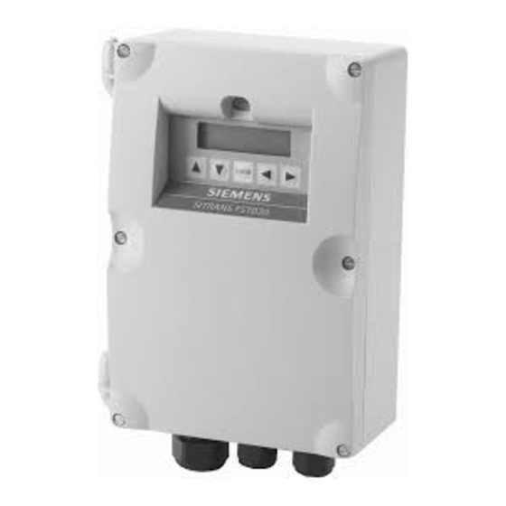
Description Overview SITRANS FST020 ultrasonic flow meter systems consist of a transmitter and a sensor. The following table lists the available combinations of transmitters and sensors. Transmitter Sensor type FST020 FSS200 family DN 15 to DN 10m (0.5" to 360") Design The transmitter reads the measured process values from the sensor and calculates derived values. -
Page 16: Features
Description 3.3 Features Pipe mount kit The Pipe kit is CQO:1012NMB-1. Figure 3-2 Pipe Mounting shown with mounting plate Features • Wall mount IP65 enclosure • Full graphical local display • SensorFlash (SD card) for memory backup, Datalogger and documentation storage (certificates etc.) •... - Page 17 • Simulation of all outputs • Simulation of alarms • Enabling alarms for visibility on all outputs (HMI, status and communication) • Comprehensive diagnostics (Siemens standard) for troubleshooting and sensor checking • Firmware update • Data logging in SensorFlash • Peak indicators •...
- Page 18 Description 3.3 Features SITRANS FST020 IP65 (NEMA 4X) Operating Instructions, 05/2022, A5E41425845-AC...
-
Page 19: Installing/Mounting
Installation instructions (Page 20). Installation location requirements 4.2.1 Environment SITRANS F flowmeters with minimum IP65/NEMA 4X enclosure rating are suitable for indoor and outdoor installations. Process pressure and medium temperature If applicable, make sure that specifications for rated medium temperature (T ) plus ambient temperature that are indicated on the device nameplate / label will not be exceeded. -
Page 20: Normal Environmental Conditions
Installing/mounting 4.3 Installation instructions Sensor Location in piping system The optimum location in the system depends on the presence of excessive gas or air bubbles in the fluid may result in erroneous measurements. Therefore, it is preferred not to install the sensor at the highest point in the system, where gas / air bubbles will be trapped. - Page 21 Installing/mounting 4.3 Installation instructions Prepare holes for the four screws (M6x100 or equivalent). Screw head diameter: max. 13.5 mm; screw shaft diameter: max. 6 mm. • Recommended mounting: Directly to wall or to electrical cabinet back panel. • If alternate mounting surface is used it MUST support four times the weight of the unit. Mounting the enclosure 1.
- Page 22 Installing/mounting 4.3 Installation instructions For installation on 2-inch standpipe use the optional CQO:1012NMB pipe mounting kit. Table 4-1 CQO:1012NMB-1 Mounting Kit Description Mounting Plate U-Bolt Assembly including bracket and nuts 8-32 x 5/8 LG cross round head screws #8 Flat washer #8 Split lock washers 8-32 Hex nut 1.
- Page 23 Installing/mounting 4.3 Installation instructions ① Mounting plate ② Stand pipe ③ Mounting hardware (see table above) ④ U-bolt assembly SITRANS FST020 IP65 (NEMA 4X) Operating Instructions, 05/2022, A5E41425845-AC...
- Page 24 Installing/mounting 4.3 Installation instructions SITRANS FST020 IP65 (NEMA 4X) Operating Instructions, 05/2022, A5E41425845-AC...
-
Page 25: Connecting
Connecting This chapter describes how to wire up the transmitter for operation with a sensor. • Transmitter power supply, communications and I/O connections (Page 28) • Sensor connections (Page 28) • Connecting the power supply (Page 28) • Connecting Inputs/Outputs (Page 30) •... -
Page 26: Disconnecting Device
Connecting 5.3 Device nameplates WARNING Mains supply from building installation overvoltage category 2 A circuit breaker (max. 15 A) must be installed in close proximity to the equipment and within easy reach of the operator. It must be marked as the disconnecting device for the equipment. WARNING DC connection devices The DC power source must be isolated from mains supply. -
Page 27: Device Nameplate
Connecting 5.3 Device nameplates 5.3.1 Device nameplate Transmitter nameplates ① Product name Transmitter product name ② System order no. Device-specific system order number (transmitter and sensor) ③ Transmitter order no. Transmitter replacement order numbers ④ Serial no. Transmitter serial number ⑤... -
Page 28: Transmitter Power Supply, Communications And I/O Connections
Connecting 5.4 Transmitter power supply, communications and I/O connections Transmitter power supply, communications and I/O connections 5.4.1 Sensor connections For sensor connection, see the FSS200 Sensor installation instructions manual. 5.4.2 Connecting the power supply Note If the transmitter is not already mounted and cabling has not been run, proceed to Mounting the Transmitter (Page 20) before connecting power. - Page 29 Connecting 5.4 Transmitter power supply, communications and I/O connections 7. Insert AC or DC power wires into wire entry holes and secure by tightening wire clamp screws using a screwdriver. – For AC - Connect ground to terminal and power to terminals L1 and L2N. –...
-
Page 30: Connecting Inputs/Outputs
Connecting 5.4 Transmitter power supply, communications and I/O connections 9. Tighten cable gland. 10.Connect the power cable to the appropriate power source (100-240 VAC @ 50/60 Hz or 11.5-28.5 VDC) and power up unit. WARNING Circuit limited to 15 Amps The branch circuit must be limited to 15A or damage to the unit and death or serious injury may result. -
Page 31: Connection Wiring
Connecting 5.4 Transmitter power supply, communications and I/O connections 5.4.4 Connection Wiring Terminal Block Wiring These connection diagrams apply to the part numbers listed below. SITRANS FST020 FST020 7ME3570..._... Figure 5-4 Terminal board channels and pin numbers Note 4 to 20 mA current output Channel 2 It is not required to use shielded cables for the pure 4 to 20 mA current output. - Page 32 Connecting 5.4 Transmitter power supply, communications and I/O connections Wiring ① ④ 4 - 20mA output (current source) Digital input (Freeze TOT) ② ⑤ Relay output Digital input (CLR TOT) ③ ⑥ Pulse output Modbus Figure 5-5 Typical FST020 Wiring Connect pulse output to galvanically isolated input Figure 5-6 Alternative pulse output connection with galvanically isolated input...
-
Page 33: Finishing The Transmitter Connection (Wall Mount Housing)
Connecting 5.4 Transmitter power supply, communications and I/O connections If the input is galvanically isolated the polarity does not need to be inverted. Isolated 4-20mA Output TB1-1/2 = 250 Ω typical, 750 Ω maximum = 24 VDC typical / 30 VDC maximum = 4-20mA = Loop wire resistance (both ways) plus User's input load resistance. - Page 34 Connecting 5.4 Transmitter power supply, communications and I/O connections SITRANS FST020 IP65 (NEMA 4X) Operating Instructions, 05/2022, A5E41425845-AC...
-
Page 35: Commissioning
Commissioning This chapter gives instructions to commissioning your device, see Commissioning via local display (Page 37). Furthermore, the device can be commissioned using SIMATIC PDM, see Commissioning with SIMATIC PDM (Page 101). Basic Safety notes WARNING Loss of type of protection Risk of explosion. -
Page 36: General Requirements
Commissioning 6.5 Initial startup General requirements Before commissioning it must be checked that: • The device has been installed and connected in accordance with the guidelines provided in Installing/mounting (Page 19) and Connecting (Page 25). Power-up Power up the device. Local display will show a screen for initial startup (Page 36). Local display The device is commissioned/operated with the touch keypad on the local display. -
Page 37: Commissioning Via Local Display
Commissioning 6.6 Commissioning via local display Start Language Welcome Set date and time Quick commissioning Continue with Quick commissioning wizard First startup wizard is now finished Commissioning via local display 6.6.1 Chapter overview In this chapter it is described how to commission the device via the local display using the Quick commissioning wizard. -
Page 38: Quick Commissioning Wizard (Wizard)
Commissioning 6.6 Commissioning via local display 6.6.2.2 Quick Commissioning wizard (wizard) Start Quick start Quick commissioning Sensor settings Basic configuration Process values Inputs and outputs Sensor settings Copy configuration Process values Inputs and outputs Communication Next Identification Long tag Location Installation date Next Finished... -
Page 39: Sensor Settings Wizard (Wizard)
Commissioning 6.6 Commissioning via local display 6.6.2.4 Sensor settings wizard (wizard) Sensor settings (1) Units settings Units settings Pipe settings Text Options/Description Unit settings Select "Yes" to configure the display units. Unit settings Set the display units of length, temperature, pressure, kinematic viscosity, and density. - Page 40 Commissioning 6.6 Commissioning via local display Sensor settings (2) Pipe settings Pipe class Pipe size Custom Outer diameter + wall thickness Circumference + wall thickness Pipe circumference Outer pipe diameter Wall thickness Select material Custom Wall sound velocity Liner Liner material Liner settings Disturbed flow Inner pipe roughness...
- Page 41 Commissioning 6.6 Commissioning via local display Liner Select "Yes" to configure the liner material. Select "No" to only configure the Inner pipe roughness. Liner material Select the liner material. Liner settings Set the liner sound velocity and thickness. Disturbed flow Define the type of pipe configuration and the distance to the sensor.
- Page 42 Commissioning 6.6 Commissioning via local display Sensor settings (4) Medium settings Medium settings Custom Process parameters Path settings Text Options/Description Medium settings Select "Yes" to configure the medium. Medium settings Select the process medium. Process parameters Set the expected sound velocity (only available if custom process medium is selected) and the process temperature, pressure, kinetic viscosity, and density.
-
Page 43: Process Values Wizard (Menu Item 1.3)
Commissioning 6.6 Commissioning via local display Sensor settings (5) Path settings Installed paths Save settings Finished Start measurement Path geometry Mounting path 1 Path 1 Text Options/Description Path settings Select "YES" to configure the path(s). Installed paths Select the paths installed. Save settings Moves to the next menu item. -
Page 44: Process Values Wizard (Wizard)
Commissioning 6.6 Commissioning via local display ① Wizard name ② Step name / Parameter name ③ View number / Total views in wizard 6.6.2.6 Process values wizard (wizard) Start Quick start Quick commissioning Sensor settings Process values Prioritize Inputs and outputs 1st process value Copy configuration 2st process value... -
Page 45: Inputs/Outputs Wizard
The exact structure of the operating menu is explained in HMI menu structure (Page 115). All items of the menu structure of the device are identified with a unique number. Level 1 of the menu structure is standardized for all Siemens Process Instrumentation devices and covers the following groups: 1. -
Page 46: Navigating The Menu Structure
Commissioning 6.6 Commissioning via local display 5. Security: Contains parameters which describe all security settings of the device. 6. Language: Parameter for changing the language of the local display. Regardless of the language setting, the term for this parameter is always the English term (Language). ①... -
Page 47: Operating
Operating These Operating Instructions describe the operation via the local display (HMI). The device can also be operated via various software. Display views There are six display views, all fully configurable. Use the and the keys to switch between the operator views, Four different types of views are available: •... -
Page 48: Operating The Fst020
PIN codes can be changed in Security (5). Note Lost PIN code If the PIN code is lost, provide Siemens customer support with the transmitter serial number (see nameplate). Siemens customer support will provide a code to be entered in PIN recovery (5.3). Disable access level control If logged in as Expert you can Deactivate user PIN. -
Page 49: Reading The Process Values
Operating 7.3 Operating the FST020 Table 7-2 Diagnostic values Fixed display text Diagnostic value name TRN TEMP. Transmitter internal temperature CURR. OUT (CH2) Ch2 value REYNOLDS NO. Reynolds number P1.SNR UP SNR up path 1 P1.SNR DOWN SNR down path 1 P1.SOUND VEL Sound velocity path 1 P1.DELTA TIME... - Page 50 Operating 7.3 Operating the FST020 Three values 1 value and bargraph Note Bargraphs The bargraph limit values indicate the set lower and upper alarm limits, and the vertical lines in the bargraph indicate the set lower and upper warning limits. 1 value and graph Six values SITRANS FST020 IP65 (NEMA 4X)
-
Page 51: Operating The Totalizer
Operating 7.3 Operating the FST020 7.3.3 Operating the totalizer When totalizer is displayed in the main view, press to access the totalizer operation. Table 7-4 Key functions - totalizer operation Function Exit totalizer operation Select action to perform Select action to perform Perform selected action 7.3.4 Handling alarms... - Page 52 Operating 7.3 Operating the FST020 Table 7-5 Key functions - alarms list view Function Exit alarm list view Select the item above in the list; keep pressing the key to accelerate scrolling up the selec‐ tion list Select the item below in the list; keep pressing the key to accelerate scrolling down the selection list View more information on the selected alarm Press...
-
Page 53: Reading The Diagnostic Values
Operating 7.3 Operating the FST020 7.3.5 Reading the diagnostic values One of the main views can be configured to show six diagnostic values. 7.3.6 Reading / changing parameters 7.3.6.1 Parameter view introduction Depending on your access level, you can read the current value and/or edit the value of the selected parameter. -
Page 54: Changing The Resolution
Operating 7.3 Operating the FST020 Table 7-6 Key functions - editing alphanumeric values Function Select the next left position. If the most left position is selected: exit the parameter edit view without confirming the changes. Keep pressing the key to jump to the most left position. Change the selected number/character. - Page 55 Operating 7.3 Operating the FST020 Parameter list - read only Table 7-7 Key functions - read only Function Exit parameter list No functionality No functionality No functionality Parameter list - editable The help texts describe the possible adjustments of the respective parameters. Table 7-8 Key functions - edit Function...
- Page 56 Operating 7.3 Operating the FST020 Function Scroll down in the list. If the lowermost position is selected: highlight Save settings. Select / deselect option. It is possible to select/deselect multiple alarms to be suppressed. The marked alarms will NOT be suppressed.
-
Page 57: Parameter Assignment
Parameter assignment Multipoint calibration The transmitter provides an additional 20 point piecewise linear calibration table with user selectable input value: volume flow, reynolds number or fluid sound velocity. The table can be configured for either unidirectional or bidirectional calibration. Note Ascending order by reynolds number The datapoints must be entered in ascending order by reynolds number. - Page 58 Parameter assignment 8.1 Multipoint calibration Point Reynolds number Calibration correction Point Reynolds number Calibration correction ① ⑪ 47339 1.0050 54231 0.9930 ② ⑫ 94701 1.0060 102932 0.9934 ③ ⑬ 156034 1.0058 141382 0.9942 ④ ⑭ 238385 1.0062 271843 0.9975 ⑤ ⑮...
-
Page 59: Inputs And Outputs
Parameter assignment 8.2 Inputs and outputs Point Reynolds number Calibration correction ① 47339 1.0050 ② 94701 1.0060 ③ 156034 1.0058 ④ 238385 1.0062 ⑤ 402304 1.0017 ⑥ 532765 0.9971 ⑦ 663226 0.9960 ⑧ 793687 0.9950 ⑨ ⑩ Figure 8-2 User calibration table behavior (unidirectional calibration) Inputs and outputs The available configuration of the hardware functionality of input and output is described in the following table. - Page 60 Parameter assignment 8.2 Inputs and outputs Channel HW configuration SW configuration (fixed when ordering) available to the user Relay output Status Output: • Status signals • Alarm and diagnostics • Flow direction Output • Frequency output • Pulse output Digital input Reset totalizer 1 Digital input Pause/resume totalizer 1...
- Page 61 Parameter assignment 8.2 Inputs and outputs ① Linear control range ② Lower saturation limit ③ Upper saturation limit ④ Lower fault current value ⑤ Recommended setting range for lower fault current ⑥ Recommended setting range for upper fault current ⑦ Measuring range Figure 8-3 Current limits for NAMUR configuration...
- Page 62 Parameter assignment 8.2 Inputs and outputs Positive flow with negative scaling kg /h 400 kg/h 100 kg/h ① Low flow cut-off ② Upper range value ③ Maximum output current ④ Upper fault current ⑤ Lower range value ⑥ Lower saturation limit ⑦...
- Page 63 Parameter assignment 8.2 Inputs and outputs Positive flow across zero with positive scaling 1000 m -250 m ① Lower range value ② Low flow cut-off ③ Upper range value ④ Upper saturation limit ⑤ Lower saturation limit ⑥ Lower fault current ⑦...
- Page 64 Parameter assignment 8.2 Inputs and outputs Bidirectional flow across zero with positive scaling Kg/h ① Lower range value ② Low flow cut-off ③ Upper range value ④ Upper saturation limit ⑤ Lower saturation limit ⑥ Lower fault current ⑦ Span Current output setting •...
- Page 65 Parameter assignment 8.2 Inputs and outputs Bidirectional flow with symmetrical scaling Kg/h ① Upper range value ② Lower range value ③ Low flow cut-off ④ Upper fault current ⑤ Upper saturation limit ⑥ Lower saturation limit ⑦ Span Current output setting •...
- Page 66 Parameter assignment 8.2 Inputs and outputs Example • Pulse output configuration (channels 2 to 4) – Operation mode = Pulse output – Process value = Mass flow – Amount per pulse = 1 kg – Pulse width = 1 ms •...
-
Page 67: Digital Input
Note Alarm class / NAMUR status signals The options depend on the setting selected in Staus icons, either NAMUR status signals or Alarm class (Siemens Standard). 8.2.1 Digital input Digital input If the input signal is activated with a logical signal (15 to 30 V DC) and the Polarity is set to Active high level, the meter carries out an activity selected in the menu Input function: •... - Page 68 Parameter assignment 8.2 Inputs and outputs Note Changing polarity Changing the polarity triggers the signal input to executes the parameterized function. SITRANS FST020 IP65 (NEMA 4X) Operating Instructions, 05/2022, A5E41425845-AC...
-
Page 69: Service And Maintenance
9.1.1 Impermissible repair of the device WARNING Impermissible repair of the device • Repair must be carried out by Siemens authorized personnel only. Recalibration Siemens offers to recalibrate the system. Note For recalibration the transmitter must always be returned with the sensor... -
Page 70: Service And Maintenance Information
Service and maintenance 9.3 Maintenance and repair work An inspection can include check of: • Ambient conditions • Seal integrity of the process connections, cable entries, and cover screws • Reliability of power supply, lightning protection, and grounds • Coupling compound mating the sensors to the pipe surface 9.3.2 Service and maintenance information Service and maintenance information is information about the condition of the device used for... -
Page 71: Return Procedure
To return a product to Siemens, see Returns to Siemens (www.siemens.com/returns-to- siemens). Contact your Siemens representative to clarify if a product is repairable, and how to return it. They can also help with quick repair processing, a repair cost estimate, or a repair report/cause of failure report. - Page 72 Service and maintenance 9.5 Disposal SITRANS FST020 IP65 (NEMA 4X) Operating Instructions, 05/2022, A5E41425845-AC...
-
Page 73: Diagnostics And Troubleshooting
Diagnostic log. The alarm history log can be reset in Reset log. Characteristics of messages The device provides two types of alarm formats, Siemens standard alarm classes and NAMUR status signals, selected in Status icons. The following tables summarize the two types of alarm formats in an overview. -
Page 74: Fault Codes And Corrective Actions
Indicate read only parameters Data exchange • Device is communicating 10.3 Fault codes and corrective actions 10.3.1 Alarm messages Alarms and system messages support both Siemens standard alarm classes and NAMUR status signals. SITRANS FST020 IP65 (NEMA 4X) Operating Instructions, 05/2022, A5E41425845-AC... - Page 75 Diagnostics and troubleshooting 10.3 Fault codes and corrective actions In the following tables the alarm IDs (identification numbers) are listed along with possible causes and directions for corrective action. SITRANS FST020 IP65 (NEMA 4X) Operating Instructions, 05/2022, A5E41425845-AC...
- Page 76 Diagnostics and troubleshooting 10.3 Fault codes and corrective actions SITRANS FST020 IP65 (NEMA 4X) Operating Instructions, 05/2022, A5E41425845-AC...
-
Page 77: Technical Specifications
Technical specifications Note Device specifications Siemens makes every attempt to ensure the accuracy of these specifications but reserves the right to change them at any time. 11.1 Power Table 11-1 Power supply Description Specification Supply voltage • 100 to 240 V AC +10 / -10%, 47 to 63 Hz •... -
Page 78: Outputs
Technical specifications 11.4 Construction 11.3 Outputs Table 11-4 Current output Description Channel 2 Signal range 4 to 20 mA Resolution 0.4 μA Load • Ex i: <470 Ω (HART ≥ 230 Ω) • Non-Ex: <770 Ω (HART ≥ 230 Ω) Time constant (adjustable) 0.0 to 100 s Fault current... -
Page 79: Operating Conditions
Mechanical load 18 to 1000 Hz random, 3.17 g RMS, in all directions, to EN/IEC 68-2-36 Torques Table 11-8 Installation torques Description Torque (Nm) Cable gland to housing (Siemens supplied, metric, NPT) 11.5 Operating conditions Table 11-9 Basic conditions Description Specification... -
Page 80: Approvals
Technical specifications 11.7 SensorFlash 11.6 Approvals UL 61010-1 3rd Edition CAN/CSA-C22.2 No. 61010-1, 3rd Edition EN61010-1: 2010 11.7 SensorFlash Table 11-11 SensorFlash Description Specification SD card (S-300u) SD card (Class 4 with adapter) Capacity 4 GB 4 GB File system support FAT32 / 8.3 FAT32 / 8.3 Temperature range... -
Page 81: Dimension Drawings
Dimension drawings 12.1 Dimension drawing SITRANS FST020 IP65 (NEMA 4X) Operating Instructions, 05/2022, A5E41425845-AC... - Page 82 Dimension drawings 12.1 Dimension drawing SITRANS FST020 IP65 (NEMA 4X) Operating Instructions, 05/2022, A5E41425845-AC...
-
Page 83: Replacement Parts
Replacement parts 13.1 AC Transmitter exploded view Replaceable parts ① Enclosure cover w/screws and display - A5E38846901 ② Cover with screws - A5E41693888 for AC power supply / A5E41693889 for DC power supply ③ AC power supply - 7ML18301MD / DC power supply - 7ML18301ME ④... - Page 84 Replacement parts 13.1 AC Transmitter exploded view Note It is recommended that when replacing the transmitter main board or display board ensure to remove original SD-card from transmitter and re-install after new modules have been installed in order to recall site parameters. The following components are not shown: •...
-
Page 85: Modbus Communication
Modbus communication Modbus addressing model The device allows read/write access to the following standard Modbus RTU data holding register blocks: • Holding registers (ref. 4x address range) The minimum value of a writable holding register can be read by adding 10000 to the Modbus address of the register. - Page 86 Modbus communication A.2 Modbus function codes Function code 3 example Query Slave address 1 byte Function 1 byte Starting Address Hi 1 byte Starting Address Lo 1 byte Quantity of Registers Hi 1 byte Quantity of Registers Lo 1 byte 2 bytes Response Slave address...
- Page 87 Modbus communication A.2 Modbus function codes Function code 16 (Write multiple registers) General exceptions • Writing less than 1 or more than 16 registers => Exception 3 (Illegal data value) • If ByteCount is not exactly 2 times NoOfRegisters => Exception 3 (Illegal data value) •...
- Page 88 Modbus communication A.2 Modbus function codes Starting Address Lo 1 byte Quantity of Registers Hi 1 byte Quantity of Registers Lo 1 byte 2 bytes Example: Set baud rate to 115200 baud (address 529) Query: 1,16,2,17,0,1,2,0,5,70,210 Slave address = 1 (0x01) Function = 16 (0x10) Starting Address Hi, Lo = 2, 17 (0x02,0x11) Quantity of Registers Hi, Lo = 0, 1 (0x00,0x01)
- Page 89 Modbus communication A.2 Modbus function codes Sub- Name Description func‐ tion code (Dec) Return Bus Exception Error The response data field returns the quantity of MODBUS ex‐ Count ception responses returned by the remote device since its last restart, clear counters execution, or power–up. Return Slave Message Count The response data field returns the quantity of messages broadcast or addressed to the remote device that the remote...
-
Page 90: Changing Modbus Communication Settings
Modbus communication A.3 Changing Modbus communication settings Sub-function Hi 1 byte Sub-function Lo 1 byte Data Hi 1 byte Data Lo 1 byte Data Hi 1 byte Data Lo 1 byte 2 bytes Example: Read Return Slave Message Count (address 529) Query: 1,8,0,14,0,0,129,200 Slave address = 1 (0x01) Function = 8 (0x08) -
Page 91: Modbus Communication
Modbus communication A.4 Modbus communication Modbus communication Table A-1 General Modbus settings Modbus Data type / Parameter Description Default Value range / Access register Size in value Setting options level bytes [units] (units register) 8291 Unsigned / Restart com‐ Restarts the communication using •... -
Page 92: Coil Configuration
Modbus communication A.5 Coil configuration Coil configuration The device provides 20 coil definitions which can be configured. Table A-2 Coil configuration Modbus Data type / Parameter Description Default value Value range / Access lev‐ register Size in bytes [units] Setting options (units regis‐... -
Page 93: Modbus Register Mapping
Modbus communication A.6 Modbus register mapping Modbus Data type / Parameter Description Default value Value range / Access lev‐ register Size in bytes [units] Setting options (units regis‐ ter) 10307 Unsigned / 4 Modbus coil bit‐ Bit mask which is compared 0 - 4294967295 Read / write mask 2 against the register value... - Page 94 Modbus communication A.6 Modbus register mapping The device provides means to remap 20 Modbus registers. Table A-3 Modbus register mapping Modbus Data type / Parameter Description Default value Value range / Access register Size in [units] Setting op‐ level bytes (units regis‐...
-
Page 95: Integer Byte Order
Modbus communication A.8 Float byte order Integer byte order The device is able to adjust the byte order of integer values. Table A-4 Integer byte order Modbus Data type / Parameter Description Default value Value range / Access register Size in [units] Setting op‐... -
Page 96: Modbus Function Codes
Modbus communication A.9 Modbus function codes Modbus function codes Table A-6 General Modbus settings Function code Command text Description Read Coils Reads the status of single bit(s) Read Discrete Inputs Reads the status of single input bit(s) Read Holding Registers Reads the binary content of multiple 16-bit registers Read Input Registers Reads the binary content of multiple 16-bit registers... -
Page 97: Access Control
Modbus communication A.10 Access control Manufacturer name 12 bytes SIEMENS Product name 32 bytes SITRANS F Product firmware 16 bytes version 2 bytes A.10 Access control Access control manages whether the Modbus master is allowed to modify device parameters. Reading of parameters is always possible. The general access control rules are: •... - Page 98 Modbus communication A.10 Access control SITRANS FST020 IP65 (NEMA 4X) Operating Instructions, 05/2022, A5E41425845-AC...
-
Page 99: Product Documentation And Support
– "Download as html5, only PC": Open or save the manual in the HTML5 view on your PC You can also find manuals with the Mobile app at Industry Online Support (https:// support.industry.siemens.com/cs/ww/en/sc/2067). Download the app to your mobile device and scan the device QR code. Product documentation by serial number Using the PIA Life Cycle Portal, you can access the serial number-specific product information including technical specifications, spare parts, calibration data, or factory certificates. -
Page 100: Technical Support
Additional information on our technical support can be found at Technical Support (http:// www.siemens.com/automation/csi/service). Service & support on the Internet In addition to our technical support, Siemens offers comprehensive online services at Service & Support (http://www.siemens.com/automation/serviceandsupport). Contact If you have further questions about the device, contact your local Siemens representative at Personal Contact (http://www.automation.siemens.com/partner). -
Page 101: Simatic Pdm
Operating Manual 'Help for SIMATIC PDM'. The manual is delivered with SIMATIC PDM software. Once the SIMATIC PDM is installed on your computer you find the manual under: Start > All programs > Siemens Automation > SIMATIC > Documentation. Link at our website: SIMATIC PDM instructions and manuals (https://support.industry.siemens.com/cs/ww/en/ps/... -
Page 102: Deactivate Buffers When Connecting Via Serial Modem
SIMATIC PDM C.1 Commissioning with SIMATIC PDM C.1.3 Deactivate buffers when connecting via serial modem Introduction This deactivation is required to align SIMATIC PDM with the HART modem when using a Microsoft Windows operating systems. Deactivating buffers is not necessary when connecting via USB. Condition •... -
Page 103: Updating The Electronic Device Description (Edd) Or Field Device Integration (Fdi)
1. Check that the EDD or FDI revision match the Firmware revision in the device according to the table in section Product compatibility (Page 7). 2. Go to the support page Software downloads (https://www.siemens.com/ processinstrumentation/downloads). 3. Enter the product name in the field "Enter search term...". -
Page 104: Adding Device To Communication Network
SIMATIC PDM C.1 Commissioning with SIMATIC PDM C.1.5 Adding device to communication network Before setting the parameters, it is necessary to configure the FS230 project in PDM. 1. Add the device to SIMATIC Modbus network: – Open the project in the process device network view. –... -
Page 105: Integrating A Hart Device In A Hart Modem Network
SIMATIC PDM C.1 Commissioning with SIMATIC PDM – To change the device address, select the inserted Modbus device in the right window and then select the Object Properties menu command in the shortcut menu. Select the Communication tab in the displayed dialog and enter the new short address. –... - Page 106 SIMATIC PDM C.1 Commissioning with SIMATIC PDM Integrating a HART device in a HART modem network 1. Open the project in the process device network view. 2. Right-click the "Networks" object in the tree structure. In the shortcut menu that opens, select the menu command Insert New Object >...
- Page 107 SIMATIC PDM C.1 Commissioning with SIMATIC PDM 8. To set the device address, select the inserted Modbus device in the right window and right- click. Select the Object Properties command in the displayed shortcut menu. 9. Enter the device-specific information (Modbus address 0-247) in the Communication tab of the Properties dialog for the HART device.
-
Page 108: Configuring A New Device
SIMATIC PDM C.1 Commissioning with SIMATIC PDM C.1.7 Configuring a new device Note Configuring device via SIMATIC PDM Clicking "Cancel" button during an upload from device to SIMATIC PDM will result in some parameters being updated. 1. Check that you have the most recent EDD, and if necessary update it. See Updating the Electronic Device Description (EDD) or Field Device Integration (FDI) (Page 103). - Page 109 SIMATIC PDM C.1 Commissioning with SIMATIC PDM SITRANS FST020 IP65 (NEMA 4X) Operating Instructions, 05/2022, A5E41425845-AC...
-
Page 110: Wizard - Clamp-On Configuration
SIMATIC PDM C.1 Commissioning with SIMATIC PDM C.1.9 Wizard - Clamp-On Configuration Open the menu Device → Wizards → Wizard - Clamp-On Configuration..., and follow the steps. The clamp-on configuration wizard takes the user through the necessary steps to install the sensors to achieve proper operation. -
Page 111: Changing Parameter Settings Using Simatic Pdm
SIMATIC PDM C.1 Commissioning with SIMATIC PDM Although the device zero is very stable from the factory the user has the ability to remove any residual zero offset that may exist by performing the Zero point adjustment. C.1.11 Changing parameter settings using SIMATIC PDM SIMATIC PDM monitors the process values, alarms and status signals of the device. -
Page 112: Simatic Pdm Structure View Image
SIMATIC PDM C.1 Commissioning with SIMATIC PDM C.1.12 SIMATIC PDM structure view image ① Structure view (offline table) ② Value fields C.1.13 Parameters accessed via PDM menus Click on "Device", "View", or "Diagnostics" to open the associated PDM menu. ① PDM menus SITRANS FST020 IP65 (NEMA 4X) Operating Instructions, 05/2022, A5E41425845-AC... - Page 113 SIMATIC PDM C.1 Commissioning with SIMATIC PDM PDM menus Device View Diagnostics Download to device Process values Update diagnostics Upload to PC/PG Assign address and Tag... Start Life List... Alarms Value comparison... Advanced diagnostics Object properties... Receiver signal Calibration log... Change Log...
-
Page 114: Process Variables
SIMATIC PDM C.1 Commissioning with SIMATIC PDM C.1.14 Process variables 1. To compare outputs in real time select View → Process variables to see all process values, totalizers and loop current. 2. Verify that the process values show the expected values. Trend view Open the menu View →... -
Page 115: Hmi Menu Structure
HMI menu structure An overview of the HMI menu structure is available for download under this link (https:// support.industry.siemens.com/cs/document/109804533/menu-structure-of-the-sitrans- fst020-and-sitrans-fst090?dti=0&pnid=24980&lc=en-US). Note Visibility of menus/parameters The visibility of some parameter/menu items depends on previous selections. For example, if Frequency is selected on the output, only the frequency setup parameter/menu items are visible. - Page 116 HMI menu structure SITRANS FST020 IP65 (NEMA 4X) Operating Instructions, 05/2022, A5E41425845-AC...
-
Page 117: Index
Index Access control, 97 Info icons, 74 Alarm classes, overview, 73 Inputs and outputs, 59 Alarm symbols, overview, 73 Installation Indoor/outdoor, 19 Transmitter, 19 Installation torques, 79 Integer byte order, 95 Catalog Internet catalog sheets, 99 Contact person, 10 Certificates, 13, 99 Flow documentation, 10 Coil configuration, 92 Contact person, 11... - Page 118 Return procedure, 71 Scope of delivery, 9 SensorFlash, 80 Service, 100 Service and support Internet, 100 Service information, 70 Siemens standard alarm classes, 73 SIMATIC PDM functions and features, 111 menus, 113 parameters, 112 Support, 100 Support request, 100 Symbols, (Refer to warning symbols)