
Related Manuals for Siemens SIMATIC NET RUGGEDCOM M969F


Summary of Contents for Siemens SIMATIC NET RUGGEDCOM M969F
- Page 1 Edition 11/2022 Installation Manual SIMATIC NET Rugged Ethernet Switches RUGGEDCOM M969F https://www.siemens.com/ruggedcom...
- Page 2 Preface Introduction Installing the Device SIMATIC NET Device Management Rugged Ethernet Switches RUGGEDCOM M969F Communication Ports Technical Specifications Installation Manual Accessories Certification 11/2022 C79000-G8976-1349-04...
- Page 3 Note the following: WARNING Siemens products may only be used for the applications described in the catalog and in the relevant technical documentation. If products and components from other manufacturers are used, these must be recommended or approved by Siemens. Proper transport, storage, installation, assembly, commissioning, operation and maintenance are required to ensure that the products operate safely and without any problems.
-
Page 4: Table Of Contents
Accessing Documentation ....................... v Registered Trademarks ......................v Warranty ..........................vi Training ..........................vi Customer Support ........................vi Contacting Siemens ....................... vii Introduction ........................... 1 Feature Highlights ....................1 Description ......................2 Required Tools and Materials ................. 5 Decommissioning and Disposal ................6 Cabling Recommendations .................. - Page 5 Table of Contents Failsafe Alarm Relay Specifications ..............23 Copper Ethernet Port Specifications ..............23 Fiber Optic Ethernet Port Specifications ............... 24 Operating Environment ..................24 Mechanical Specifications ..................25 Dimension Drawings ................... 25 Accessories .......................... 29 Power (1/unit) ..................... 29 Console (1/unit) ....................
-
Page 6: Preface
SIMATIC NET Glossary The SIMATIC NET Glossary describes special terms that may be used in this document. The glossary is available online via Siemens Industry Online Support (SIOS) at: https://support.industry.siemens.com/cs/ww/en/view/50305045 Accessing Documentation The latest user documentation for RUGGEDCOM M969F is available online at https:// support.industry.siemens.com. -
Page 7: Warranty
Preface Warranty Warranty Siemens warrants this product for a period of five (5) years from the date of purchase, conditional upon the return to factory for maintenance during the warranty term. This product contains no user-serviceable parts. Attempted service by unauthorized personnel shall render all warranties null and void. -
Page 8: Contacting Siemens
Call a local hotline center to submit a Support Request (SR). To locate a local hotline center, visit https://w3.siemens.com/aspa_app/?lang=en. Mobile App Install the Industry Online Support app by Siemens AG on any Android, Apple iOS or Windows mobile device and be able to: •... - Page 9 Preface Contacting Siemens viii RUGGEDCOM M969F Installation Manual, 11/2022, C79000-G8976-1349-04...
-
Page 10: Introduction
Introduction The RUGGEDCOM M969F is a MIL-STD hardened, fully managed Ethernet switch providing dual fiber optical Fast Ethernet or Gigabit Ethernet ports and eight Fast Ethernet copper ports in a MIL-STD 901D rated package (for protection against vibration and shock impacts) and is IP65/IP67 rated for protection against strong jets of water (IP65) or temporary immersion in water (IP67). -
Page 11: Description
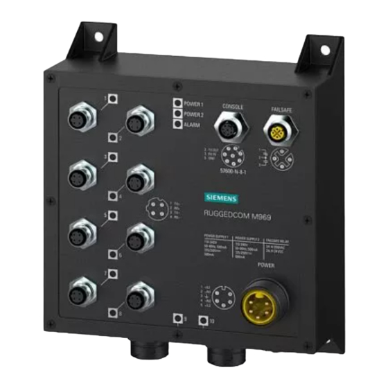
Introduction 1.2 Description Universal Power Supply Options • Fully integrated power supply • Universal high-voltage range: 88-300 VDC or 85-264 VAC. • Popular low-voltage DC ranges: 12, 24, 48 VDC • Dual redundant, parallel load-sharing power supplies (option) • Can be powered from different sources for ultimate redundancy •... - Page 12 Introduction 1.2 Description Copper Ethernet Ports Port Status LED POWER 1 LED POWER 2 LED ALARM LED RS-232 Console Port Failsafe Output Relay M12 Power Supply Port Fiber Optic Ethernet Ports RUGGEDCOM M969F Installation Manual, 11/2022, C79000-G8976-1349-04...
- Page 13 Introduction 1.2 Description Surge Ground Connection Chassis Ground Connection Figure 1.1 RUGGEDCOM M969F (M12 Connectors Shown) Copper Ethernet Ports Port Status LED POWER 1 LED RUGGEDCOM M969F Installation Manual, 11/2022, C79000-G8976-1349-04...
-
Page 14: Required Tools And Materials
Introduction 1.3 Required Tools and Materials POWER 2 LED ALARM LED RS-232 Console Port Failsafe Output Relay M23 Power Supply Port Fiber Optic Ethernet Ports Surge Ground Connection Chassis Ground Connection Figure 1.2 RUGGEDCOM M969F (RJ45 Connectors Shown) Port Status LED Indicate the status of each port. State Description Yellow (Solid) -
Page 15: Decommissioning And Disposal
Siemens recommends using RUGGEDCOM industrial Ethernet shielded cables for all Ethernet ports. Siemens does not recommend the use of copper cabling of any length for critical, real-time substation automation applications. All copper Ethernet ports on RUGGEDCOM products include transient suppression circuitry to protect against damage from electrical transients and conform with IEC 61850-3 and IEEE 1613 Class 1 standards. -
Page 16: Tamper-Evident Security Seals
NOTICE Worn, damaged or missing seals must be replaced immediately. Replacement seals are available for purchase from Siemens. For more information, contact a Siemens Sales representative. There are three ways to determine if a security seal has been tampered with: •... - Page 17 Introduction 1.7 Ingress Protection Figure 1.3 Caps RUGGEDCOM M969F Installation Manual, 11/2022, C79000-G8976-1349-04...
-
Page 18: Installing The Device
This product contains no user-serviceable parts. Attempted service by unauthorized personnel shall render all warranties null and void. Changes or modifications not expressly approved by Siemens Canada Ltd. could invalidate specifications, test results, and agency approvals, and void the user's authority to operate the equipment. -
Page 19: General Procedure
Visually inspect each item in the package for any physical damage. Verify all items are included. Note If any item is missing or damaged, contact Siemens for assistance. Mounting the Device The RUGGEDCOM M969F is designed to be mounted on a panel by affixing the top and bottom flanges of the device to a panel using screws. -
Page 20: Connecting The Failsafe Alarm Relay
Installing the Device 2.4 Connecting the Failsafe Alarm Relay Note For detailed dimensions of the device with panel mount hardware installed, refer to "Dimension Drawings" (Page 25). To mount the device to a panel, do the following: Place the device against the panel and align the flanges with the mounting holes. -
Page 21: Connecting Power
Installing the Device 2.5 Connecting Power The proper relay connections are as follows: Description Normally Closed Common Normally Open Figure 2.2 Failsafe Alarm Relay Wiring Connecting Power The M23 power connector has five terminal pins, which means two power supply sources are allowed to power the RUGGEDCOM M969F with the M23 power connector. -
Page 22: 2.5.2 Power Supply Wiring
Installing the Device 2.5.2 Power Supply Wiring Terminal # Description Usage bus for DC inputs. This terminal is connected to chassis ground internally. An additional chassis ground screw is also present that connects chassis ground to both power supply surge grounds via a removable jumper. - Page 23 Installing the Device 2.5.2 Power Supply Wiring Neutral Safety Line 250 VAC Breaker 110/230 VAC Power Source Safety Earth Figure 2.4 AC Power Supply Wiring Example (M23 Power Connector) Single Low DC Power Supply Wiring M23 Power Connector Ground Bus 300 VDC Breaker DC Power Source Figure 2.5 DC Power Supply Wiring Example (M23 Connector)
- Page 24 Installing the Device 2.5.2 Power Supply Wiring 250 VAC Breaker Neutral 110/230 VAC Power Source (PS2) 110/230 VAC Power Source (PS1) Safety Figure 2.6 AC and AC Power Supply Wiring Example M23 Power Connector Ground Bus Line 250 VAC Breaker 110/230 VAC Power Source (PS2) Neutral Safety 300 VDC Breaker...
-
Page 25: 2.5.3 Disabling Line-To-Ground Transient Protection
Installing the Device 2.5.3 Disabling Line-to-Ground Transient Protection Ground Bus 300 VDC Breaker DC Power Source (PS2) DC Power Source (PS1) Figure 2.8 DC and DC Power Supply Wiring Example 2.5.3 Disabling Line-to-Ground Transient Protection All line-to-ground transient energy is shunted to the Surge Ground terminal. In cases where users require the inputs to be isolated from ground, remove the ground braid between Surge and Chassis Ground. -
Page 26: Device Management
Device Management This section describes how to connect to and manage the device. Connecting to the Device The following describes the various methods for accessing the RUGGEDCOM M969F console and Web interfaces on the device. For more detailed instructions, refer to the "RUGGEDCOM M969F Configuration Manual"... -
Page 27: Configuring The Device
Device Management 3.2 Configuring the Device device's IP address. The factory default IP address for the RUGGEDCOM M969F is https://192.168.0.1. For more information about available ports, refer to "Communication Ports" (Page 19). Configuring the Device Once the device is installed and connected to the network, it must be configured. All configuration management is done via the RUGGEDCOM M969F interface. -
Page 28: Communication Ports
Communication Ports The RUGGEDCOM M969F can be equipped with various types of communication ports to enhance its abilities and performance. To determine which ports are equipped on the device, refer to the factory data file available through RUGGEDCOM M969F. For more information on how to access the factory data file, refer to the "RUGGEDCOM M969F User Guide"... -
Page 29: Copper Ethernet Ports
Communication Ports 4.1 Copper Ethernet Ports RJ45 Copper Ethernet Ports Fiber Optic Ethernet Ports Figure 4.2 Port Assignment (RJ45 Connectors Shown) Copper Ethernet Ports The RUGGEDCOM M969F supports eight 10/100Base-TX Ethernet ports that allow connection to standard Category 5 (CAT-5) unshielded twisted-pair (UTP) cables with RJ45 male connectors or M12 male connectors. -
Page 30: Fiber Optic Ethernet Ports
Communication Ports 4.2 Fiber Optic Ethernet Ports cause excessive noise and interference, but more importantly, create a potential shock hazard that can result in serious injury. Pin-Out (RJ45) The following is the pin-out description for the RJ45 connectors: 10/100Base- Description TX Signal Receive Data+ Receive Data-... - Page 31 Communication Ports 4.2 Fiber Optic Ethernet Ports Tx Connector Rx Connector Figure 4.5 LC Port For specifications on the available fiber optic Ethernet ports, refer to "Fiber Optic Ethernet Port Specifications" (Page 24). RUGGEDCOM M969F Installation Manual, 11/2022, C79000-G8976-1349-04...
-
Page 32: Technical Specifications
Technical Specifications This section details the specifications and operating conditions of the device. Power Supply Specifications Power Minimum Maximum Internal Isolation Maximum Supply Type Input Input Fuse Rating Power Consumption 12–24 VDC 10 VDC 36 VDC 3.15A (T) 1.5 kVDC 10 W 24 VDC 18 VDC... -
Page 33: Fiber Optic Ethernet Port Specifications
All cabling is duplex type unless otherwise specified. • Maximum segment length is greatly dependent on factors such as fiber quality, and the number of patches and splices. Consult a Siemens sales associate when determining maximum segment distances. • All optical power numbers are listed as dBm averages. To convert from average to peak, add 3 dBm. -
Page 34: Mechanical Specifications
Technical Specifications 5.6 Mechanical Specifications Ambient Storage -40 to 85° C (-40 to 185° F) Temperature Ambient Relative 5% to 95% Humidity Maximum Altitude 15240 m (50000 ft) Measured from a 30 cm (12 in) radius surrounding the center of the RUGGEDCOM M969F enclosure. Reduced to -40 to 80 °C (-40 to 76 °F) when equipped with a 100Base-FX, single-mode, 1300 nm, long-reach 90 km port(s). - Page 35 Technical Specifications 5.7 Dimension Drawings Figure 5.1 8 RJ45 IP67 Ethernet Ports and M23 Power RUGGEDCOM M969F Installation Manual, 11/2022, C79000-G8976-1349-04...
- Page 36 Technical Specifications 5.7 Dimension Drawings Figure 5.2 8 M12 D-Code Ethernet Ports and M23 Power RUGGEDCOM M969F Installation Manual, 11/2022, C79000-G8976-1349-04...
- Page 37 Technical Specifications 5.7 Dimension Drawings RUGGEDCOM M969F Installation Manual, 11/2022, C79000-G8976-1349-04...
-
Page 38: Accessories
Accessories This chapter details the various accessories available for the RUGGEDCOM M969F. Power (1/unit) M23 Power Mating Connector • Description M23 5pin female connector, 600V, IP68 rated • Order Code 99-60-0007 Cable Specifications • 3/18 AWG, jacket OD range 0.20" - 0.48"... -
Page 39: Console (1/Unit)
Accessories 6.2 Console (1/unit) Figure 6.2 M23 Power Cable Console (1/unit) M12 Console Port Mating Cable • Description M12 8pin A-code male to DB9 female; unshielded, PUR jacket cable, 30V/4A, • Order Code 99-43-0023-001 Cable Specifications • M12 8pin A-code male to free end, Figure 6.3 M12 Console Port Mating Cable M12 Console Port Mating Connector... -
Page 40: Failsafe (1/Unit)
Accessories 6.3 Failsafe (1/unit) Figure 6.4 M12 Console Port Mating Connector Failsafe (1/unit) M12 FailSafe Port Mating Cable Description • M12 4pole A-coded; unshielded, PUR Jacket cable, 3m • Order Code 99-43-0024-001 Figure 6.5 M12 FailSafe Port Mating Cable M12 FailSafe Port Mating Connector Description •... -
Page 41: Ethernet (8/Unit)
Accessories 6.4 Ethernet (8/unit) Figure 6.6 M12 FailSafe Port Mating Connector Ethernet (8/unit) M12 D-code Ethernet Port Mating Cable • Description M12 D-code to RJ45; patch cable, 3meters • Order Code 99-43-0040-001 • Cable Specifications M12 D-code male 4 pin, CAT5e, 3m Figure 6.7 M12 D-code Ethernet Port Mating Cable... - Page 42 Accessories 6.4 Ethernet (8/unit) Figure 6.8 M12 D-code Ethernet Port Mating Connector M12 D-Code Ethernet Port Mating Cable • Description M12 male D-code to male D-code; shielded PUR jacket patch cable, 5 meters • Order Code 99-43-0041-001 Cable Specifications • M12 male 4 pin, CAT 5e, 5m Figure 6.9 M12 D-Code Ethernet Port Mating Cable...
- Page 43 Accessories 6.4 Ethernet (8/unit) • Description IP67 Metal RJ45 plug on both ends; Category 5e shielded patch cable, 3m • Order Code 99-43-0039-001 Figure 6.11 IP67 Metal RJ45 Ethernet Port Mating Cable IP67 Metal RJ45 Ethernet Port Mating Connector Description • IP67 Metal RJ45 plug, field attachable •...
-
Page 44: Lc Fiber Optic (2/Unit)
Accessories 6.5 LC Fiber Optic (2/unit) LC Fiber Optic (2/unit) LC Port Mating Connector Description • Cable Multimode Metal IP67LC to LC, Multimode fiber cable 3meters, IP67 rated • Order Code 99-43-0057-001 Figure 6.14 LC Port Mating Connector • Description Cable Singlemode Metal IP67 LC to LC, Singlemode fiber cable 3 meters, IP67 rated Order Code... - Page 45 Accessories 6.5 LC Fiber Optic (2/unit) Figure 6.16 LC Port Mating Connector • Description Cable Singlemode Metal IP67 LC to Metal IP67 LC, Singlemode fiber cable 3 meters, IP67 rated Order Code • 99-43-0053-001 Figure 6.17 LC Port Mating Connector LC Port Mating Connector •...
- Page 46 Accessories 6.5 LC Fiber Optic (2/unit) LC, RJ45 Port Cap • Description RJ45 outlet cap IP67, Metal • Order Code 99-60-0011 Figure 6.20 LC, RJ45 Port Cap RUGGEDCOM M969F Installation Manual, 11/2022, C79000-G8976-1349-04...
- Page 47 Accessories 6.5 LC Fiber Optic (2/unit) RUGGEDCOM M969F Installation Manual, 11/2022, C79000-G8976-1349-04...
-
Page 48: Certification
Approvals This section details the standards to which the RUGGEDCOM M969F complies. Note All relevant certificates and test reports are available on Siemens Industry Online Support [https://support.industry.siemens.com]. 7.1.1 UKCA This device is certified for use in Great Britain and bears the United Kingdom Certified Assessed (UKCA) marking. -
Page 49: European Union (Eu)
Certification 7.1.3 European Union (EU) 7.1.3 European Union (EU) This device is declared by Siemens Canada Ltd. to comply with essential requirements and other relevant provisions of the following EU directives: • EN 62368-1 Information Technology Equipment – Safety – Part 1: General Requirements •... -
Page 50: Fda/Cdrh
Title 21 Code of Federal Regulations (CFR) – Chapter I – Sub-chapter J – Radiological Health 7.1.6 ISED This device is declared by Siemens Canada Ltd. to meet the requirements of the following ISED (Innovation Science and Economic Development Canada) standard: • CAN ICES-3 (A)/NMB-3 (A) This device further complies with IC RSS-210 and is approved under the ID 4997A- VG5RW80G. -
Page 51: Mil-Std Test Specifications
Certification 7.2 MIL-STD Test Specifications • IEC 61000-6-2 Electromagnetic Compatibility (EMC) – Part 6-2: Generic Standards – Immunity for Industrial Environments IEC 61850-3 • Communication Networks and Systems in Substations – Part 3: General Requirements NEMA TS-2 • Traffic Controller Assemblies with NTCIP Requirements •... -
Page 52: Emc And Environmental Type Tests
Certification 7.3 EMC and Environmental Type Tests Test Description MIL-STD 901D High Impact Shock Test MIL-STD-1275B Power Quality MIL-STD-1399 DC Magnetic Field Testing Section 070 Part 1 EMC and Environmental Type Tests The RUGGEDCOM M969F has passed the following EMC and environmental tests. IEC 61850-3 Type Tests Test Description... - Page 53 Certification 7.3 EMC and Environmental Type Tests Test Description Test Levels Severity Levels AC Power ports 2.5 kV common, 1 kV differential mode @ 1MHz IEC 61000-4-16 Mains Frequency Signal ports 30 V Continuous, 300 V for 1 s Voltage DC Power ports 30 V Continuous, 300 V for 1 s IEC 61000-4-17 Ripple on DC...
- Page 54 Certification 7.3 EMC and Environmental Type Tests Environmental Type Tests Note Class 2 refers to Measuring relays and protection equipment for which a very high security margin is required or where the vibration levels are very high, (e.g. shipboard application and for severe transportation conditions). Test Description Test Levels...
- Page 55 Certification 7.3 EMC and Environmental Type Tests RUGGEDCOM M969F Installation Manual, 11/2022, C79000-G8976-1349-04...
- Page 56 For more information Siemens RUGGEDCOM https://www.siemens.com/ruggedcom Industry Online Support (service and support) https://support.industry.siemens.com Industry Mall https://mall.industry.siemens.com Siemens Canada Ltd. Digital Industries Process Automation 300 Applewood Crescent Concord, Ontario, L4K 4E5 Canada © 2022 Siemens Canada Ltd. Subject to change...