Table of Contents
Advertisement
Quick Links
Advertisement
Table of Contents

Related Manuals for ABB Nitrate 8236


Summary of Contents for ABB Nitrate 8236
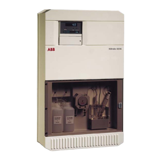
- Page 1 Instruction Manual ISE Nitrate Monitor IM/8236_8 8236...
- Page 2 Cert. No. Q 05907 As a part of ABB, a world leader in process automation technology, we offer customers application expertise, service and support worldwide. EN 29001 (ISO 9001) We are committed to teamwork, high quality manufacturing, advanced technology and unrivalled service and support.
-
Page 3: Table Of Contents
CONTENTS Section Page Section Page 1 INTRODUCTION .............. 2 7 CALIBRATION ............... 29 1.1 Description ............... 2 7.1 Calibration Sequence ..........29 1.2 Training ..............2 8 MAINTENANCE ............. 30 1.3 Location and Function of Main Components ... 2 8.1 Chemistry ............... 30 2 INSTALLATION .............. -
Page 4: Introduction
The Model 8236 Nitrate Monitor is a microprocessor based presented to a multi-channel peristaltic pump which proportions analyser using an ABB nitrate ion-selective probe. This sample and reagent solutions through the monitor to the mixing equipment is used for environmental water monitoring. -
Page 5: Installation
2 INSTALLATION 2.1 Accessories Mains and signal cables are connected through cable glands in 1 x reagent bottle 1 x nitrate refurbishing kit the User Junction Box on the right hand side with the exception of 4 x calibration bottles 1 x double junction the optional serial interface which connects directly into the 1 x nitrate inner electrode... -
Page 6: Connections, General
…2 INSTALLATION 2.6 Connections, General Warnings. • A disconnecting device such as a switch or circuit breaker conforming to local safety standards must be fitted to the final installation. It must be fitted in close proximity to the instrument within easy reach of the operator and must be marked clearly as the disconnection device for the instrument. -
Page 7: External Electrical Connections
2 INSTALLATION… 2.7 External Electrical Connections – Fig. 2.3 The connections are as follows: The external electrical connections are to be found in the User Junction Box with the exception of the optional serial interface a) Mains input 115 V or 240 V. The mains voltage is selected by which is connected directly into the Microprocessor Unit. -
Page 8: Relay Contact Protection And Interference Suppression
…2 INSTALLATION 2.8 Relay Contact Protection and Interference as shown in Fig. 2.5A. If the instrument malfunctions the value of Suppression – Fig. 2.5 the RC network is too low for suppression and an alternative If the relays are used to switch loads on or off the relay contacts value must be used. -
Page 9: Setting Up
3 SETTING UP 2 INSTALLATION Note. Before proceeding any further, ensure that all switches are set to OFF on the right hand side of the electronics unit – see Fig. 2.3. a) Ensure that all external electrical and plumbing connections have been made correctly. -
Page 10: Liquid Handling Section
4 LIQUID HANDLING SECTION 4 LIQUID HANDLING SECTION… 4.1 Principle of Operation – Figs. 4.1 The monitor uses a Nitrate Ion–Selective Electrode in conjunction with a double junction Reference Electrode. The Nitrate Electrode is a liquid membrane type sensor employing an ion–exchange liquid in contact with the sample via a porous membrane. -
Page 11: General Operation
5 ELECTRONICS SECTION …4 LIQUID HANDLING SECTION 4.2 General Operation – Fig. 4.2 5.1 Electronic Layout – Fig. 5.1 The sequence of events is: The electronic section comprises two separate sections: a) The sample enters the constant head unit from below and any excess is allowed to overflow to drain. -
Page 12: Front Panel Controls
…5 ELECTRONICS SECTION 5.4 Front Panel Controls – Fig. 5.2 The programme controls comprise eight tactile membrane 20-character Alarm and Status 5-digit Display switches. These switches are situated behind a hinged door Dot-Matrix Display L.E.D.s (Concentration) below the display, access is via a screwdriver-operated catch. In normal operation the switches are used to view the measured ion concentration value, initiate a manual calibration, or to activate the 'alarm hold' facility. -
Page 13: Programming
6 PROGRAMMING... -
Page 14: Normal Operation
…6 PROGRAMMING 6.1 Normal Operation 6.2 Programming Pages In normal operation (Operating Page 1) the lower, dot matrix, Operation of the switch enables a series of 'programming' display gives indication of the units of measurement, millivolt pages to be displayed. Unauthorised entries to this page are value, sensor slope and time. -
Page 15: Operating
6 PROGRAMMING… 6.2.1 Operating Page 1 The values displayed in Operating Page 1 are for viewing only and cannot be altered in this page. Measurement Units Nitrate <Unit> The measurement units are displayed, e.g. Nitrate ppm. Advance to next parameter. Mode Sensor Output •... -
Page 16: Operating
…6 PROGRAMMING 6.2.2 Operating Page 2 To gain access to the Calibration Page (Operating Page 2), operate the switch. Enable Automatic Calibrations Enable Auto Cals Yes Select ‘Yes’ to enable or ‘No’ to disable the automatic calibrations. Enter Store. Advance to next parameter. MANUAL CAL SEQUENCE Page header. -
Page 17: Security Code Page
6 PROGRAMMING… …6.2.2 Operating Page 2 Continued from previous page. Calibrating Std 2 Calibrating Standard 2 The upper display shows the nitrate concentration value. The display remains until a stable output is obtained from the probe. Toggle between the two displays. –... -
Page 18: Set Up Input Page
…6 PROGRAMMING 6.2.4 Set Up Input Page Page header. SET UP INPUT Advance to next parameter. C Control Temperature Control Temp – – – • Set the required block control temperature within the range 5 to 45 °C in 0.1 °C increments. -
Page 19: Current Output Page
6 PROGRAMMING… 6.2.5 Current Output Page The current output is assigned to the nitrate concentration but is only operative if the relevant output modules are fitted – see Fig. 2.4. CURRENT OUTPUT Page header. Advance to next parameter. OP1 Cal Hold Output 1 Calibration Hold Current Output 1 can be held during calibration, if required. - Page 20 …6 PROGRAMMING …6.2.5 Current Output Page Continued from previous page. Output 2 Calibration Hold OP2 Cal Hold Current Output 2 can be held during calibration, if required. Select ‘YES’ or ‘NO’. Store. Enter Advance to next parameter. Output 2 Law OP2 Law Current Output 2 can be either logarithmic or linear.
- Page 21 6 PROGRAMMING… Continued from previous page. Test Output Zeros Test Current Output Zeros The instrument automatically transmits a current output zero test signal on both outputs. Example – For a 4 to 20 mA current output range, 4 mA is transmitted. Advance to next parameter.
-
Page 22: Set Up Alarms Page
…6 PROGRAMMING 6.2.6 Set Up Alarms Page Alarm l.e.d. indication and relay output can be assigned either to the nitrate concentration or switched off. SET UP ALARMS Page header. Advance to next parameter. A1 Enabled Alarm A1 Enable Select ‘YES’ to enable or ‘NO’ to disable. Store. - Page 23 6 PROGRAMMING… Continued from Previous page. – – – – A1 Setpoint • A1 Setpoint Set the required setpoint value. Enter Store. Advance to next parameter. A2 Enabled A2 Enabled Repeat the programming procedures as for Alarm Relay 1. A2 Setpoint –...
-
Page 24: Set Up Clock Page
…6 PROGRAMMING 6.2.7 Set Up Clock Page SET UP CLOCK Page header. Advance to next parameter. Set Up Real Time Clock Select ‘Yes’ to set up the clock, otherwise select ‘No’. Set Clock? Store. Enter Advance to next parameter. Set Year –... - Page 25 6 PROGRAMMING… Continued from previous page. – – Set Minutes Set Minutes Set the appropriate minutes. Enter Store. Advance to next parameter. – – Set Seconds Set Seconds Set the appropriate seconds. Enter Store. Advance to next parameter. Flashing Cal Date DD:MM:YY Calibration Date (day of the month) Set the day of the month when the first automatic calibration is to be carried out.
-
Page 26: Calibration User Code Page
…6 PROGRAMMING …Set Up Clock Page Continued from previous page. Flashing Cal Time HH:MM Calibration Time (hour – 24 hour clock) Set the hour of the day when the first automatic calibration is to be carried out. Enter Flashing Store and advance to next parameter. Cal Time HH:MM Calibration Time (minutes) -
Page 27: Set Up Temperature Control Page
6 PROGRAMMING… 6.2.9 Set Up Temperature Control Page The parameters within this page are factory preset and should not require any adjustment. SET UP TEMP. CONTROL Page header. Advance to next parameter. Cycle Time Cycle Time The cycle time is adjustable between 5 and 60 seconds in 1 second increments. Advance to next parameter. -
Page 28: Electrical Calibration Page
…6 PROGRAMMING 6.2.11 Electrical Calibration Page Page header. CALIBRATION Advance to next parameter. Millivolt Input Zero mV Zero – – – – Set the millivolt source to –400 mV. Set the display to ‘–400’ mV. Store. New value is accepted only when input is stable. Enter Advance to next parameter. - Page 29 6 PROGRAMMING… Continued from previous page. Adjust Current Output 1 Zero Adjust Output 1 Zero The monitor transmits a zero signal, e.g. for a 4 to 20 mA output range, 4 mA is transmitted. Set the milliammeter reading to the current output 1 zero level, i.e. 0 mA (zero-based ranges) or 4 mA (4 to 20 mA range).
- Page 30 …6 PROGRAMMING …Electrical Calibration Page Continued from previous page. Cal Time 1 10 m Calibration Time 1 The displayed value is preset at the factory and must not be altered. See Table 7.1. Advance to next parameter. Cal Time 2 10 m Calibration Time 2 The displayed value is preset at the factory and must not be altered.
-
Page 31: Calibration
7 CALIBRATION 7.1 Calibration Sequence sequentially to shut off the sample and admit standard solutions of known concentration, one low and one high (STD1 and STD2), Calibration of the monitor is carried out by replacing the sample solution sequentially with two standard solutions of known to the sample path. -
Page 32: Maintenance
50 to 80 ml of each standard solution each calibration cycle; consumption of the standard solution, also Note. Bottles of solution are available from ABB – see depends on the frequency with which this cycle is carried out. -
Page 33: Four Monthly
ABB Instrumentation Ultrafilters, if used. If severe, this e) Repeat the process using high purity water to flush out the growth may cause blockages in tubing or valves and/or fouling of sodium hypochlorite solution. -
Page 34: Consumables Spares Kit
…8 MAINTENANCE 8.2.6 Consumables Spares Kit i) Take a washer from the spares pack in the kit and place it over the membrane, carefully centralising it in the end cap. If one is not supplied, it should be ordered before the end of the first year of operation. -
Page 35: Peristaltic Pump
8 MAINTENANCE… 8.2.9 Replacement of Plumbing Tubing c) Remove the teat from the reference electrode and the stopper from the refill aperture. Top up with salt bridge solution if All necessary items are included in the Consumable Spares Kit. required. a) Remove sensors for short term storage. -
Page 36: Shutdown Procedure
…8 MAINTENANCE 8.3 Shutdown Procedure b) Hold the electrode body over a small beaker of methanol; 8.3.1 Short Term unscrew the end cap and allow the end cap assembly and The nitrate ion–selective electrode may be stored dry or ion–exchanger solution to fall into the methanol. immersed in a dilute nitrate solution, e.g. -
Page 37: Monitor Diagnostic Information
8 MAINTENANCE… Mechanical components which are involved with the liquid e) Check that the fill hole stopper has been moved away from handling, for example, pumps, valves, tubing and tubing the salt bridge filling solution hole in the reference electrode. connections etc., should be systematically checked for correct operation, and for leaks or blockages which change the chemical f) Refurbish nitrate electrode –... -
Page 38: Microprocessor Unit Error Messages
…8 MAINTENANCE 8.6 Microprocessor Unit Error Messages The instrument incorporates an automatic self-diagnostic checking facility for detection of input and output errors. If such a fault occurs, one of the error messages detailed below is shown on the dot matrix display. ‘CHAN 1 INPUT ERROR’... -
Page 39: Specification
9 SPECIFICATION Range Calibration Nitrate Any two consecutive decades of concentration Fully automatic two-point, plus manual initiation on demand –1 between 0.2 and 1000mgl Routine maintenance –1 – as N, or 1.0 and 5000mgl as NO Four-weekly: replenish reagents, clean flow system Repeatability Twelve-monthly: replace plumbing, pump tubing and pump... -
Page 40: Spares List
10 SPARES LIST Consumable Spares t i k t i k Refurbishment Spares t i k c i l – v l i l i o – – – l n i – – l l e l l e r r i ' t r , y l... - Page 41 …10 SPARES LIST …Strategic Spares l a i s i l l a i s i l l a i – – – c t i l a i Fuses (Junction Box) – - i t – – - i t Fuse (Transmitter Power Supply Board 4500/0817) –...
-
Page 42: Appendix A - Replacing Software Eprom
APPENDIX A – REPLACING SOFTWARE EPROM A.2 Access the PCB – Fig. A.2 Warning. Switch off the monitor and electrically isolate it before carrying out the following steps. Unlock and open cover plate and A.1 Access the Transmitter Unit – Fig. A.1 hinge out to expose captive screws. -
Page 43: Removing The Pcb
APPENDIX A A.3 Removing the PCB – Fig. A.3 Remove the four screws attaching the PCB to the assembly. Note that there are washers between the PCB cover and the PCB. Withdraw the PCB and turn it over to reveal the component side. Locate and change the EPROM IC1 –... -
Page 44: Notes
NOTES... - Page 45 NOTES…...
- Page 46 …NOTES...
- Page 47 – Manufacturing United Kingdom – Metals and Minerals – Oil, Gas & Petrochemical ABB Limited – Pulp and Paper Tel: +44 (0)1453 826661 Fax: +44 (0)1453 829671 Drives and Motors United States of America • AC and DC Drives, AC and DC Machines, AC motors to 1kV ABB Inc.
- Page 48 ABB has Sales & Customer Support The Company’s policy is one of continuous product improvement and the right is reserved to modify the expertise in over 100 countries worldwide information contained herein without notice. Printed in UK (07.05) www.abb.com © ABB 2005 ABB Limited ABB Inc.