Advertisement
Quick Links
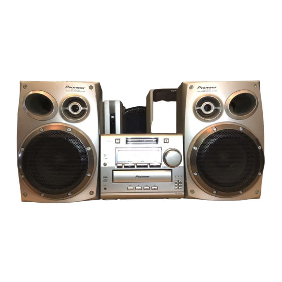
SPEAKER SYSTEM
S-A550
This product is component of system.
For the operating instructions, refer to the service manual RRV2006 for XR-A550.
FOR PRECAUTION OF
REASSEMBLY AND DISASSEMBLY
The cosmetic baffle assy is attached to the cabinet by 4 external
screws. To detach the cosmetic baffle assy, loosen these
screws. Then carefully disconnect the wires of the woofer and
mid-range mounted on the cosmetic baffle assy. To attach the
cosmetic baffle assy, replace it on the cabinet correctly and se-
cure with 4 screws.
The woofer is attached to the cosmetic baffle assy together with
the woofer ring assy by 4 internal screws. To detach the woofer
(woofer ring assy), loosen these screws. To attach the woofer
ring assy, fit the boss of the woofer ring to the hole of the cos-
metic baffle assy. To attach the woofer, face its terminal down-
ward, and fit the portion of the notch and hole of the frame to
the bank and hole of the cosmetic baffle assy. To attach the
woofer ring assy and woofer, replace it on the cosmetic baffle
assy correctly and secure with 4 screws.
The mid-range is attached to the cosmetic baffle assy by 2 inter-
nal screws. To detach the mid-range, loosen these screws. Then
carefully disconnect the wires of the tweeter mounted on the
cosmetic baffle assy by adhesion. To attach the mid-range, re-
place it on the cosmetic baffle assy correctly and secure with 2
screws.
PIONEER ELECTRONIC CORPORATION
PIONEER ELECTRONICS SERVICE, INC. P.O. Box 1760, Long Beach, CA 90801-1760, U.S.A.
PIONEER ELECTRONIC (EUROPE) N.V. Haven 1087, Keetberglaan 1, 9120 Melsele, Belgium
PIONEER ELECTRONICS ASIACENTRE PTE. LTD. 501 Orchard Road, #10-00 Wheelock Place, Singapore 238880
PIONEER ELECTRONIC CORPORATION 1998
XJI/E
The network assy is attached to the back board of the cabinet by
press-fitting. To detach the network assy, strike the cord-stop-
per of the network assy with a hammer from inside of the cabi-
net. To attach the network assy, replace it on the back board of
the cabinet correctly by press-fitting.
When exchange the tweeter, do it with the cosmetic baffle assy.
4-1, Meguro 1-Chome, Meguro-ku, Tokyo 153-8654, Japan
ORDER NO.
RRV2000
T-ZZW AUG. 1998 Printed in Japan
Advertisement

Related Manuals for Pioneer S-A550 XJI/E


Summary of Contents for Pioneer S-A550 XJI/E
- Page 1 PIONEER ELECTRONICS SERVICE, INC. P.O. Box 1760, Long Beach, CA 90801-1760, U.S.A. PIONEER ELECTRONIC (EUROPE) N.V. Haven 1087, Keetberglaan 1, 9120 Melsele, Belgium PIONEER ELECTRONICS ASIACENTRE PTE. LTD. 501 Orchard Road, #10-00 Wheelock Place, Singapore 238880 PIONEER ELECTRONIC CORPORATION 1998...
- Page 2 S-A550 PARTS LIST NOTES: Parts marked by "NSP" are generally unavailable because they are not in our Master Spare Parts List. mark found on some component parts indicates the importance of the safety factor of the part. Therefore, when replacing, be sure to use parts of identical designation. Mark No.