
Related Manuals for Toshiba BMS-CT2560U-E


Summary of Contents for Toshiba BMS-CT2560U-E
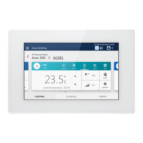
- Page 1 Central Control Device (Touch Screen Controller) Installation Manual For commercial use Model name: BMS-CT2560U-E (BMS-CT1280TU) (BMS-CT2560U-TR) • Save These Instructions! ENGLISH...
-
Page 2: Table Of Contents
Central Control Device (Touch Screen Controller) Installation Manual •Thank you for purchasing the system controller. •Please read this installation manual carefully before installation, and perform the work only in the correct manner. Contents 1 Precautions for safety ..........3 2 Specifications . -
Page 3: Precautions For Safety
Central Control Device (Touch Screen Controller) Installation Manual Precautions for safety • Read these “Precautions for safety” carefully before installation. • The precautions described below include important items regarding safety. Observe them without fail. Understand the following details (indications and symbols) before reading the body text, and follow the instructions. •... - Page 4 Central Control Device (Touch Screen Controller) Installation Manual CAUTION • Do not install in the following locations: Locations where combustible gas may leak Locations with high humidity or water Dusty locations Locations in direct sunlight and locations subject to high temperatures Locations within 1 m from televisions or radios Outdoors, under awnings, or other locations exposed to rain and dew Locations exposed to outside air containing corrosive gases or salinity...
-
Page 5: Specifications
Central Control Device (Touch Screen Controller) Installation Manual Specifications Product name Touch Screen Controller Model Name BMS-CT2560U-E, BMS-CT2560U-TR Power supply 220-240 V AC* 50/60 Hz Consumed current 1.17 A Up to 256 units Indoor unit (LINK1 terminal: maximum 128 units, LINK2 terminal: maximum 128 units) - Page 6 Central Control Device (Touch Screen Controller) Installation Manual Power adapter 110.0±0.5 1500.0±20.0 31.5 FERRITE AS REQUIRED 33.0±0.5 30±5 29.6±0.5 WIRE NO:1185 +0.15 -0.0 GAUGE:16AWG (BLACK) Ø12.0±0.5 SPEC LABEL Ø5.5±0.1 Ø2.5 +0.1 Component Names OUTPUT Terminal block for INPUT external contact output INPUT LINK1 (Uh) LINK2 (Uh)
- Page 7 Central Control Device (Touch Screen Controller) Installation Manual Before Installation Confirm that all the parts listed below are included in the package. Included Items Component name Quantity Remarks System Controller Power adapter Owner’s Manual Installation Manual Fixing screw Fixing screw (M4×12) for attaching the main unit from the front Fixing screw Fixing screw (M3×8) for attaching the main unit from the rear Closed end connector...
-
Page 8: Installation
Central Control Device (Touch Screen Controller) Installation Manual Installation CAUTION • Do not wire communication lines or input/output wiring next to power supply wiring, etc., or house them in the same metal pipe. Doing so may result in failure. • Install the main unit away from noise sources. 3-1. -
Page 9: When Installing From The Rear
Central Control Device (Touch Screen Controller) Installation Manual 3-1-2. When Installing from the Rear Main unit box Panel System controller to wall, etc. fixing hole dimensions Hole dimensions to drill in wall 190.4 4-Ø4.5 round hole 4-M3 nut * Although the panel and the main unit box are separated to explain the screw attachment part in an easy to understand manner, it is not necessary to remove the main unit box from the panel in actual installation work. -
Page 10: Attaching The Power Adapter
Central Control Device (Touch Screen Controller) Installation Manual 3-2. Attaching the Power Adapter The power adapter can be installed on a flat surface or on a wall. Do not install it in any other orientation. Fix with the attached binding band and double-sided tape. Installation not allowed Installation allowed * Install so that the power cable that connects... -
Page 11: Power, Signal, And Earth Line Connections
Central Control Device (Touch Screen Controller) Installation Manual 3-3. Power, Signal, and Earth Line Connections Connect the power, signal and earth lines to the specified terminal blocks. REQUIREMENT Attach round crimp terminals to all LINK 1, LINK 2, and RS-485 wiring, and tighten the screws securely. After tightening, check that the wiring cannot come out. - Page 12 Central Control Device (Touch Screen Controller) Installation Manual TU2C-LINK communication line stripping RS-485 cable wire stripping length Digital I/O cable stripping length length Attach a round crimp terminal to each wire of the power line and Loosen the screws with a screwdriver, insert the digital I/O cable, signal line.
- Page 13 Central Control Device (Touch Screen Controller) Installation Manual Design of Control Wiring Communication method and model name The TU2C-LINK model (U series) can be used together with previous models (other than U series). For details of the model and communication method, see the following table. Communication method TU2C-LINK (U series) TCC-LINK (other than U series)
- Page 14 Central Control Device (Touch Screen Controller) Installation Manual When the connected outdoor unit is Super Multi u series (U series) Follow the wiring specifications in the table below even when there is a mix of U series and non-U series in the connected indoor units or remote controllers.
- Page 15 Central Control Device (Touch Screen Controller) Installation Manual When the connected outdoor units are other than Super Multi u series (U series) Wiring specifications Communication line Item Control wiring between indoor and outdoor units and central control wiring 1.25 mm (up to 1000 m) Wire diameter 2.0 mm...
- Page 16 Central Control Device (Touch Screen Controller) Installation Manual When connecting to a previous model light commercial, air to air heat exchanger, air to water heat pump, or general purpose equipment control interface Follow the wiring specifications in the table below even when there is a mix of U series and non-U series in the connected indoor units or remote controllers.
- Page 17 Central Control Device (Touch Screen Controller) Installation Manual Connection to External Devices Example of connection to external equipment which is connected to digital input/output terminal. System controller side External device side Name Item I/O conditions Terminal name Circuit example I/O conditions State Transistor...
- Page 18 Central Control Device (Touch Screen Controller) Installation Manual When using a relay for the circuit on the equipment side of the state output IMPORTANT Be sure to connect freewheeling diodes to both ends of the relay coil. (A relay with a built-in diode is recommended.) (Locally procured) External power supply...
- Page 19 Central Control Device (Touch Screen Controller) Installation Manual Remote monitoring PC LINK2 terminal Central control wiring LAN cable LAN cable (Uh line) Power meter interface RS-485 Control wiring (Uv line) Gr10 Gr16 Group 1 to 16 Digital I/O interface Control wiring (Uv line) Group 17 to 32 Gr17...
- Page 20 DEB5869101-3...