
Related Manuals for Asus BB7002MT


Summary of Contents for Asus BB7002MT
- Page 1 Questo manuale d’istruzione è fornito da trovaprezzi.it. Scopri tutte le offerte per Asus PN61 BB7002MT o cerca il tuo prodotto tra le migliori offerte di PC Desktop e Workstation Mini PC PN61 User Manual...
- Page 2 Copyright © 2018 ASUSTeK COMPUTER INC. All Rights Reserved. LIMITATION OF LIABILITY Circumstances may arise where because of a default on ASUS’ part or other liability, you are entitled to recover damages from ASUS. In each such instance, regardless of the basis on which you are entitled to claim damages from ASUS, ASUS is liable for no more than damages for bodily injury (including death) and damage to real property and tangible personal property;...
-
Page 3: Table Of Contents
Contents About this manual .........................5 Conventions used in this manual ..................6 Typography ..........................6 Package contents ........................7 Getting to know your Mini PC Features .............................10 Front view ..........................10 Left view ...........................12 Right view ..........................13 Rear view ..........................14 Using your Mini PC Getting started ........................18 Connect the AC power adapter to your Mini PC............18 Connect a display panel to your Mini PC ..............20... - Page 4 Appendix Safety information .........................36 Setting up your system .......................36 Care during use ........................36 Regulatory notices ........................38 ASUS contact information ....................43 PN61...
-
Page 5: About This Manual
About this manual This manual provides information about the hardware and software features of your Mini PC, organized through the following chapters: Chapter 1: Getting to know your Mini PC This chapter details the hardware components of your Mini PC. Chapter 2: Using your Mini PC This chapter provides you with information on using your Mini PC. -
Page 6: Conventions Used In This Manual
Conventions used in this manual To highlight key information in this manual, some text are presented as follows: IMPORTANT! This message contains vital information that must be followed to complete a task. NOTE: This message contains additional information and tips that can help complete tasks. -
Page 7: Package Contents
Package contents Your Mini PC package contains the following items: ASUS Mini PC PN Series AC power adapter* Power cord* Technical documentations PN61... - Page 8 For details on these accessories, refer to their respective user manuals. • T he device illustration is for reference only. Actual product specifications may vary with models. • I f the device or its components fail or malfunction during normal and proper use within the warranty period, bring the warranty card to the ASUS Service Center for replacement of the defective components. PN61...
-
Page 9: Getting To Know Your Mini Pc
Getting to know your Mini... -
Page 10: Features
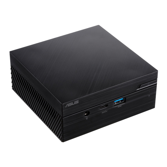
Features Front view Power button The power button allows you to turn the Mini PC on or off. You can use the power button to put your Mini PC to sleep mode or press it for four (4) seconds to force shutdown your Mini PC. Headphone/Headset/Microphone jack This port allows you to connect amplified speakers or headphones. - Page 11 USB 3.1 Gen 1 port The USB 3.1 Gen 1 (Universal Serial Bus) port provides a transfer rate up to 5 Gbit/s. Drive activity indicator This indicator lights up when your Mini PC is accessing the internal storage drive. PN61...
-
Page 12: Left View
Left view Air vents (intake vent) The air vents allow cooler air to enter your Mini PC chassis. IMPORTANT: For an optimum heat dissipation and air ventilation, ensure that the air vents are free from obstructions. PN61... -
Page 13: Right View
Right view Air vents (intake vent) The air vents allow cooler air to enter your Mini PC chassis. IMPORTANT: For an optimum heat dissipation and air ventilation, ensure that the air vents are free from obstructions. Kensington security slot The Kensington security slot allows you to secure your Mini PC using Kensington®... -
Page 14: Rear View
Rear view HDMI port The HDMI (High Definition Multimedia Interface) port supports a Full-HD device such as an LCD TV or monitor to allow viewing on a larger external display. NOTE: This port supports up to HDCP 2.0. Air vents (exhaust vent) The air vents allow your Mini PC chassis to expel hot air out. - Page 15 Configurable port This port varies between models and consists of the following port options: VGA port This port allows you to connect your Mini PC to an external display. Serial (COM) connector The 9-pin serial (COM) connector allows you to connect devices that have serial ports such as mouse, modem, or printers.
- Page 16 USB 3.1 Gen 1 Type-C™/DisplayPort combo port This USB Type-C™ (Universal Serial Bus) port provides a transfer rate of up to 5 Gbit/s, and supports Display port 1.2. Use a USB Type-C™ adapter to connect your Mini PC to an external display. LAN port The 8-pin RJ-45 LAN port supports a standard Ethernet cable for connection to a local network.
-
Page 17: Using Your Mini Pc
Using your Mini PC... -
Page 18: Getting Started
Getting started Connect the AC power adapter to your Mini PC To connect the AC power adapter to your Mini PC: Connect the power cord to the AC power adapter. Connect the DC power connector into your Mini PC’s power (DC) input. - Page 19 IMPORTANT! • W e strongly recommend that you use only the AC power adapter and cable that came with your Mini PC. • W e strongly recommend that you use a grounded wall socket while using your Mini PC. • T he socket outlet must be easily accessible and near your Mini • T o disconnect your Mini PC from its main power supply, unplug your Mini PC from the power socket. NOTE: The power adapter may vary between models and territories, please refer to the following for more information on the different adapters: 90W Power adapter •...
-
Page 20: Connect A Display Panel To Your Mini Pc
Connect a display panel to your Mini PC You can connect a display panel or projector to your Mini PC that has the following connectors: • HDMI connector • VGA connector • DisplayPort • Thunderbolt 3 port NOTE: • U p to two display panels may be connected simultaneously when using the HDMI port and the configurable port*, or HDMI port and USB3.1 Gen 1 Type-C™/DisplayPort combo port. - Page 21 To connect a display panel to your Mini PC: Connect one end of an HDMI, VGA, DisplayPort, or a Thunderbolt 3 cable to an external display, and the other end of the cable to your Mini PC’s HDMI port, VGA port, DisplayPort, or Thunderbolt 3 port. Connect display via VGA port Connect display via HDMI port PN61...
- Page 22 Connect display via Thunderbolt 3 port Connect display via DisplayPort PN61...
-
Page 23: Connect The Usb Cable From Keyboard Or Mouse
Connect the USB cable from keyboard or mouse You can connect generally any USB keyboard and mouse to your Mini PC. You can also connect a USB dongle for a wireless keyboard and mouse set. To connect a keyboard and mouse to your Mini PC: Connect the USB cable from your keyboard and mouse to any of the USB ports of your Mini PC. -
Page 24: Turn On Your Mini Pc
Turn on your Mini PC Press the power button to turn on your Mini PC. PN61... -
Page 25: Turning Your Mini Pc Off
Turning your Mini PC off If your Mini PC is unresponsive, press and hold the power button for at least four (4) seconds until your Mini PC turns off. Putting your Mini PC to sleep To put your Mini PC on Sleep mode, press the Power button once. Entering the BIOS Setup BIOS (Basic Input and Output System) stores system hardware settings that are needed for system startup in the Mini PC. -
Page 26: Load Default Bios Settings
Load default BIOS settings To load the default values for each of the parameters in your BIOS: • Enter the BIOS by pressing <F2> or <DEL> on the POST screen. NOTE: POST (Power-On Self Test) is a series of software controlled diagnostic tests that run when you turn on your Mini PC. •... -
Page 27: Upgrading Your Mini Pc
Upgrading your Mini PC... -
Page 28: Removing The Bottom Cover
IMPORTANT! • I t is recommended that you install or upgrade the memory modules, wireless card, and solid state drive (SSD), under professional supervision. Visit an ASUS service center for further assistance. • E nsure that your hands are dry before proceeding with the rest of the installation process. Before installing any of the features in this guide, use a grounded wrist strap or touch a safely grounded object or metal object to avoid damaging them due to static electricity. -
Page 29: Replacing The Bottom Cover
Replacing the bottom cover Push the bottom cover from the right side towards the left side of the Mini PC (A), then secure it using the four (4) screws removed previously (B). PN61... -
Page 30: Installing Memory Modules
Installing memory modules Your Mini PC comes with two SO-DIMM memory slots that allow you to install two DDR4 SO-DIMMs. IMPORTANT! Refer to http://www.asus.com for the list of compatible DIMMs. You can only install DDR4 SO-DIMMs to the Mini PC’s DIMM slots. -
Page 31: Installing 2.5" Hdd Or Ssd
Installing 2.5” HDD or SSD Prepare your 2.5” HDD or SSD, then align it with the storage bay on the bottom cover of your Mini PC. Insert your HDD or SSD into the storage bay (A), then secure it with four (4) screws (B). -
Page 32: Installing The M.2 Ssd (On Selected Models)
Installing the M.2 SSD (on selected models) Align and insert the 2280 M.2 SSD into its slot inside the Mini PC. Gently push down the 2280 M.2 SSD on top of the screw hole and fasten it using one of the bundled 3mm round screws. PN61... -
Page 33: Installing The Wireless Card
Installing the wireless card NOTE: Your Mini PC includes a M.2 slot for 2230 wireless and Bluetooth modules. Refer to http://www.asus.com for the list of compatible wireless and Bluetooth modules. (optional) Remove the M.2 SSD if an M.2 SSD is installed. To remove the M.2 SSD, remove the screw from the screw hole, then remove the... - Page 34 NOTE: • C onnecting antennas to your wireless card may strengthen the wireless signal. • A soft clicking sound indicates that the antenna has been securely attached on the wireless card. PN61...
-
Page 35: Appendix
Appendix... -
Page 36: Safety Information
Safety information Your Mini PC is designed and tested to meet the latest standards of safety for information technology equipment. However, to ensure your safety, it is important that you read the following safety instructions. Setting up your system • Read and follow all instructions in the documentation before you operate your system. • Do not use this product near water or a heated source. • Set up the system on a stable surface. • Openings on the chassis are for ventilation. Do not block or cover these openings. - Page 37 • If you encounter the following technical problems with the product, unplug the power cord and contact a qualified service technician or your retailer. – The power cord or plug is damaged. – Liquid has been spilled into the system. – The system does not function properly even if you follow the operating instructions. – The system was dropped or the cabinet is damaged. – The system performance changes.
-
Page 38: Regulatory Notices
ASUS REACH website at http://csr.asus.com/ english/REACH.htm ASUS Recycling/Takeback Services ASUS recycling and takeback programs come from our commitment to the highest standards for protecting our environment. We believe in providing solutions for you to be able to responsibly recycle our products, batteries, other components, as well as the packaging materials. - Page 39 Federal Communications Commission Statement This device complies with Part 15 of the FCC Rules. Operation is subject to the following two conditions: • This device may not cause harmful interference, and • This device must accept any interference received including interference that may cause undesired operation. This equipment has been tested and found to comply with the limits for a Class B digital device, pursuant to Part 15 of the FCC Rules. These limits are designed to provide reasonable protection against harmful interference in a residential installation.
- Page 40 ISED Radiation Exposure Statement for Canada This equipment complies with ISED radiation exposure limits set forth for an uncontrolled environment. To maintain compliance with ISED RF exposure compliance requirements, please avoid direct contact to the transmitting antenna during transmitting. End users must follow the specific operating instructions for satisfying RF exposure compliance. Operation is subject to the following two conditions: •...
- Page 41 Europe ETSI 2.412-2.472 GHz Ch01 through Ch13 Regional notice for Singapore Complies with This ASUS product complies with IMDA Standards. IMDA Standards DB103778 Regional notice for California WARNING! This product contains chemicals known to the State of California to cause cancer, and birth defects or other reproductive harm.
- Page 42 Agency and the U.S. Department of Energy helping us all save money and protect the environment through energy efficient products and practices. All ASUS products with the ENERGY STAR logo comply with the ENERGY STAR standard, and the power management feature is enabled by default.
-
Page 43: Asus Contact Information
+1-510-608-4555 Web site http://www.asus.com/us/ Technical Support Support fax +1-812-284-0883 Telephone +1-812-282-2787 Online support https://www.asus.com/support/Product/ ContactUs/Services/questionform/?lang=en-us ASUS COMPUTER GmbH (Germany and Austria) Address Harkort Str. 21-23, 40880 Ratingen, Germany +49-2102-959931 Web site http://www.asus.com/de Online contact http://eu-rma.asus.com/sales Technical Support Telephone +49-2102-5789555 Support Fax... - Page 44 PN61...