Table of Contents
Advertisement
Quick Links
IMPORTANT SERVICE NOTES (FOR U.S.A. ONLY) ....................................................................................................... 2
SPECIFICATIONS ............................................................................................................................................................. 2
NAMES OF PARTS ........................................................................................................................................................... 3
FITTING OF DIAL POINTER ............................................................................................................................................. 3
OPERATION MANUAL ...................................................................................................................................................... 4
DISASSEMBLY .................................................................................................................................................................. 5
REMOVING AND REINSTALLING THE MAIN PARTS ..................................................................................................... 6
ADJUSTMENT ................................................................................................................................................................... 8
NOTES ON SCHEMATIC DIAGRAM .............................................................................................................................. 11
TYPES OF TRANSISTOR ............................................................................................................................................... 11
SCHEMATIC DIAGRAM .................................................................................................................................................. 12
WIRING SIDE OF P.W.BOARD ....................................................................................................................................... 14
WAVEFORMS OF CD CIRCUIT ...................................................................................................................................... 16
TROUBLESHOOTING (CD SECTION) ........................................................................................................................... 17
FUNCTION TABLE OF IC ................................................................................................................................................ 21
PARTS GUIDE/EXPLODED VIEW
All manuals and user guides at all-guides.com
SERVICE MANUAL
PORTABLE CD STEREO SYSTEM
MODEL
CONTENTS
SHARP CORPORATION
QT-CD180(BL)
QT-CD180(RD)
QT-CD180(S)
QT-CD180(WH)
• In the interests of user-safety the set should be restored to its
original condition and only parts identical to those specified should
be used.
This document has been published to be used
for after sales service only.
The contents are subject to change without notice.
QT-CD180
No. S1102QTCD180/
Page
Advertisement
Table of Contents

Related Manuals for Sharp QT-CD180(BL)


Summary of Contents for Sharp QT-CD180(BL)
-
Page 1: Table Of Contents
TROUBLESHOOTING (CD SECTION) ........................... 17 FUNCTION TABLE OF IC ..............................21 PARTS GUIDE/EXPLODED VIEW PACKING OF THE SET (FOR U.S.A. ONLY) This document has been published to be used SHARP CORPORATION for after sales service only. The contents are subject to change without notice. -
Page 2: Important Service Notes (For U.s.a. Only)
All manuals and user guides at all-guides.com QT-CD180 FOR A COMPLETE DESCRIPTION OF THE OPERATION OF THIS UNIT, PLEASE REFER TO THE OPERATION MANUAL. IMPORTANT SERVICE NOTES (FOR U.S.A. ONLY) BEFORE RETURNING THE AUDIO PRODUCT (Fire & Shock Hazard) Before returning the audio product to the user, perform the following safety checks. -
Page 3: Names Of Parts
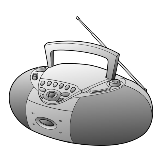
All manuals and user guides at all-guides.com QT-CD180 NAMES OF PARTS 1 2 3 4 5 6 7 18. Battery Compartment 01. Volume Control 10. (TAPE) Record Button 19. FM Telescopic Rod Antenna 02. Function Switch 11. (CD) Play/Pause Button 03. -
Page 4: Operation Manual
All manuals and user guides at all-guides.com QT-CD180 OPERATION MANUAL Quick Guide / Guía rápida Preparation for use / Preparación para su uso Operation with AC power Operation with batteries Turning the power Funccionamiento con corriente alterna Funccionamiento con pilas ON and OFF Conexión (ON) y desconexión (OFF) -
Page 5: Disassembly
All manuals and user guides at all-guides.com QT-CD180 DISASSEMBLY (B3)x1 Open Caution on Disassembly ø3x8mm Cassette Follow the below-mentioned notes when disassembling the Holder unit and reassembling it, to keep it safe and ensure excellent Main Tape performance: Mechanism 1. Take cassette tape and compact disc out of the unit. 2. -
Page 6: Removing And Reinstalling The Main Parts
All manuals and user guides at all-guides.com QT-CD180 REMOVING AND REINSTALLING THE MAIN PARTS TAPE MECHANISM SECTION Perform steps 1 to 4 of the disassembly method to remove the tape mechanism. (See page 5.) How to remove the record / playback and erase Hook (A1) x1 heads (See Fig. - Page 7 All manuals and user guides at all-guides.com QT-CD180 How to remove the flywheel (See Fig. 7-1.) (E1) x 1 Stop Washer 1. Remove the belt. (See Fig. 6-3.) 2. Remove the stop washer (E1) x 1 pc., with a small precision screwdriver to extract the flywheel from the capstan metal.
-
Page 8: Adjustment
All manuals and user guides at all-guides.com QT-CD180 ADJUSTMENT MECHANISM SECTION TUNER SECTION • Driving Force Check fL: Low-range frequency fH: High-range frequency Torque Meter Specified Value • FM IF/RF PLAY: TW-2412 Over 80 g Specified Instrument Test Stage • Torque Check Value/Adjusting Connection Point... - Page 9 All manuals and user guides at all-guides.com QT-CD180 CD SECTION Since this CD system incorporates the following automatic adjustment function, when the pickup is replaced, it is not necessary to readjust it. Since this CD unit does not need adjustment, the combination of PWB and laser pickup unit is not restricted. TEST MODE Start While holding down the "Stop"...
- Page 10 All manuals and user guides at all-guides.com QT-CD180 SETTING METHOD FOR LASER LIGHT UP 1. In Power OFF state, set the Function switch to ON, keeping to be pressed the "Stop" and "Up" button at same time. After CD initialize finish. The CD TEST mode is set, and the LCD indicate to the total tracks of the disc. Release the PLAY button. The CD TEST mode is set when the LCD indicate to "...
-
Page 11: Notes On Schematic Diagram
All manuals and user guides at all-guides.com QT-CD180 NOTES ON SCHEMATIC DIAGRAM • Resistor: 1. Tuner To differentiate the units of resistors, such symbol as K and ( ) : AM mode : FM mode M are used: the symbol K means 1000 ohm and the symbol 2. -
Page 12: Schematic Diagram
All manuals and user guides at all-guides.com QT-CD180 C825 ( ): CD STOP SWITCHING 47/16 3.72V(5.0V) 1.87V(1.45V) R801 C826 IC801 C817 100/10 2.97V SERVO PRE AMP. PICKUP UNIT C815 C816 (4.39V) 47/16 0.022 TA2109F IC801 R802 R804 2.2K L802 0.82µH C801 R805 0.01... - Page 13 All manuals and user guides at all-guides.com QT-CD180 C825 MAIN PWB-A1 47/16 R824 C826 C823 0.022 SW810 CD LID TMAX R821 OPEN/CLOSE LPFN PUSEL2 R827 C827 LPFO PU IN 4.97V 0.015(ML) R843 PVREF MUTE IC801 3.3K C830 VCOF 4.98V ADIN2 1.50V 0.01(ML) VOLTAGE...
-
Page 14: Wiring Side Of P.w.board
All manuals and user guides at all-guides.com QT-CD180 VR201-B R221 C216 C222 C221 C219 VOLUME C220 C218 PWB-A2 R222 R231 R220 R232 C235 VR201 VOLUME C236 C225 CNP201 R219 C217 VR201-A C237 C215 R215 C233 C239 R211 C202 R201 ZD201 C226 C203 D203... - Page 15 All manuals and user guides at all-guides.com QT-CD180 SO651 CNS201 AC INLET SOCKET 3 2 1 AC 120V, 60Hz TAPE M601 SW601 TAPE MOTOR TAPE MAIN (242-6) (242-7) T651 POWER TRANSFORMER SP202 SP201 SPEAKERS R-CH L-CH CNS602 PICKUP UNIT C651 BATTERYS DC9 V [ "D"...
-
Page 16: Waveforms Of Cd Circuit
All manuals and user guides at all-guides.com QT-CD180 WAVEFORMS OF CD CIRCUIT NO DISC FOCUS SEARCH STOP PLAY TMAX IC802 66Pin IC802 50Pin SBOX IC803 20Pin IC802 45Pin IC803 21Pin IC802 72Pin STOP PLAY FOCUS SEARCH TOC IL IC802 64Pin IC802 74Pin IC802 67Pin IC802 62Pin... -
Page 17: Troubleshooting (Cd Section)
All manuals and user guides at all-guides.com QT-CD180 TROUBLESHOOTING (CD SECTION) When the CD does not function When the CD section does not operate when the objective lens of the optical pickup is dirty, this section may not operate. Clean the objective lens, and check the playback operation. - Page 18 All manuals and user guides at all-guides.com QT-CD180 • Laser failure. Is +5V applied to the emitter of Q204 ? Check the PWB pattern of Q204. Check the peripheral parts of IC803 and Q204. Is +5V applied to the collector of Q204 ? Check the PWB pattern between collector of Q204 and pin 75 of Is +5V applied to the pin 75 (VDD) of IC802 ? IC802.
- Page 19 All manuals and user guides at all-guides.com QT-CD180 • Focus servo sawtooth wave failure. IC802 is faulty. Is sawtooh wave output to the pin 66 (FOO) of IC802 ? 1.5~2.5sec Check the PWB pattern of IC803. Is +8.1V applied to the pins 21 and 22 (VCC) of IC803 ? Check the PWB pattern of IC803.
- Page 20 All manuals and user guides at all-guides.com QT-CD180 • Track search failure Does the sled motor run in FF/REW state when the CD Check as stated in item "SLED MOTOR OPERATION FAILURE". TEST MODE is set ? Is the following wave output to the pin 67 (TRO) of IC802 IC802 failure.
-
Page 21: Function Table Of Ic
All manuals and user guides at all-guides.com QT-CD180 FUNCTION TABLE OF IC IC802 VHiTC9457F0-1: Servo/Signal Control (TC9457F0) (1/4) Pin No. Port Name Terminal Name Input/Output Function (OT5)S1 SEG1 Output Segment signal output to the LCD panel. (OT6)S2 SEG2 Output Up to 72 segments in a matrix with COM1 to COM4 can be displayed. (OT7)S3 SEG3 Output... - Page 22 All manuals and user guides at all-guides.com QT-CD180 IC802 VHiTC9457F0-1: Servo/Signal Control (TC9457F0) (2/4) Pin No. Port Name Terminal Name Input/Output Function (S12)P4-1 PUSEL2 Input 3-bit CMOS I/O ports. (SO/S11/ Input/Output These ports can be set for input or output bit for bit by a program. SDA)P4-2 These pins serve dual purposes as input or output pins for the serial (SCK/SCL)
- Page 23 All manuals and user guides at all-guides.com QT-CD180 IC802 VHiTC9457F0-1: Servo/Signal Control (TC9457F0) (3/4) Pin No. Port Name Terminal Name Input/Output Function SBAD SBAD Input/Output Subbeam add signal input pin. Input/Output Tracking error input pin. This input is read when tracking servo is on. TEZI TEZI Input/Output...
- Page 24 All manuals and user guides at all-guides.com QT-CD180 IC802 VHiTC9457F0-1: Servo/Signal Control (TC9457F0) (4/4) Pin No. Port Name Terminal Name Input/Output Function /HOLD RYNCREC Input This pin is used to input a signal that requests or clears the hold mode. Normally, use this pin for CD mode select signal input or battery detection signal input.
- Page 25 “HOW TO ORDER REPLACEMENT PARTS” To have your order filled promptly and correctly, please furnish the For U.S.A. only following information. Contact your nearest SHARP Parts Distributor to order. 1. MODEL NUMBER 2. REF. No. 3. PART NO. 4. DESCRIPTION For location of SHARP Parts Distributor, Please call Toll-Free;...
- Page 26 All manuals and user guides at all-guides.com QT-CD180 PRICE PRICE PARTS CODE DESCRIPTION PARTS CODE DESCRIPTION RANK RANK AB 0.022 µF,50V INTEGRATED CIRCUITS VCKYPA1HF223Z VCCCPA1HH100J AA 10 pF (CH),50V AB 1 µF,50V,Electrolytic C16,17 RC-GZA105AF1H VHITA2111N/-1 AN FM/AM IF MPX.,TA2111N AB 0.015 µF,50V,Mylar C18,19 VCQYKA1HM153K J IC101...
- Page 27 All manuals and user guides at all-guides.com QT-CD180 PRICE PRICE PARTS CODE DESCRIPTION PARTS CODE DESCRIPTION RANK RANK RESISTORS OTHER CIRCUITRY PARTS VRD-ST2CD331J AA 330 ohms,1/6W BI801/CNS801 QCNWN0250SJZZ J AE Connector Ass’y,8/8Pin VRD-ST2CD272J AA 2.7 kohms,1/6W BI802/CNS802 QCNWN0251SJZZ J AE Connector Ass’y,5/5Pin VRD-ST2CD224J AA 220 kohms,1/6W BI803/CNS803 QCNWN0252SJZZ J...
- Page 28 All manuals and user guides at all-guides.com QT-CD180 PRICE PARTS CODE DESCRIPTION RANK LHLDZ3007SJFW Cover,Power PWB MLEVP0005SJZZ AD Lever,Record MSPRC0008SJFD AD Spring,Battery,+/- MSPRC0009SJFN Spring,Battery,- MSPRD0016SJFD AD Spring,Cassette Holder MSPRZ0003SJFD AD Spring,Rod Antenna NDRM-0004SJZZ AD Drum PGUMS0001SJZZ AB Cushion,CD Lid QANTR0007SJZZ AG FM Rod Antenna TSPC-0197SJZZ Label,Specifications...
- Page 29 All manuals and user guides at all-guides.com QT-CD180 703x2 M702 M701 305x2 SW702 PWB-B Figure 4 CD MECHANISM EXPLODED VIEW – 4 –...
- Page 30 All manuals and user guides at all-guides.com QT-CD180 241-2 241-1 PWB-A1 242(242-1, 605x2 242-2,242-3, 242-4,242-5, PWB-A2 242-6(M601), 242-7(SW601)) SW810 602x2 605x2 605x5 TAPE LCD801 MECHANISM MECHANISM PWB-A3 605x2 PWB-A5 607x2 603x3 T651 606x2 SO651 606x2 605x2 PWB-A4 605x2 SP202 605x2 SP201 BELT CONNECTION Motor...
-
Page 31: Packing Of The Set (For U.s.a. Only)
All manuals and user guides at all-guides.com QT-CD180 PACKING OF THE SET (FOR U.S.A. ONLY) • Setting position of switches and knobs Tape Mechanism Control STOP STATE TUNING FUNCTION SELECTOR VOLUME DOWN Polyethylene Bag, Unit SSAKH0001SJZZ Battery Compartment Lid Energy Star Label TLABZ0031SJSC Operation Manual Packing Add., Left/Right... - Page 32 All manuals and user guides at all-guides.com QT-CD180 © COPYRIGHT 2001 BY SHARP CORPORATION ALL RIGHTS RESERVED. No part of this publication may be reproduced, stored in a retrieval system, or transmitted in any form or by any means, electronic, mechanical, photocopying, recording, or otherwise, without prior written permission of the publisher.