
Related Manuals for Motorola RMU2080d


Summary of Contents for Motorola RMU2080d
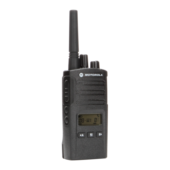
- Page 1 All manuals and user guides at all-guides.com Two-Way Radios User Guide RMU2080d Display model...
- Page 2 All manuals and user guides at all-guides.com...
-
Page 3: Table Of Contents
All manuals and user guides at all-guides.com Battery Features..... . 15 CONTENTS About the Li-Ion Battery ... . . 15 Battery Recycling and Disposal . - Page 4 All manuals and user guides at all-guides.com Signal Strength Indicator and Programming Scramble ....39 Channel Busy Indicators ...30 Programming Maximum Number Talk Range .
- Page 5 All manuals and user guides at all-guides.com Cloning with a Multi Unit Carry Accessories ....77 Charger (MUC) ....51 Software Applications.
-
Page 6: Product Safety
All manuals and user guides at all-guides.com For a list of Motorola-approved antennas, PRODUCT SAFETY batteries and other accessories, visit the following website which lists approved PRODUCT SAFETY AND RF accessories: EXPOSURE COMPLIANCE www.motorolasolutions.com/RMseries Before using this product, read the operating... -
Page 7: Introduction
Thank you for purchasing the Motorola® RM 8000 West Sunrise Boulevard Series™ Radio. This radio is a product of Plantation, Florida 33322 Motorola's 80 plus years of experience as a world leader in the designing and PACKAGE CONTENTS manufacturing of communications equipment. - Page 8 All manuals and user guides at all-guides.com For a copy of a large-print version of this user guide or for product-related questions, contact 1-800-448-6686 in the USA 1-800-461-4575 in Canada 1-888-390-6456 on TTY (Text Telephone) For product related information, visit us at: www.motorolasolutions.com/RMseries...
-
Page 9: Fcc Licensing Information
All manuals and user guides at all-guides.com To transmit on these frequencies, you are FCC LICENSING required to have a license issued by the FCC. INFORMATION Application is made available on FCC Form 601 and Schedules D, H, and Remittance Form INTERFERENCE INFORMATION 159. - Page 10 Motorola Product Services at: Use of this radio outside the country where it 1-800-448-6686 was intended to be distributed is subject to government regulations and may be prohibited Changes or modifications not expressly approved by Motorola may void the user’s...
-
Page 11: Batteries And Chargers Safety
All manuals and user guides at all-guides.com To reduce risk of damage to the electric plug BATTERIES AND and cord, pull by the plug rather than the cord CHARGERS SAFETY when disconnecting the charger. INFORMATION An extension cord should not be used unless absolutely necessary. - Page 12 All manuals and user guides at all-guides.com OPERATIONAL SAFETY located at the bottom of the charger. GUIDELINES • Make sure that the cord is located where it will not be stepped on, tripped over, or subjected to • Turn the radio OFF when charging battery. water, damage, or stress.
- Page 13 All manuals and user guides at all-guides.com RADIO OVERVIEW PARTS OF THE RADIO Channel Selector Knob Antenna On/Off/Volume Knob...
- Page 14 All manuals and user guides at all-guides.com On/Off/Volume Knob Front Buttons Used to turn the radio ON or OFF and to adjust the radio’s volume. Channel Selector Knob Used to switch the radio to different channels. Accessory Connector Used to connect compatible audio accessories.
- Page 15 All manuals and user guides at all-guides.com Side Buttons • Programmable Button Push-to-Talk (PTT) Button Allows you to choose level or toggle options for • Press and hold down this button to talk, release it features the Menu is on. to listen.
- Page 16 All manuals and user guides at all-guides.com This User Guide covers the RMU2080d model from the RM Series radios. The radio’s model is shown on the bottom of the radio and provides the following information: Table 1: RMU2080d Radio Specifications...
-
Page 17: Battery Features
Motorola batteries are designed specifically to the battery life. be used with a Motorola charger and vice About the Li-Ion Battery versa. Charging in non-Motorola equipment may lead to battery damage and void the The RM Series radio comes equipped with a battery warranty. -
Page 18: Battery Recycling And Disposal
All manuals and user guides at all-guides.com Battery Recycling and Disposal Many retailers and dealers participate in this program. For the location of the drop-off facility Li-Ion rechargeable batteries can be recycled. closest to you, access RBRC's Internet web However, recycling facilities may not be site at: available in all areas. -
Page 19: Installing The Lithium-Ion
All manuals and user guides at all-guides.com Installing the Lithium-Ion (Li-Ion) Battery Removing the Lithium-Ion (Li-Ion) Battery Detach Attach Press Latch Press until click... -
Page 20: Holster
All manuals and user guides at all-guides.com Holster Power Supply, Adaptor and Drop-in Tray Charger... - Page 21 All manuals and user guides at all-guides.com Battery Life Information When the Battery Save feature is set to ON (enabled by default), the battery life lasts longer. The following table summarizes battery life estimations: Table 2: Li-Ion Battery Life with Tx Power 2 Watts Battery Type Battery Save OFF Battery Save ON...
- Page 22 All manuals and user guides at all-guides.com Battery Meter The battery meter located in the upper left corner of the radio display indicates how much battery power the radio has remaining. Table 3: RM Series Battery Meter Battery Meter Battery Type 3 Bars 2 Bars 1 Bar...
- Page 23 Drop-in Tray • Standard Power Supply and, Power Supply SUC Port • Rapid Power Supply (Transformer) Note: The radio comes with a Standard Power Supply. To charge the battery (with the radio attached), place it in a Motorola-approved Drop-in Tray...
- Page 24 OFF to ensure a full alignment ribs in the Drop-in Tray Single Unit charge. See “Operational Safety Guidelines” Charger. on page 10 for more information. Table 4: Motorola Authorized Batteries Charging A Stand-Alone Battery Part Number Description PMNN4434_R...
- Page 25 All manuals and user guides at all-guides.com Drop-in Tray Charger LED Indicators Table 5: Charger LED Indicator Status LED Indicator Comments Green for approximately 1 second Power On Steady Red Charging Steady Green Charging Complete...
- Page 26 All manuals and user guides at all-guides.com If there is NO LED indication: Check if the radio with battery, or the battery alone, is inserted correctly. (refer to step 4 of "Charging with the Drop-in Tray Single Unit Charger (SUC)" on page 21) Ensure that the power supply cable is securely plugged into the charger socket using an appropriate AC outlet and there is power to the outlet.
- Page 27 All manuals and user guides at all-guides.com Charging a Radio and Battery using Place the Multi-Unit Charger on a flat surface. a Multi Unit-Charger - MUC (Optional Insert the power cord plug into the MUC’s dual Accessory) pin connector at the bottom of the MUC. Plug the power cord into an AC outlet.
- Page 28 All manuals and user guides at all-guides.com Multi-Unit Charger LED Indicators Table 7: Charger LED Indicator Status LED Indicator Comments Green for approximately 1 second Power On Steady Red Charging Steady Green Charging Complete...
- Page 29 All manuals and user guides at all-guides.com If there is NO LED indication: Check if the radio with battery or the battery alone, is inserted correctly (refer to step 5 of "Charging a Radio and Battery using a Multi Unit-Charger - MUC (Optional Accessory)" on page 25).
- Page 30 All manuals and user guides at all-guides.com Note: Do not hold the radio too close to the ear GETTING STARTED when the volume is high or when adjusting the volume For the following explanations, refer to “Parts Of The Radio” on page 11. READING THE DISPLAY Keypad TURNING RADIO ON/OFF...
- Page 31 All manuals and user guides at all-guides.com SELECTING A CHANNEL Notes: To select a channel, turn the Channel Selector • To listen to all activity on a current channel, short Knob until you reach the desired channel. An press the SB1 to set the CTCSS/DPL code to 0. audible voice indicates the selected channel.
-
Page 32: Signal Strength Indicator And Channel Busy Indicators
All manuals and user guides at all-guides.com Signal Strength Indicator and Channel Busy TALK RANGE Indicators TALK RANGE When there is activity on a frequency, the radio Industrial Multi-Level displays the Signal Strength Indicator icon and the radio LED blinks faster. When your Model Inside steel/ Inside multi-... - Page 33 All manuals and user guides at all-guides.com To establish a proper two-way communication, Scramble Code: Codes that make the the channel, frequency, and interference transmissions sound garbled to anyone eliminator codes must be the same on both listening who is not set to that specific code. radios.
-
Page 34: Radio Led Indicators
All manuals and user guides at all-guides.com RADIO LED INDICATORS RADIO STATUS LED INDICATION Channel Busy Solid Orange Cloning Mode Double Orange Heartbeats Cloning In Progress Solid Orange One Green Blink, One Orange Blink, One Green Blink, then repeat for 4 Fatal Error at Power up seconds Low Battery... -
Page 35: Hands-Free Use/Vox
All manuals and user guides at all-guides.com HANDS-FREE USE/VOX Open accessory cover. Insert the audio accessory’s plug firmly into accessory port. Turn radio ON. The LED Indicator will blink double red Lower radio volume BEFORE placing accessory near ear. To transmit, speak into accessory microphone... -
Page 36: Hands Free Without Accessories
All manuals and user guides at all-guides.com Hands Free without Accessories (iVOX) hear the pre-programmed power up tone. 3 different power-up tones are available: • Press the PTT button while turning ON the radio • Power up tone and channel number blinks. - Page 37 All manuals and user guides at all-guides.com Keypad Lock/Unlock MENU OPTIONS To access the radio MENU, short press the You can lock the keypad to avoid accidentally (Menu) button. The radio displays the changing your radio settings. To lock the radio feature options.
- Page 38 All manuals and user guides at all-guides.com Accessories (iVOX)” on page 34 for more • 1 = Low sensitivity information). Once VOX/iVOX is enabled, short • 2 = Medium sensitivity press the (Menu) button. • 3 = High sensitivity If iVOX is enabled when you press the Once you have selected the desired sensitivity (Menu) button, the radio displays the following: level, you can:...
- Page 39 All manuals and user guides at all-guides.com When the radio is set to Advanced PROGRAMMING Configuration Mode, the icon displays FEATURES and the current channel aliasing name blinks to indicate that you can rotate the Channel ADVANCED CONFIGURATION MODE Selector Knob to select the channel you want Advanced Configuration mode is a special to program.
- Page 40 All manuals and user guides at all-guides.com (Menu) button to scroll through the options until • To move along the different Programming Selection Mode without saving changes, short you reach ‘Frequency Programming Mode’. The radio display shows the frequency code as press the PTT Button or (Menu) Button.
-
Page 41: Programming Scramble
All manuals and user guides at all-guides.com The radio display shows the CTCSS/DPL code Once you have entered Advanced as follows: Configuration Mode and selected the channel in which you want to enable Scramble ( ), scroll up or down through the programming modes by short pressing the PTT button or (Menu) button until the radio reaches the Scramble Programming Mode. -
Page 42: Programming Maximum Number
All manuals and user guides at all-guides.com maximum number of channels. Long press the the CPS. Scramble is disabled when the value is set to ‘0’. PTT button to exit and save, or short press the PTT button to move to the next programming PROGRAMMING MAXIMUM NUMBER OF feature without saving. -
Page 43: Programming Microphone Gain Level
All manuals and user guides at all-guides.com Tones’ selection by short pressing the PTT via the CPS. Call Tones is disabled when the value is set to ‘0’. button or (Menu) button. The radio display shows the Programming Call PROGRAMMING MICROPHONE GAIN Tone’... -
Page 44: Gain Level
All manuals and user guides at all-guides.com medium gain or 3 = high gain) by pressing the buttons. Once you have selected the desired Microphone Gain Level, long press the PTT button to exit and save, or short press the PTT The radio blinks the current Microphone button to move to the next programming Accessory Gain Level setting. -
Page 45: Other Programming Features
All manuals and user guides at all-guides.com OTHER PROGRAMMING FEATURES Auto-Scan has been enabled for a particular channel, do not press SB1 or SB2 Scan (programmed for scan) to start scanning, as Scan allows you to monitor other channels to the radio does it automatically. - Page 46 All manuals and user guides at all-guides.com Programming Scan List Once you have selected the channel, proceed to enable (‘YES’) or disable (‘NO’) the scan You can enable or disable the Channel feature by pressing the SB2 (*) button. Once Scanning feature for each channel in your you have set the values you need, long press radio.
- Page 47 All manuals and user guides at all-guides.com (Menu) button until you reach the press the PTT button or (Menu) button to ‘Weather Channel Programming Mode’. start editing the channel alias name. Press the buttons to enable or • The character to be changed starts blinking. If it’s disable the mode.
- Page 48 All manuals and user guides at all-guides.com Nuisance Channel Delete CUSTOMER PROGRAMMING SOFTWARE (CPS) Nuisance Channel Delete allows you to temporarily remove channels from the Scan List. This feature is useful when irrelevant conversations on a ‘nuisance’ channel ties up Radio to be programmed the radio’s scanning feature.
- Page 49 All manuals and user guides at all-guides.com To program, connect the RM Series radio via Time-Out Timer the Drop-in Charger Tray and CPS Transmissions can be terminated when the Programming Cable as shown in Figure 1 on PTT button is pressed by setting up a Time-Out page 46.
- Page 50 All manuals and user guides at all-guides.com Reverse Burst WEATHER CHANNEL Reverse Burst eliminates unwanted noise NOAA Weather Radio All Hazards (NWR) is (squelch tail) during loss of carrier detection. a nationwide network of radio stations You can select values of either 180 or 240 to be broadcasting continuous weather information compatible with other radios.
- Page 51 All manuals and user guides at all-guides.com Known as the “Voice of NOAA’s National The channel position 8 on all RM Series radios Weather Service”, NWR is provided as public with channel selector knob is configured at the service by the National Oceanic and factory as a NOAA Weather Radio.
- Page 52 All manuals and user guides at all-guides.com button to advance to channel menu or weather detected. While monitoring an alert, pressing menu alert menu. the PTT button or changing channels exits the weather alert and returns to normal operation. NOAA Weather Alert Note: Using the Weather Alert Feature impacts The RM series radio is capable of monitoring...
-
Page 53: Charger (Muc)
All manuals and user guides at all-guides.com CLONING RADIOS To clone radios using the MUC, there must be at least two radios: You can clone RM Series radio profiles from one Source radio to a Target radio by using any •... - Page 54 1. run successfully. Press and release the SB1 button. • MUC pockets numbers should be read from left to After cloning is completed, the Source radio will right with the Motorola logo facing front. announce either “successful” (cloning is...
-
Page 55: Cps And Cloning Cables (Optional Accessory)
All manuals and user guides at all-guides.com CPS and Cloning Cables (Optional CPS Cable Accessory) • Both CPS and Cloning Cables are made to work either with RM Series radios or RDX Series radios. Cloning cable supports a mix of RM and RDX series radios. -
Page 56: Cloning Radio Using The Radio To Radio (R2R) Cloning Cable (Optional Accessory)
All manuals and user guides at all-guides.com Cloning Radio using the Radio to Radio Unplug any cables (power supply or USB (R2R) Cloning Cable (Optional Accessory) cables) from the SUCs. Plug one side of the cloning cable mini USB connector to the first SUC and the other end to the second SUC. - Page 57 All manuals and user guides at all-guides.com When the cloning is completed, the Source the radio. Radio audible voice will announce either Ensure that there is no debris in the charging “successful” (cloning is successful) or “fail” tray or on the radio contacts. (cloning process has failed).
-
Page 58: Cloning Using The Customer Programming Software (Cps)
All manuals and user guides at all-guides.com Cloning using the Customer Programming Software (CPS) When cloning using this method, you need the Radio to be CPS software, a Drop-In Tray Charger and the programmed CPS Programming Cable. To order the CPS Programming Cable, please refer to P/N# HKKN4028_. - Page 59 All manuals and user guides at all-guides.com TROUBLESHOOTING Symptom Try This... Recharge or replace the Li-Ion battery. No Power Extreme operating temperatures may affect battery life. Refer to “About the Li-Ion Battery” on page 15 Confirm Interference Eliminator Code is set.
- Page 60 All manuals and user guides at all-guides.com Symptom Try This... Steel and/or concrete structures, heavy foliage, buildings or vehicles decrease range. Check for clear line of sight to improve transmission. Wearing radio close to body such as in a pocket or on a belt decreases range. Change location of radio.
- Page 61 All manuals and user guides at all-guides.com Symptom Try This... Radios are too close; they must be at least five feet apart. Heavy static or interference Radios are too far apart or obstacles are interfering with transmission. Refer to “Talking and Monitoring” on page 29. Recharge or replace Li-Ion battery.
- Page 62 All manuals and user guides at all-guides.com Symptom Try This... VOX feature might be set to OFF. Use the CPS to ensure that the VOX Sensitivity level is not set to ‘0’. Cannot activate VOX Accessory not working or not compatible. Refer to “Hands-Free Use/VOX”...
- Page 63 All manuals and user guides at all-guides.com USE AND CARE...
- Page 64 All manuals and user guides at all-guides.com FREQUENCY AND CODE CHARTS RM UHF FREQUENCIES CHART RM UHF Frequencies Frequency # Frequency (MHz) Bandwidth Frequency # Frequency (MHz) Bandwidth 464.5000 12.5 kHz 461.1875 12.5 kHz...
- Page 65 All manuals and user guides at all-guides.com RM UHF Frequencies (Continued) Frequency # Frequency (MHz) Bandwidth Frequency # Frequency (MHz) Bandwidth 462.9125 12.5 kHz 466.3625 12.5 kHz 464.4875 12.5 kHz 467.7875 12.5 kHz 464.5125 12.5 kHz 467.8375 12.5 kHz 464.5375 12.5 kHz 467.8625 12.5 kHz...
- Page 66 All manuals and user guides at all-guides.com RM UHF Frequencies (Continued) Frequency # Frequency (MHz) Bandwidth Frequency # Frequency (MHz) Bandwidth 451.1875 12.5 kHz 456.1875 12.5 kHz 451.2375 12.5 kHz 456.2375 12.5 kHz 451.2875 12.5 kHz 456.2875 12.5 kHz 451.3375 12.5 kHz 456.3375 12.5 kHz...
- Page 67 All manuals and user guides at all-guides.com RMU2080D – UHF DEFAULT FREQUENCIES CHART RM UHF 8CH Radios Default Frequencies – RMU2080 Frequency Channel Frequency # Code # Code Bandwidth (MHz) 464.5500 67.0 Hz 12.5 kHz 467.9250 67.0 Hz 12.5 kHz...
- Page 68 All manuals and user guides at all-guides.com CTCSS AND PL/DPL CODES CTCSS Codes CTCSS CTCSS CTCSS 67.0 107.2 167.9 71.9 110.9 173.8 74.4 114.8 179.9 77.0 118.8 186.2 79.7 192.8...
- Page 69 All manuals and user guides at all-guides.com PL/DPL Codes Code Code Code...
- Page 70 All manuals and user guides at all-guides.com PL/DPL Codes (Continued) Code Code Code Customized PL Customized PL Customized PL Customized PL...
- Page 71 All manuals and user guides at all-guides.com PL/DPL Codes (Continued) Code Code Code Inverted DPL 48 Inverted DPL 65 Inverted DPL 82 Inverted DPL 49 Inverted DPL 66 Inverted DPL 83 Inverted DPL 50 Inverted DPL 67 Inverted DPL 84 Inverted DPL 51 Inverted DPL 68 Inverted DPL 85...
- Page 72 All manuals and user guides at all-guides.com PL/DPL Codes (Continued) Code Code Code Inverted DPL 99 Inverted DPL 109 Inverted DPL 119 Inverted DPL 100 Inverted DPL 110 Inverted DPL 120 Inverted DPL 101 Inverted DPL 111 Inverted DPL 121 Inverted DPL 102 Inverted DPL 112 Inverted DPL 123...
- Page 73 All manuals and user guides at all-guides.com Notes...
- Page 74 What Does this Warranty Cover? provided for below. provided for below. Subject to the exclusions contained below, Motorola, Inc. warrants its telephones, pagers, and Decorative Accessories and Limited lifetime warranty consumer and business two-way radios (excluding...
- Page 75 Use of Non-Motorola Products and Accessories. Defects or damage that result from Normal Wear and Tear. Periodic maintenance, the use of Non-Motorola branded or certified repair and replacement of parts due to normal Products, Accessories, Software or other wear and tear are excluded from coverage.
- Page 76 All manuals and user guides at all-guides.com Communication Services. Defects, damages, or Software NOT Embodied in Physical Media. the failure of Products, Accessories or Software Software that is not embodied in physical media due to any communication service or signal you (e.g.
- Page 77 United States of America. The any license under the copyrights, patents, or Governments of the United States of America may patent applications of Motorola or any third party restrict the exportation or re-exportation of this software provider, except for the normal, non- product to certain destinations.
- Page 78 All manuals and user guides at all-guides.com BATTERY ACCESSORIES Part No. Description AUDIO ACCESSORIES PMNN4434_R Standard Li-Ion Battery Part No. Description PMNN4453_R High Capacity Li-Ion Battery 53815 Headset w/Boom Mic BR CABLES HMN9026_R Remote Speaker Mic BR...
-
Page 79: Carry Accessories
All manuals and user guides at all-guides.com CARRY ACCESSORIES Part No. Description HKLN4510_ Swivel Holster SOFTWARE APPLICATIONS Part No. Description... - Page 80 All manuals and user guides at all-guides.com Notes...
-
Page 81: Rm Series™ Features Summary
All manuals and user guides at all-guides.com RM Series™ Features Summary Programmable Via Programmable via Advanced Configuration Features Default Value Programming Tips Non- Non- Display Display Display Display Backlight 5 Seconds Choose the backlight’s time out by using the CPS. Battery Save Toggle ON/OFF via CPS only. - Page 82 All manuals and user guides at all-guides.com Programmable Via Programmable via Advanced Configuration Features Default Value Programming Tips Non- Non- Display Display Display Display Only Display Models. To enter or exit Channel Aliasing mode press PTT and buttons Channel simultaneously while turning radio ON for 3 sec. Aliasing After editing, to exit and save, long press the PTT.
- Page 83 All manuals and user guides at all-guides.com Programmable Via Programmable via Advanced Configuration Features Default Value Programming Tips Non- Non- Display Display Display Display Enables radio to enter cloning mode in order to clone its profile settings into other radios (using Radio to Radio Cloning Cable or Multi-Unit Cloning Mode ENABLED...
- Page 84 All manuals and user guides at all-guides.com Programmable Via Programmable via Advanced Configuration Features Default Value Programming Tips Non- Non- Display Display Display Display Radios Bandwidth is fixed and non-programmable. Bandwidth Model Dependant Bandwidth Range for 2W radios: VHF 150.8 - 160 Range Mhz / UHF 450-470 Mhz.
- Page 85 All manuals and user guides at all-guides.com Programmable Via Programmable via Advanced Configuration Features Default Value Programming Tips Non- Non- Display Display Display Display Press and hold (MENU) button for 4 seconds Keypad Lock UNLOCKED to lock the radio keypad. To unlock, press (MENU) button for 4 seconds.
- Page 86 All manuals and user guides at all-guides.com Programmable Via Programmable via Advanced Configuration Features Default Value Programming Tips Non- Non- Display Display Display Display Microphone For front panel programming enter Advanced Medium Gain Level, Configuration Mode (1). (Level 2) RADIO Long Press SB1 to monitor and press SB1 again to release.
- Page 87 All manuals and user guides at all-guides.com Programmable Via Programmable via Advanced Configuration Features Default Value Programming Tips Non- Non- Display Display Display Display Use CPS to program a SBx button to be used for selecting the transmission power level you want for 2W (1W Model Power Select each channel.
- Page 88 All manuals and user guides at all-guides.com Programmable Via Programmable via Advanced Configuration Features Default Value Programming Tips Non- Non- Display Display Display Display Short press SB2 to enable/disable scan. Scan SB2 Button Use CPS for editing Scan List (adding/removing channels to be scanned).
- Page 89 All manuals and user guides at all-guides.com Programmable Via Programmable via Advanced Configuration Features Default Value Programming Tips Non- Non- Display Display Display Display Front panel radio programming available in display models by pressing PTT or (MENU) buttons Sensitivity (level 0) Level and scrolling down/up with buttons to set value.
-
Page 90: New Features
All manuals and user guides at all-guides.com New Features Programmable Via Programmable via Advanced Configuration Features Default Value Programming Tips Non- Non- Display Display Display Display This feature prevents radio’s transmitter from being Channel Busy activated if a signal strong enough to break through Lock Out... - Page 91 All manuals and user guides at all-guides.com Programmable Via Programmable via Advanced Configuration Features Default Value Programming Tips Non- Non- Display Display Display Display Set the current channel with high priority scan. If Weather Alert is enabled and the radio is in two-way Priority Scan radio mode, the radio shall enable Weather Alert Scan and ignore public priority scan, talkaround...
-
Page 92: Programmable Buttons Chart
All manuals and user guides at all-guides.com Programmable Buttons Chart Button Monitor Scan / Nuisance Delete Call Tone Power Select Scramble Backlight No Operation Default Default Default BUTTON A (*) Default... -
Page 93: Icons Chart
All manuals and user guides at all-guides.com Icons Chart Icon Symbol Comments Battery Level Displayed during normal radio mode operation, displays battery life remaining Channel Displayed during normal radio operation and when programming channel features... - Page 94 All manuals and user guides at all-guides.com Icon Symbol Comments Scramble Displayed whenever scramble is enabled. Power Select Displayed whenever the channel is transmitting or set to a high-power selection Signal RSSI Display Icon numbers of bars will indicate the strength of the received signal. Strength...
- Page 95 All manuals and user guides at all-guides.com...
- Page 96 All manuals and user guides at all-guides.com...