Advertisement
Quick Links
Quick Reference Guide
For detailed information, please refer to the LNL-500 tab in the
Guide (49289).
1.0
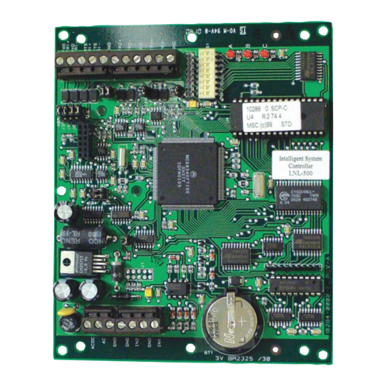
The ISC Board
The ISC board contains the following
components (Refer to Figure 1):
A.
two (2) unsupervised alarm inputs
B.
one (1) RS-232 or RS-485 interface
C. two (2) downstream RS-485 interfaces
(which can consist of one 4-wire and
two 2-wire interfaces)
D. a set of three (3) status LEDs
E.
one (1) bank of eight (8) dip switches
F.
eleven (11) jumpers
G. one (1) power-in input
H. and one (1) memory backup
(3 volt lithium) battery
I.
one (1) TCP/IP Connector
1.1
Unsupervised Alarm Input Wiring
CABINET
TAMPER
POWER
FAULT
Figure 2: Unsupervised Alarm Input Wiring
LNL-500
GND
IN2
GND
IN1
Intelligent System Controller
READYKEYPRO
Figure 1: LNL-500
If either of these inputs is not used, a jumper
wire should be installed.
If RS-485 communication is used, an RS-232
to RS-485 converter is required at the host
workstation.
Hardware Installation
Advertisement

Related Manuals for Bosch READYKEY PRO LNL-500


Summary of Contents for Bosch READYKEY PRO LNL-500
- Page 1 LNL-500 Intelligent System Controller Quick Reference Guide For detailed information, please refer to the LNL-500 tab in the READYKEYPRO Hardware Installation Guide (49289). The ISC Board The ISC board contains the following components (Refer to Figure 1): two (2) unsupervised alarm inputs one (1) RS-232 or RS-485 interface C.
- Page 2 To configure as a 4-wire RS-485 ports, follow the Port 2/3 4-wire diagram (Table 2). TR2+, TR2- TR3+, TR3- Table 2: Ports 2-3, RS-485 Must terminate the RS-485 at each end-of- line device. LNL-500 Quick Reference Guide 49305D Page 2 © 2006 Bosch Security Systems, Inc.
- Page 3 Communication Handshake PASSWORD STATUS: Status SWITCH 8 HANDSHAKE NOT USED Default STATUS: SWITCH 5 Table 7: Password Status Transmit enabled by Default None Table 5: Handshake Status LNL-500 Quick Reference Guide © 2006 Bosch Security Systems, Inc. Page 3 49305D...
- Page 4 Serial or Dial-up Ethernet Configuration for Configuration for Jumper J13 Jumper J13 Figure 11: Port 1 – RS232, Serial, Ethernet Type © 2006 Bosch Security Systems, Inc. 49305D 10/06 130 Perinton Parkway, Fairport, NY 14450-9199 USA Quick Reference Guide LNL-500 Customer Service: (800) 289-0096;...