Panasonic KX-HTS Series Manual
Hybrid ip-pbx
Hide thumbs
Also See for KX-HTS Series:
- Setup reference manual (15 pages) ,
- Quick start manual (2 pages) ,
- Setup reference manual (14 pages)
Table of Contents
Advertisement
Thank you for purchasing this Panasonic product.
Please read this manual carefully before using this product and save this manual for future use.
In particular, be sure to read
KX-HTS
Series
(KX-HTS824
Manuals and supporting information are provided on the Panasonic Web site at:
http://panasonic.net/pcc/support/pbx/
"1.1 For Your Safety (Page
KX-HTS32) :
PJMPR
Getting Started
Model No.
6)" before using this product.
Software File Version
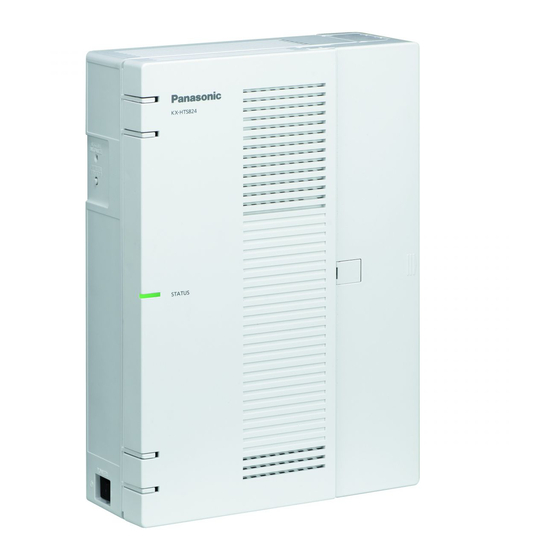
Hybrid IP-PBX
KX-HTS824
KX-HTS32
001.00000
or later
Advertisement
Table of Contents

Related Manuals for Panasonic KX-HTS Series


Summary of Contents for Panasonic KX-HTS Series
- Page 1 In particular, be sure to read "1.1 For Your Safety (Page 6)" before using this product. KX-HTS Series (KX-HTS824 KX-HTS32) : PJMPR Software File Version 001.00000 or later Manuals and supporting information are provided on the Panasonic Web site at: http://panasonic.net/pcc/support/pbx/...
- Page 2 The PBX supports the following equipment: Doorphones ・ Doorphone (KX-T30865, KX-T7765) SIP Phones ・Refer to the Panasonic Web site for information on compatible terminals. Other ・ Single line telephones Note ・ For the equipment that can be connected to a particular telephone, refer to the telephone's manual.
- Page 3 Introduction Introduction This Manual is designed to serve as an overall technical reference for the Panasonic KX-HTS824 KX-HTS32 IP-PBXs. It provides instructions for installing the hardware, and programming the PBX using Web Based programming. The Structure of this Manual This manual contains the following sections: Section 1 Safety Precautions Provides important information intended to prevent personal injury and property damage.
-
Page 4: Table Of Contents
Table of Contents Table of Contents 1 Safety Precautions 1.1 For Your Safety Important Safety Instructions Precautions Data Security 2 System Outline Basic System Construction 2.1.1 System Configurations 2.1.2 System Connection Diagram Optional Equipment 2.2.1 Optional Equipment Specifications 2.3.1 General Description 2.3.2 Characteristics 2.3.3 System Capacity 4 Installation... -
Page 5: Safety Precautions
Section 1 Safety Precautions This section provides important information intended to prevent personal injury and property damage. -
Page 6: For Your Safety
This symbol is used to alert users to a specific operating procedure that must be followed in order to operate the unit safely. Notice Panasonic assumes no responsibility for injuries or property damage resulting from failures arising out of improper installation or operation inconsistent with this documentation. - Page 7 1.1 For Your Safety For All Telephone Equipment ・ Do not install the product in any other way than described in relevant manuals. ・ Do not install the product in a place exposed to rain or moisture, or a place where water, oil, or other liquids can drip or splash onto on the product.
- Page 8 ・ Do not attempt to repair the power cord or plug. If the power cord or plug is damaged or frayed, contact an authorised Panasonic Factory Service Centre for a replacement. ・ If damage to the unit exposes any internal parts, disconnect the power supply cord immediately and return the unit to your dealer.
- Page 9 1.1 For Your Safety For All Telephone Equipment ・ The product should be kept free of dust, moisture, high temperature (more than 40 °C) and vibration, and should not be exposed to direct sunlight. ・ Unplug the product from the wall outlet before cleaning. Wipe the product with a soft cloth. Do not clean with abrasive powders or with chemical agents such as benzine or thinner.
- Page 10 If a call cannot be carried out correctly, there may be a problem with the trunk that the SLT is connected to. Contact your telephone company. If all SLTs operate properly, there may be a problem with your PBX. Do not reconnect the PBX to the trunks until it has been serviced by an authorised Panasonic Factory Service Centre.
-
Page 11: Important Safety Instructions
1.2 Important Safety Instructions 1.2 Important Safety Instructions When using your telephone equipment, basic safety precautions should always be followed to reduce the risk of fire, electric shock and injury to persons, including the following: ・ Do not use the product near water, for example, near a bathtub, wash bowl, kitchen sink, or laundry tub, in a wet basement, or near a swimming pool. -
Page 12: Precautions
1.3 Precautions 1.3 Precautions For users in the European Union only Information for Users on Collection and Disposal of Old Equipment and used Batteries These symbols on the products, packaging, and/or accompanying documents mean that used electrical and electronic products and batteries should not be mixed with general household waste. - Page 13 1.3 Precautions • APPLICABLE ONLY TO TELECOM CUSTOMERS WHO HAVE AUTOMATIC ACCESS TO OTHER CARRIERS FOR TOLL CALLS When calling back a number from the Caller ID list, all numbers prefixed with "0 + AREA CODE" will be automatically forwarded to your toll carrier. This includes numbers in your local calling area. The zero + area code should either be removed when calling back local numbers, or check with your toll carrier that a charge will not be levied.
-
Page 14: Data Security
1.4 Data Security 1.4 Data Security In order to use the PBX safely and correctly, the Security Requirements below must be observed. Failure to do so may result in: ・ Loss, leakage, falsification or theft of user information. ・ Illegal use of the PBX by a third party. ・... -
Page 15: System Outline
Section 2 System Outline This section provides general information on the PBX, including the system capacity and specifications. -
Page 16: Basic System Construction
2.1.1 System Configurations 2.1 Basic System Construction 2.1.1 System Configurations Main Unit The main unit contains a mother board for controlling PBX functions. 2.1.2 System Connection Diagram... - Page 17 2.1.3 Block Diagram 2.1.3 Block Diagram KX-HTS Series...
- Page 18 2.1.4 Typical Network Setting Example 2.1.4 Typical Network Setting Example An example of typical network connection is shown below. (1) When installing in an office that already has a network infrastructure. Note - Dynamic Host Configuration Protocol (DHCP) Server Description The PBX has a built-in DHCP server.
- Page 19 2.1.4 Typical Network Setting Example (2) When installing in a new office or an office where there is no network infrastructure. Notice ・Refer to the following when the internal DHCP server will be used. For details about DHCP server settings, refer to "Network Configuration-[4-2]LAN Settings-◆DHCP Mode in the Programming Item List.
- Page 20 2.1.4 Typical Network Setting Example (3) When installing the PBX without connecting it to an existing network. Notice ・Refer to the following when the internal DHCP server will be used. For details about DHCP server settings, refer to "Network Configuration-[4-2]LAN Settings-◆DHCP Mode in the Programming Item List.
-
Page 21: Optional Equipment
8 ports Standard Telephone Line Interface with Telephone Card Caller ID & Message waiting Lamp(SLC8) KX-HT82460 2-Port Doorphone / Door 2 ports Panasonic Proprietary Door phone Opener Card Interface with door opener (no sensor interface) (DPH2) 2.3 Specifications 2.3.1 General Description... -
Page 22: Characteristics
2.3.2 Characteristics Terminal Equipment Loop Limit • SLT: 600 Ω including set • Doorphone: 20 Ω Minimum Leakage Resistance 15 000 Ω minimum Maximum Number of Extension 1 for SLT Instruments per Line Ring Voltage 75 Vrms at 20 Hz/25 Hz depending on the Ringing Load Trunk Loop Limit 1600 Ω... -
Page 23: System Capacity
2.3.3 System Capacity 2.3.3 System Capacity Type and Maximum Number of Slots The PBX supports the following type and number of slots. Items Maximum Number Remarks Total Trunk (Channel/Port) SIP Trunk (Channel) Analogue Trunk (Port) LCOT4 option card is required Total Extension (Channel/Port) SIP Extension (Channel) Include softphone for smartphone... - Page 24 2.3.3 System Capacity Maximum Optional Service Cards The following number of card can be installed in the Physical Slots or Virtual Slots of the PBX. Note • Any card that exceeds the capacity of the PBX will be ignored. • When the PBX starts up with an invalid configuration, some cards will be ignored. Slot Slot type Card Name...
-
Page 25: Installation
Section 3 Installation This section describes the procedures to install the PBX. Detailed instructions for planning the installation site, installing the main unit and optional service cards, and cabling of peripheral equipment are provided. Further information on peripheral equipment installation is included. - Page 26 Be sure to comply with all applicable laws, regulations, and guidelines. Notice Panasonic assumes no responsibility for injuries or property damage resulting from failures arising out of improper installation or operation inconsistent with this documentation. Safety Installation Instructions WARNING...
- Page 27 3.1.1 Before Installation Wiring Precautions Be sure to follow these instructions when wiring the unit: CAUTION • Avoid using the same AC outlet for computers and other office equipment, as noise generated by such equipment may hamper system performance or interrupt the system. •...
- Page 28 3.2.2 Names and Locations 3.2.2 Names and Locations STATUS Indicator Initialize Switch Switch D Power Switch E Cable Cover F Trunk/Doorphone Free Slot G CO4 Interface H USB Port I WAN port J LAN/WAN port K LAN port Inside View (The front cover is open.) L Extension slot M SLT8 Interface N FG Terminal...
- Page 29 3.2.3 Opening/Closing the front cover 3.2.3 Opening/Closing the front cover Opening the front cover CAUTION 1. Confirm that the power switch is turned off. 2. Turn the screws anticlockwise to loosen them. 3. Slide out the cable cover and turn the screws anticlockwise to loosen them.
- Page 30 3.2.3 Opening/Closing the front cover Closing the front cover 1. Close the front cover. 2. Turn the screws clockwise to tighten them. 3. Slide in the cable cover and turn the screws clockwise to tighten them.
- Page 31 3.2.4 Frame Earth Connection 3.2.4 Frame Earth Connection 1. Loosen the screw. 2. Insert an earthing wire (user-supplied). 3. Tighten the screw. 4. Connect the earthing wire to earth. WARNING • Proper earthing (connection to earth) is very important to reduce the risk to the user of electrocution or to protect the PBX from the bad effects of external noise in the case of a lightning strike.
- Page 32 3.2.5 Installing/Removing the Optional Service Cards 3.2.5 Installing/Removing the Optional Service Cards CAUTION • Before touching the product (PBX, cards, etc.), discharge static electricity by touching ground or wearing an earthing strap. Failure to do so may cause the PBX to malfunction due to static electricity. •...
- Page 33 3.2.5 Installing/Removing the Optional Service Cards Installing an Optional Service Card in the Free Slots In the Main Unit, there are free slots for trunk/doorphone cards and free slots for extension cards. In the free slots for trunk/doorphone cards, you can install one each of the following cards: LCOT4, DPH2. In the free slots for extension cards, you can install one or more of the following card: SLC8.
- Page 34 3.2.5 Installing/Removing the Optional Service Cards 2. Position the card in the open slot, making sure that the tabs on the both sides of the card fit into place. Then, holding the card firmly in place, lower the rear end so that the holes of the card are aligned with the screw holes.
- Page 35 3.2.5 Installing/Removing the Optional Service Cards Removing Optional Service Card from the Free Slot 1. Loosen and remove the spacers (①). ① 2. Holding the rear end of the card, pull the card in the direction of the arrows.
- Page 36 3.2.6 Securing the Cables 3.2.6 Securing the Cables 1. Pass the included strap through either of the 2 slits for securing cables according to your needs. slit slit slit slit 2. Bind the cables as shown. 3. Close the cable cover. ( For details, refer to "3.2.3 Opening/Closing the front cover"...
- Page 37 3.2.6 Securing the Cables Notes • For safety reasons, do not stretch, bend, or pinch the cables. • If you prefer, you can cut the other side of the cable cover and run the cables through that opening. For safety reasons, smooth the cut edges. ・When there are too many cables to fully slide in the the cable cover, leave the cable cover slid open, and tighten the screws with the cable cover in that position.
- Page 38 3.2.7 Placing the PBX on a Desktop 3.2.7 Placing the PBX on a Desktop When placing the PBX on a desktop, make sure to follow these instructions. WARNING Be careful not to drop any components. Dropping components may damage them or cause an injury.
- Page 39 3.2.7 Wall Mounting 3.2.7 Wall Mounting When wall mounting the main unit, use the included screws. WARNING • Make sure that the wall that the unit will be attached to is strong enough to support approximately 5 times the weight of the unit. If not, it is necessary for the wall to be reinforced. •...
- Page 40 3.2.7 Wall Mounting Mounting on a Wooden Wall The included screws may be used when mounting the main unit on a wooden wall. 1. Place the template (found on the last page of this manual) on the wall to mark the 2 screw positions.
- Page 41 3.2.7 Wall Mounting Mounting on a Concrete or Mortar Wall The included screws may be used when mounting the main unit on a concrete or mortar wall. User supplied anchor plugs are also necessary. 1. Place the template (found on the last page of this manual) on the wall to mark the 2 screw positions.
- Page 42 3.2.7 Wall Mounting 4. Hook the main unit on the screw heads.
- Page 43 3.2.8 Surge Protector Installation 3.2.8 Surge Protector Installation CAUTION Performing surge protection is essential. Make sure to follow the instructions in this section. Overview A massive electrical surge can be caused if lightning strikes a telephone cable 10 m above ground, or if a telephone line comes into contact with a power line.
- Page 44 3.2.8 Surge Protector Installation Outside Installation If you install an extension outside of the building, the following precautions are recommended: a. Install the extension wire underground. b. Use a conduit to protect the wire. Note The surge protector for an extension is different from that for trunks. Installation of an Earth Rod 1.
- Page 45 3.2.9 Backup Battery Connection 3.2.9 Backup Battery Connection The backup batteries and Back-up Battery Cable provide a backup power supply to allow full use of the PBX in the event of a power failure. In case of power failure, the backup batteries automatically maintain the power to the PBX without interruption.
- Page 46 3.2.9 Backup Battery Connection Connecting Backup Batteries 1. Turn off the power switch. 2. Connect the Back-up Battery Cable to a backup battery. Backup Batteries (VRLA 12 V DC)
- Page 47 3.3.1 Mother Board 3.3 The Mother Board and Option Cards 3.3.1 Mother Board Function The motherboard has the following functions preinstalled. • Support for up to 8 trunks (SIP trunks and analogue trunks combined) • Support for up to 24 extensions (SIP extensions and analogue extensions combined) The following types of connections are supported for connecting to SIP extensions, SIP trunks, and PCs on private IP networks.
- Page 48 3.3.1 Mother Board Pin Assignments LAN Port/WAN Port (10BASE-T/100BASE-TX) Signal Name Input (I)/Output (O) Function TPO+ Transmit data+ TPO- Transmit data- TPI+ Receive data+ Reserved TPI- Receive data- Reserved LAN Port/WAN Port (1000BASE-T) Signal Name Input (I)/Output (O) Function TRD0 (+) Transmit and receive data 0 (+) TRD0 (-) Transmit and receive data 0 (-)
- Page 49 Indication Colour Description 10BASE-T/ LINK Green Link status indication 100BASE-TX/ • OFF: Off-line 1000BASE-T • ON: Linked normally • Flashing: In communication 1000 Yellow Data transmission speed indication • OFF: Off-line/10 Mbps/100 Mbps • ON: 1000 Mbps WAN/LAN LINK Green Link status indication •...
- Page 50 3.3.2 LCOT4 Card (KX-HT82480) 3.3.2 LCOT4 Card (KX-HT82480) Function 4 analogue trunk ports with Caller ID (FSK/FSK with Call Waiting Caller ID [Visual Caller ID]/DTMF). RJ11 Accessories and User-supplied Items Accessories (included): Spacer x 3 User-supplied (not included): RJ11 connector, Copper wire Note •...
- Page 51 3.3.3 SLC8 Card (KX-HT82470) 3.3.3 SLC8 Card (KX-HT82470) Function 8-port extension card for SLTs with Caller ID (FSK), Message Waiting Lamp control. RJ11 Accessories and User-supplied Items Accessories (included): Spacer x 3 User-supplied (not included): RJ11 connector, Copper wire Note •...
- Page 52 3.3.4 DPH2 Card (KX-HT82460) 3.3.4 DPH2 Card (KX-HT82460) Function A doorphone card for 2 doorphone and 2 door opener. To Door opener To doorphone Accessories and User-supplied Items Accessories (included): Spacer x 3 User-supplied (not included): RJ11 connector, Copper wire Note For details about connecting to a doorphone and/or door opener, refer to "3.6 Connecting Doorphones and Door...
- Page 53 3.4.1 Connecting SIP Trunks 3.4 Connecting Outiside Trunks 3.4.1 Connecting SIP Trunks A typical connection example is shown below for connecting to 2 SIP carriers simultaneously. For details about connecting SIP trunks, refer to "Network Configuration" in the Programming Item List. 1.
- Page 54 3.4.1 Connecting SIP Trunks 4. Connecting via both WAN1 and an external router Note • Up to 2 SIP carriers can be connected to simultaneously. • Trunks ports 1 through 8 can be allocated to SIP carriers. • Each trunk port can be set to a SIP carrier or an analogue line. •...
- Page 55 3.5 Connecting Extensions 3.5 Connecting Extensions 3.5.1 Connecting SIP Extensions A typical connection example for SIP extensions is shown below. The following features can be used with the connection example shown below. 1. Setting IP addresses of SIP phone (automatic setting by DHCP) 2.
- Page 56 3.5 Connecting Extensions For Panasonic SIP devices (for compatible models, see http://panasonic.net/pcc/support/pbx/) Relationships between registration (provisioning), firmware updates, and the installation environment are shown below. Note that each SIP phone extension can be set for whether or not to accept connections from outside networks.
- Page 57 3.5 Connecting Extensions 3.5.1 LAN Connections for IP Telephones When an IP telephone is connected to the LAN and power is supplied for the first time, you will be prompted to set network parameters. The network parameters must be set for the IP telephone before it can be used. Connecting an IP Telephone to a Switching Hub When connecting an IP telephone to the LAN, connect it to a switching hub.
- Page 58 3.5 Connecting Extensions Example: KX-HDV230 AC Adaptor Cord Wall Socket Connecting a PC to an IP Telephone You can connect a PC to some IP telephones using the IP telephone’s secondary port. In this case, only a single port from the LAN’s network interface (switching hub) is required to connect both the IP telephone and PC to the LAN.
- Page 59 3.5 Connecting Extensions 3.5.2 Connecting Analogue Extensions Maximum Cabling Distances of the Extension Wiring(Twisted Cable) Cable Maximum Distance ø 0.4 mm: 698 m ø 0.5 mm: 1128 m ø 0.6 mm: 1798 m Notice The maximum cabling distance may vary depending on the conditions.
- Page 60 3.6 Connecting Doorphones and Door Openers 3.6 Connecting Doorphones and Door Openers Up to 2 doorphones (KX-T30865) and 2 door openers (user-supplied) can be installed. Maximum Cabling Distance Cable Maximum Distance ø 0.42 mm: 70 m ø 0.5 mm: 113 m ø...
- Page 61 3.6 Connecting Doorphones and Door Openers Note Two kinds of screws are included with the doorphone. Please choose the appropriate kind for your wall type. : when a doorphone plate has been fixed to the wall : when you wish to install the doorphone directly onto the wall 3.
- Page 62 3.6 Connecting Doorphones and Door Openers Connecting Door Openers 1. Use a flathead screwdriver to press and hold open the button below the terminal, and insert the wire coming from the door opener into the terminal. 2. Wrap the strap around all of the cords. ( ( For details, refer to "2.2.6 Securing the Cables") Notes...
- Page 63 3.7 Connection of Peripherals 3.7 Connection of Peripherals Maximum Maximum Distance Distance 100 m 100 m Switching Hub Maximum Distance USB Memory Device USB Interface for USB Memory Device The PBX is equipped with a USB 2.0 interface. This interface provides communication between the PBX and user-supplied devices such as a USB memory device.
- Page 64 3.8 Starting the PBX 3.8 Starting the PBX WARNING Make sure that the AC outlet is properly earthed, then securely connect the 3-pin AC plug including the earthed pin. CAUTION • Use only the AC power cord included with the PBX. •...
- Page 65 3.8 Starting the PBX System Initialisation Procedure The system can be reset to its original default state by pressing the Initialize switch while turning the system powe The system initialisation startup operation is as follows. ・Turn on the system power and press and hold the Initialize switch (for 3 seconds). 1.
- Page 66 3.9 Programming Information 3.9 Programming Information 3.9.1 Overview of Web Maintenance Console Web Maintenance Console is designed to serve as an overall system programming reference for the PBX. You can programme and control the PBX over an IP network using Web Maintenance Console. This section describes programming basic items using Web Maintenance Console.
- Page 67 3.9 Programming Information 3.9.2 PC Connection The Main Unit has a LAN port for PC to programme PBX. A default IP address is assigned to each port. A PC can be connected through LAN connection. Port Default IP Address Default Subnet Mask LAN Port 192.168.0.101 255.255.255.0...
- Page 68 3.9 PC Connection Connection via Internet CAUTION It is strongly recommended to use TLS encrypted communication when the PC is accessing the PBX via the Internet. To use TLS encryption, routers must have a port set up for https communication. Notice To access the PBX via the internet, routers must have static NAT/NAPT settings (Port forwarding) enabled.
- Page 69 3.9 PC Connection 3.9.3 Starting Web Maintenance Console System Requirements For the system requirements of the PC (operating system, hardware specifications, supported browsers etc.), refer to "1.3.1 Starting Web Maintenance Console" in the Programming Item List. Copyright for MD5 This software uses the Source Code of RSA Data Security, Inc. described in the RFC1321 (MD5 Message-Digest Algorithm).
- Page 70 3.9 PC Connection 2. Access Web Maintenance Console: LAN or VPN Connection: Launch your Web browser and input the IP address of the PBX followed by the Web Maintenance Console port number into the address bar. The input method will differ according to the PC’s connection to the PBX. The default IP address for the LAN port of the PBX is 192.168.0.101, and the default Web Maintenance Console port number is 80.
- Page 71 3.9 PC Connection 3.9.4 Programming the PBX 3.9.4.1 Easy Setup Wizard In the Easy Setup Wizard, you will set up the mandatory settings required for the PBX. When you log in to Web Maintenance Console for a PBX that is in its initialised, factory default state, the Easy Setup Wizard for that PBX will launch automatically.
- Page 72 3.10.Date and Time setting 3.10.Date and Time setting The following items can be set for the date and time settings. For details about date and time settings, refer to "PBX Configuration-[1-1]System-Date & Time-◆Date & Time" in the Programming Item List. ・Automatic Time Adjustment ・Daylight Saving Adjustment ・Daylight Saving Time...
- Page 73 3.10.Date and Time setting Description Functions Networking Applications DHCP DHCPv4 NTP Client DNSv4 DNS Proxy or Relay DynamicDNS (DDNS) TFTP TFTP Server FTP Server Telnet Server Telnet Server HTTP Server HTTP-1.0 ,Secured-HTTP(HTTPs)
- Page 74 3.12 LAN Connection 3.12 LAN Connection 3.12.1 Wired LAN Connection The PBX is equipped with a LAN port for connecting to a LAN so that IP telephones (SIP phones) and PCs can be connected on a private IP network. When the PBX is connected to the LAN for the first time, you must assign IP addressing information to the PBX.
- Page 75 3.12 LAN Connection Note • Use an Ethernet cable with an RJ45 connector for connection to a switching hub. The cable should be a CAT 5 (Category 5) or higher for 10BASE-T/100BASE-TX, or CAT 5e (Enhanced Category 5) or higher for 1000BASE-T. •...
- Page 76 3.12 LAN Connection c. Connection using manual settings Manually set the necessary settings on the wireless extension. Use the settings of the HTS Series unit for setting the wireless extension's settings. SSID Security type Passphrase CAUTION ・If settings related to security are not performed, the following problems may occur. -Transmission contents may be intercepted by a third party.
- Page 77 4.1 Making and Receiving Calls Section 4 Confirming Connections This section describes the basic checks and operation methods following PBX installation for making and receiving calls to and from extensions and outside lines.
- Page 78 4.1 Making and Receiving Calls The following is a description of the basic checks and operation methods following PBX installation for making and receiving calls to and from extensions and outside lines. 4.1.1 Calling Another Extension To call an extension (Intercom Call) -Follow the operation procedure described below.
- Page 79 5. Maintenance Section 5 Maintenance This section describes maintenance procedures.
- Page 80 Regular Automatic Backup Feature The PBX regularly backs up the system data every 30 minutes. The backup file is saved in the "Panasonic" folder in the internal memory of the main unit. 5.2 Software Upgrading Obtaining software updates (downloading the update to the PBX) can be done manually via Web Maintenance Console.
- Page 81 5. Maintenance 5.3System Initialisation Procedure The system data can be returned to its initial state by following the procedure below. 1. While pressing and holding the Initialize Switch, turn the power ON. The LED will light amber. 2. Continue holding down the Initialize Switch (to confirm the holding). The LED will flash amber at a rate of 240 flashes/minute.
- Page 82 6. Trouble Shooting Section 6 Troubleshooting This section provides information on the PBX and telephone troubleshooting.
- Page 83 6.1.1 Installation 6.1 Troubleshooting 6.1.1 Installation PROBLEM PROBABLE CAUSE SOLUTION You cannot make/receive • Mother board • Replace the mother board (be sure to turn calls via an IP network. malfunction off the PBX when replacing). • Poor connection • Make sure that an 8-pin twisted pair cable is used for connection.
- Page 84 6.1.1 Installation PROBLEM PROBABLE CAUSE SOLUTION The PBX does not operate • Restart the PBX (refer to properly. 6.1.5 Restarting the PBX). • Turn off the power switch, and then turn it back on. • Turn off the power switch, and then unplug the PBX.
- Page 85 6.1.2 Connection 6.1.2 Connection Connection between the PBX and an SLT: CAUSE SOLUTION Can you dial The T/R is connected to the D1/D2. Use the correct cord (the an extension? inner 2 wires are for T/R). If a telephone equipped ●...
- Page 86 6.1.3 Operation 6.1.3 Operation Note For devices connected to a PBX other than the Main Unit, refer to the Troubleshooting for that PBX. PROBLEM PROBABLE CAUSE SOLUTION • Cannot set the IP • An unusable value is • Set an IP address within the valid range. address, subnet mask being set.
- Page 87 6.1.4 Restarting the PBX 6.1.4 Restarting the PBX If the PBX does not operate properly, restart the PBX using Web Maintenance Console. Before restarting the PBX, try the system feature again to confirm whether there definitely is a problem or not. Note •...
- Page 88 Section 7 Appendix This section provides information about System Prompt Languages and the revision history.
- Page 89 – BR: Brazil • No. 1 is set by default. For details, see "PBX Configuration-[1-6]System Options- Language" in the Programming Item List. ◆Prompt System prompt languages stored in the System Memory KX-HTS Series Suffix No.1 LA-Spanish UK-English BR-Portuguese US-English US-English...
- Page 90 Install a screw here. TEMPLATE FOR WALL MOUNTING 1.Copy or print this template and place it on the wall. 2.Install the screws as marked. If you mount the main unit on a concrete or mortar wall, fit anchor plugs(not included) into the wall beforehand.
- Page 91 Web Site: http://www.panasonic.net/ Copyright: This material is copyrighted by Panasonic System Networks Co., Ltd., and may be reproduced for internal use only. All other reproduction, in whole or in part, is prohibited without the written consent of Panasonic System Networks Co., Ltd ©Panasonic System Networks Co., Ltd.