Sony DAV-FX100W Service Manual
Hide thumbs
Also See for DAV-FX100W:
- Operating instructions manual (112 pages) ,
- Specifications (2 pages) ,
- Connecting manual (1 page)
Table of Contents
Advertisement
SERVICE MANUAL
Ver. 1.0 2005.05
• DAV-FX100W is composed of following models.
As service manuals are issued for each component model, please refer to them.
COMPONENT MODEL NAME
COMPACT DISCDECK RECEIVER
AMPLIFIER
PACKAGE SPEAKER
FRONT SPEAKER
SURROUND SPEAKER
CENTER SPEAKER
SUB WOOFER
Sony Corporation
9-879-684-01
Audio Group
2005E16-1
Published by Sony Engineering Corporation
© 2005.05
DAV-FX100W
DAV-FX100W
HCD-FX100W
TA-WR2
SS-GS24
SS-TS46
SS-TS46B
SS-CT46
• Abbreviation
SS-WS42
CND : Canadian model
PARTS LIST
Part No.
Description
ACCESSORIES
************
1-479-227-12 COMMANDER, STANDARD (RM-ADP002)
1-754-059-12 ANTENNA, LOOP (AM)
1-754-147-41 ANTENNA (FM)
1-769-108-11 CORD, CONNECTION (1.5m)
1-824-003-11 CORD (WITH CONNECTOR)(RED, 5m)
1-824-003-31 CORD (WITH CONNECTOR)(WHITE, 5m)
1-824-003-41 CORD (WITH CONNECTOR)(GRAY, 15m)
1-824-003-51 CORD (WITH CONNECTOR)(BLUE, 15m)
1-824-003-61 CORD (WITH CONNECTOR)(GREEN, 5m)
1-830-063-21 CORD (WITH CONNECTOR)(PURPLE, 5m)
2-590-764-11 MANUAL, INSTRUCTION (ENGLISH)
2-590-764-21 MANUAL, INSTRUCTION (FRENCH)(CND)
2-593-972-02 COVER, TERMINAL (FOR SPEAKER)
2-599-807-01 FOOT, WALL HOOK
7-682-565-04 SCREW +B4X16 (FOR SPEAKER)
Canadian Model
Remark
(Including Battery Cover)
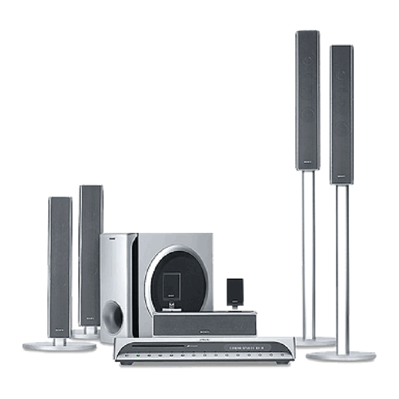
DVD HOME THEATRE SYSTEM
US Model
Advertisement
Table of Contents

Related Manuals for Sony DAV-FX100W


Summary of Contents for Sony DAV-FX100W
- Page 1 DAV-FX100W SERVICE MANUAL US Model Canadian Model Ver. 1.0 2005.05 • DAV-FX100W is composed of following models. As service manuals are issued for each component model, please refer to them. COMPONENT MODEL NAME DAV-FX100W COMPACT DISCDECK RECEIVER HCD-FX100W AMPLIFIER TA-WR2...
- Page 2 DAV-FX100W REVISION HISTORY Clicking the version allows you to jump to the revised page. Also, clicking the version at the upper right on the revised page allows you to jump to the next revised page. Ver. Date Description of Revision...
- Page 3 7.8 kg 300 × 79 × 116 mm Dimensions (approx.) (w/h/d) Design and specifications are subject to change Mass (approx.) 1.2 kg without notice. SUBWOOFER/SPEAKER SYSYTEM Sony Corporation 9-879-632-03 2005L16-1 Home Audio Division © 2005.12 Published by Sony Engineering Corporation...
- Page 4 SS-CT46/GS24/TS46/TS46B/WS42 EXPLODED VIEWS NOTE: • The mechanical parts with no reference number in the exploded views are not supplied. • -XX, -X mean standardized parts, so they may have some differences from the original one. SS-CT46 supplied supplied supplied supplied Ref.
- Page 5 SS-CT46/GS24/TS46/TS46B/WS42 Ver. 1.2 SS-TS46/TS46B supplied supplied not supplied supplied supplied Ref. No. Part No. Description Remark Ref. No. Part No. Description Remark X-2055-373-1 FRAME ASSY, GRILLE (P)(TS46B) 4-251-067-01 PACKING (AL FRONT) 2-048-751-01 SCREW +BVTP 3.5X14 TYPE2 1-694-836-11 TERMINAL, SPEAKER A-1111-452-A CABINET ASSY, SPK (P)(TS46) X-2055-645-1 POLE (L) SUB ASSY, STAND A-1111-472-A CABINET ASSY, SPK (P)(TS46B) X-2055-646-1 POLE (S) SUB ASSY, STAND...
- Page 6 SS-CT46/GS24/TS46/TS46B/WS42 SS-WS42 supplied supplied supplied Ref. No. Part No. Description Remark X-2055-005-1 PANEL ASSY, FRONT 4-874-614-52 SCREW (1)(3.5X20), TAPPING 1-826-186-11 LOUDSPEAKER (20cm)
- Page 7 SS-CT46/GS24/TS46/TS46B/WS42 MEMO...
- Page 8 SS-CT46/GS24/TS46/TS46B/WS42 REVISION HISTORY Clicking the version allows you to jump to the revised page. Also, clicking the version at the upper right on the revised page allows you to jump to the next revised page. Ver. Date Description of Revision 2005.04 2005.09 Addition of E and Australian models...
- Page 9 Power consumption 50 W × × Dimensions (approx.) 260.5 58 mm (w/h/d) Mass (approx.) 1.45 kg Design and specifications are subject to change without notice. SURROUND AMPLIFIER Sony Corporation 9-879-677-03 Audio Group 2005H16-1 Published by Sony Engineering Corporation © 2005.08...
- Page 10 PIÈCES SONT CRITIQUES POUR LA SÉCURITÉ DE 3-2. RX Board, DIAT POWER Board Section ....... 18 FONCTIONNEMENT. NE REMPLACER CES COM- POSANTS QUE PAR DES PIÈCES SONY DONT LES NUMÉROS SONT ELECTRICAL PARTS LIST ........19 DONNÉS DANS CE MANUEL OU DANS LES SUPPLÉMENTS...
- Page 11 TA-WR2 SECTION 1 GENERAL This section is extracted from instruction manual. Surround amplifier POWER/ON LINE POWER Front panel Rear panel SPEAKER DIR-R2 SURROUND L SURROUND R A POWER/ON LINE indicator (33) C DIR-R2 jack (15) B POWER (33) D SPEAKER jacks (15)
- Page 12 TA-WR2 SECTION 2 DIAGRAMS • Note for Printed Wiring Boards and Schematic Diagrams Note on Printed Wiring Boards: Note on Schematic Diagrams: • X : parts extracted from the component side. • All capacitors are in µF unless otherwise noted. (p: pF) •...
- Page 13 TA-WR2 2-1. BLOCK DIAGRAM IC102 IC109 IC110 IC111 RF DEMODULATOR AND GATE STREAM PROCESSOR POWER AMP A/D CONVERTER L101 T100 J100 DATA 10 ADVIN 2 PWMBP DAOUT DATA OUTL1 OUT B REAR RCH+ DIR-R2 OUT B REAR RCH- REAR LCH+ OUTL2 PWMAP 30 BCK...
- Page 14 TA-WR2 2-2. PRINTED WIRING BOARD — DIAT POWER SECTION — :Uses unleaded solder. • Semiconductor Location Ref. No. Location D901 D902 D904 D905 D906 D907 AEP, UK, RU D908 D909 AEP, UK, RU D910 RX BOARD D911 D913 CN102 D914 (Page 8) D915 IC901...
- Page 15 TA-WR2 • See page 11 for IC Block Diagrams. 2-3. SCHEMATIC DIAGRAM — DIAT POWER SECTION — S901 CNP901 F901 CN901 CN903 T3.15AL/ R903 D911 PC902 PC123Y22JO0F R917 R922 AEP, UK, RU FH901 250V FH902 10EDB60-TA1B2 C901 R902 C904 C915 R904 R919 0.22...
- Page 16 TA-WR2 2-4. PRINTED WIRING BOARD — RX BOARD — :Uses unleaded solder. SURROUND L SURROUND R DIR-R2 • Semiconductor Location Ref. No. Location D100 D102 D103 D104 D105 D106 D107 D115 IC101 IC102 IC103 DIAT POWER IC104 BOARD IC105 CN904 (Page 6) IC106 IC107...
- Page 17 TA-WR2 • See page 12,14 for IC Block Diagrams. • See page 4 for Waveforms. • See page 15 for IC Pin Function Description. 2-5. SCHEMATIC DIAGRAM — RX BOARD (1/2) — D100 CN101 SPR-54MVWF EB103 R125 R100 EARTH PLATE Q111 Q104 DTA114EKA-...
- Page 18 TA-WR2 • See page 13,14 for IC Block Diagrams. • See page 4 for Waveform. 2-6. SCHEMATIC DIAGRAM — RX BOARD (2/2) — Q105 2SA1235TP-1EF Q106 2SA1235TP-1EF R153 C165 R154 100k 100k C166 TP26 R156 100k Q109 2SA1235TP-1EF Q108 R155 Q107 2SA1235TP-1EF 100k...
- Page 19 TA-WR2 • IC Block Diagrams – DIAT POWER Board – IC901 STR-W6765N (AEP, UK, RU) DRIVE REGULATOR REGULATOR PROTECTION START/STOP & ICONST – LATCH BURST DELAY BURST CONTROL NC 2 S/GND 3 VCC 4 SS/OLP 5 – SOFT START FB 6 –...
- Page 20 TA-WR2 – RX Board – IC101 XC62HR1502MR VOUT CURRENT LIMIT – OUTPUT REFERENCE CONTROL VOLTAGE IC102 CXD4017R 63 62 61 60 59 58 57 56 53 52 51 50 49 MST 1 TEST4 BUFFER XSM 2 TEST3 SMCK 3 TEST2 VDDE 4 TEST1 VSS 5...
- Page 21 TA-WR2 IC110, 112 CXD9775M GVDD B GVDD GVDD B BST B DVDD DREG DREG GND 1 PVDD B GATE PWM BP 2 PVDD B RECEIVER DRIVE OUT B TIMING GND 3 OUT B CONTROL DGND & PROTECTION RESET 4 GATE DRIVE DREG RTN 5 DIGITAL...
- Page 22 TA-WR2 IC113 TK11118CSCL-G IC114 SN74AHC1GU04DCKR 5 VCC OVER HEAT & OVER CURRENT PROTECTION CONTROL CIRCUIT BANDGAP REFERENCE...
- Page 23 TA-WR2 • IC Pin Function Description RX BOARD IC107 MB89537APFM-G-654-BNDE1 (SYSTEM CONTROLLER) Pin No. Pin Name Description — Not used MOD2 Setting terminal for the CPU operation mode Fixed at “L” in this set 3, 4 — Not used MODEL Setting terminal for the model SIMUKE Setting terminal for the destination...
- Page 24 TA-WR2 Pin No. Pin Name Description — Power supply terminal (+3.3V) MAIN_OFF Power off control signal output to the power control “H”: power off V_CONT Voltage control PWM signal output to the shunt regulator DAMP_LATCH Latch control signal output to the stream processor DAMP_SHIFT Shift clock signal output to the stream processor DAMP_SCDT...
- Page 25 TA-WR2 Ver. 1.2 SECTION 3 EXPLODED VIEWS NOTE: • -XX and -X mean standardized parts, so they • The mechanical parts with no reference The components identified by mark 0 or may have some difference from the original number in the exploded views are not supplied. dotted line with mark 0 are critical for safety.
- Page 26 TA-WR2 Ver. 1.2 3-2. RX BOARD, DIAT POWER BOARD SECTION supplied F901 supplied supplied supplied supplied supplied Ref. No. Part No. Description Remark Ref. No. Part No. Description Remark A-1111-677-A RX BOARD, COMPLETE 4-217-350-11 STOPPER, CORD A-1111-680-A DIAT POWER BOARD, COMPLETE (EXCEPT US, CND, MX) 4-240-812-01 HOLDER, WIRE A-1111-687-A DIAT POWER BOARD, COMPLETE...
- Page 27 TA-WR2 Ver. 1.2 SECTION 4 DIAT POWER ELECTRICAL PARTS LIST NOTE: • SEMICONDUCTORS In each case, u: µ, for example: • Due to standardization, replacements in the uA. . : µA. . , uPA. . , µPA. . , When indicating parts by reference number, parts list may be different from the parts uPB.
- Page 28 TA-WR2 DIAT POWER Ref. No. Part No. Description Remark Ref. No. Part No. Description Remark L904 1-414-398-11 INDUCTOR 10uH 0 R926 1-216-833-11 METAL CHIP 1/10W R931 1-218-726-11 METAL CHIP 0.5% 1/10W < LINE FILTER > R932 1-216-864-11 SHORT CHIP 0 LF901 1-424-930-11 COIL, LINE FILTER (US, CND) R933 1-216-841-11 METAL CHIP...
- Page 29 TA-WR2 Ref. No. Part No. Description Remark Ref. No. Part No. Description Remark C193 1-163-035-00 CERAMIC CHIP 0.047uF C131 1-125-837-91 CERAMIC CHIP 6.3V C194 1-162-966-11 CERAMIC CHIP 0.0022uF 10% C132 1-125-837-91 CERAMIC CHIP 6.3V C195 1-164-156-11 CERAMIC CHIP 0.1uF C133 1-107-826-11 CERAMIC CHIP 0.1uF C134...
- Page 30 TA-WR2 Ref. No. Part No. Description Remark Ref. No. Part No. Description Remark < CONNECTOR > L105 1-469-525-91 INDUCTOR 10uH CN101 1-784-366-21 CONNECTOR, FFC/FPC 7P L106 1-469-525-91 INDUCTOR 10uH CN102 1-691-768-11 PLUG (MICRO CONNECTOR) 6P L107 1-469-525-91 INDUCTOR 10uH CN103 1-779-977-11 PIN, CONNECTOR 6P L108 1-469-525-91 INDUCTOR...
- Page 31 TA-WR2 Ref. No. Part No. Description Remark Ref. No. Part No. Description Remark R125 1-216-810-11 METAL CHIP 1/10W R185 1-216-864-11 SHORT CHIP R126 1-216-821-11 METAL CHIP 1/10W R186 1-216-864-11 SHORT CHIP R187 1-216-864-11 SHORT CHIP R127 1-216-841-11 METAL CHIP 1/10W R188 1-216-864-11 SHORT CHIP R129...
- Page 32 TA-WR2 Ver. 1.2 SWITCH Ref. No. Part No. Description Remark R270 1-216-823-11 METAL CHIP 1.5K 1/10W R271 1-216-849-11 METAL CHIP 220K 1/10W R283 1-216-841-11 METAL CHIP 1/10W R284 1-216-864-11 SHORT CHIP < TERMINAL BOARD > T100 1-780-281-11 TERMINAL BOARD (SP) (2P) <...
- Page 33 TA-WR2 MEMO...
- Page 34 TA-WR2 REVISION HISTORY Clicking the version allows you to jump to the revised page. Also, clicking the version at the upper right on the revised page allows you to jump to the next revised page. Ver. Date Description of Revision 2005.05 2005.06 Addition of 240V AC area in E model, Mexican model,...
- Page 35 HCD-FX100W 8-6. DVD MECHANISM DECK SECTION-2 (CDM69EH-DVBU101) DVD mechanism deck section-3 DVD mechanism deck section-4 optical pick-up section Ref. No. Part No. Description Remark Ref. No. Part No. Description Remark 1-686-727-13 SW (1) BOARD 3-087-053-01 +BVTP2.6 (3CR) 1-686-728-13 SW (2) BOARD 1-686-729-13 SW (3) BOARD 4-985-672-01 SCREW (+PTPWH M2.6), FLOATING 1-686-730-13 SW (4) BOARD...
- Page 36 HCD-FX100W 8-7. DVD MECHANISM DECK SECTION-3 (CDM69EH-DVBU101) not supplied supplied not supplied supplied supplied not supplied not supplied Ref. No. Part No. Description Remark Ref. No. Part No. Description Remark 4-240-040-01 SPRING (DISC STOPPER), TORSION 4-240-039-01 LEVER (DISC STOPPER) 4-992-069-01 SCREW (+PTPWH) (M2) (DIA. 7) 4-239-702-01 ROLLER (DISC STOPPER) 4-239-648-01 PARASOL (ROLLER) 4-985-672-01 SCREW (+PTPWH M2.6), FLOATING...
- Page 37 HCD-FX100W 8-8. DVD MECHANISM DECK SECTION-4 (CDM69EH-DVBU101) supplied M781 DVD mechanism deck section-5 Ref. No. Part No. Description Remark Ref. No. Part No. Description Remark X-4954-626-1 LEVER (ROLLER) ASSY 4-240-041-01 SPRING (SLIDER 2), TENSION 4-239-666-01 GEAR 3-087-053-01 +BVTP2.6 (3CR) 4-239-668-01 LEVER (CENTER) 4-239-652-02 SCREW (ROLLER), STEP 4-243-916-01 ROLLER (S), RUBBER 4-239-669-01 GEAR (ROLLER COMMUNICATION)
- Page 38 HCD-FX100W 8-9. DVD MECHANISM DECK SECTION-5 (CDM69EH-DVBU101) DVD mechanism deck section-6 Ref. No. Part No. Description Remark Ref. No. Part No. Description Remark 4-240-020-01 GEAR (TIMING) 4-239-699-01 PULLEY 4-239-708-02 BELT (FRONT), TIMING 4-247-349-02 BELT (ROLLER V) 4-239-697-01 GEAR (CENTER) 4-227-899-31 SCREW (DIA. 12), FROATING X-4955-157-1 SLIDER (MODE CAM V) ASSY 4-239-686-01 GEAR (ROLLER DECELERATION) 4-239-706-02 BELT (REAR), TIMING...
- Page 39 HCD-FX100W 8-10. DVD MECHANISM DECK SECTION-6 (CDM69EH-DVBU101) M771 not supplied supplied S771 Ref. No. Part No. Description Remark Ref. No. Part No. Description Remark 4-239-693-02 CAM (GEAR) 4-241-731-01 SHUTTER (A), LEVER 1-686-723-13 SENSOR BOARD 4-239-696-01 GEAR (EJECT LOCK) 4-241-732-01 SHUTTER (B), LEVER 4-239-695-02 CAM (EJECT LOCK) 1-763-967-11 MOTOR, DC 4-240-019-01 GEAR (MODE 5)
- Page 40 HCD-FX100W 8-11. OPTICAL PICK-UP SECTION (KHM-310CAB/C2NP) not supplied Ref. No. Part No. Description Remark 0 601 8-820-291-02 OPTICAL PICK-UP (KHM-310CAB/C2RP) 3-087-599-01 INSULATOR SCREW 3-088-372-01 INSULATOR...
- Page 41 HCD-FX100W Ver. 1.1 SECTION 9 DMB10 ELECTRICAL PARTS LIST NOTE: • Due to standardization, replacements in the • RESISTORS When indicating parts by reference number, parts list may be different from the parts All resistors are in ohms. please include the board name. specified in the diagrams or the components METAL: Metal-film resistor.
- Page 42 HCD-FX100W DMB10 Ref. No. Part No. Description Remark Ref. No. Part No. Description Remark FL107 1-234-494-21 FILTER, EMI REMOVAL (SMD) C209 1-164-677-11 CERAMIC CHIP 0.033uF C210 1-162-970-11 CERAMIC CHIP 0.01uF FL108 1-234-494-21 FILTER, EMI REMOVAL (SMD) C211 1-164-677-11 CERAMIC CHIP 0.033uF FL401 1-234-494-21 FILTER, EMI REMOVAL (SMD)
- Page 43 HCD-FX100W DMB10 Ref. No. Part No. Description Remark Ref. No. Part No. Description Remark R143 1-216-809-11 METAL CHIP 1/10W R1504 1-400-244-11 BEAD, FERRITE (CHIP) (1608) R1505 1-216-833-11 METAL CHIP 1/10W R144 1-216-864-11 SHORT CHIP R1506 1-216-864-11 SHORT CHIP R146 1-216-805-11 METAL CHIP 1/10W R1508 1-500-282-11 INDUCTOR, FERRITE BEAD...
- Page 44 HCD-FX100W DMB10 Ref. No. Part No. Description Remark Ref. No. Part No. Description Remark CN802 1-784-867-21 CONNECTOR, FFC (LIF (NON-ZIF)) 15P RB108 1-234-370-21 RES, NETWORK 22 (1005X4) CN804 1-506-468-11 PIN, CONNECTOR 3P RB111 1-234-795-21 RES, NETWORK 0X4 (2010) RB112 1-234-370-21 RES, NETWORK 22 (1005X4) <...
- Page 45 HCD-FX100W Ref. No. Part No. Description Remark Ref. No. Part No. Description Remark H/P BOARD C201 1-164-156-11 CERAMIC CHIP 0.1uF ********* C202 1-162-964-11 CERAMIC CHIP 0.001uF < CAPACITOR > C203 1-125-972-91 ELECT 100uF C204 1-124-247-91 ELECT 10uF C862 1-162-970-11 CERAMIC CHIP 0.01uF C205 1-126-964-11 ELECT...
- Page 46 HCD-FX100W Ref. No. Part No. Description Remark Ref. No. Part No. Description Remark < CONNECTOR > R233 1-218-285-11 METAL CHIP 1/10W R241 1-218-285-11 METAL CHIP 1/10W CN101 1-568-828-11 CONNECTOR, FFC 9P R601 1-216-833-11 METAL CHIP 1/10W CN201 1-779-281-11 CONNECTOR, FFC (LIF (NON-ZIF)) 13P R602 1-216-833-11 METAL CHIP 1/10W...
- Page 47 HCD-FX100W MAIN Ref. No. Part No. Description Remark Ref. No. Part No. Description Remark S802 1-786-763-11 SWITCH, TACTILE (VOLUME +) C105 1-164-346-11 CERAMIC CHIP S804 1-786-763-11 SWITCH, TACTILE (FUNCTION) C106 1-164-346-11 CERAMIC CHIP S805 1-786-763-11 SWITCH, TACTILE (X) C107 1-164-346-11 CERAMIC CHIP S806 1-786-763-11 SWITCH, TACTILE (x) C108...
- Page 48 HCD-FX100W MAIN Ref. No. Part No. Description Remark Ref. No. Part No. Description Remark C323 1-164-156-11 CERAMIC CHIP 0.1uF C211 1-136-177-00 FILM C324 1-164-156-11 CERAMIC CHIP 0.1uF C212 1-136-177-00 FILM C325 1-164-156-11 CERAMIC CHIP 0.1uF C215 1-136-177-00 FILM C216 1-136-177-00 FILM C326 1-164-156-11 CERAMIC CHIP 0.1uF...
- Page 49 HCD-FX100W MAIN Ref. No. Part No. Description Remark Ref. No. Part No. Description Remark C603 1-104-658-91 ELECT 100uF C527 1-107-726-91 CERAMIC CHIP 0.01uF C606 1-107-826-11 CERAMIC CHIP 0.1uF C528 1-107-826-11 CERAMIC CHIP 0.1uF C608 1-162-953-11 CERAMIC CHIP 100PF C529 1-126-964-11 ELECT 10uF C530 1-107-826-11 CERAMIC CHIP...
- Page 50 HCD-FX100W MAIN Ref. No. Part No. Description Remark Ref. No. Part No. Description Remark D944 6-500-288-11 DIODE EK19LF-F7 C960 1-100-566-91 CERAMIC CHIP 0.1uF 0 C963 1-117-698-51 CERAMIC 680PF 250V D945 8-719-083-67 DIODE UDZSTE-1720B 0 C964 1-117-698-51 CERAMIC 680PF 250V C967 1-100-566-91 CERAMIC CHIP 0.1uF <...
- Page 51 HCD-FX100W MAIN Ref. No. Part No. Description Remark Ref. No. Part No. Description Remark IC951 6-707-743-01 IC TA76L431S (TPE6, Q) Q111 8-729-600-22 TRANSISTOR 2SA1235-F Q112 8-729-600-22 TRANSISTOR 2SA1235-F < JACK > Q301 8-729-120-28 TRANSISTOR 2SC1623-L5L6 Q302 8-729-120-28 TRANSISTOR 2SC1623-L5L6 J202 1-780-203-11 TERMINAL BOARD (SP) (2P) (SPEAKER) J203 1-780-224-11 TERMINAL BOARD (SP) (2P) (SPEAKER)
- Page 52 HCD-FX100W MAIN Ref. No. Part No. Description Remark Ref. No. Part No. Description Remark R202 1-220-942-11 METAL CHIP 1/4W R343 1-216-864-11 SHORT CHIP R205 1-220-942-11 METAL CHIP 1/4W R345 1-216-833-11 METAL CHIP 1/10W R346 1-216-817-11 METAL CHIP 1/10W R206 1-220-942-11 METAL CHIP 1/4W R347 1-216-833-11 METAL CHIP...
- Page 53 HCD-FX100W MAIN Ref. No. Part No. Description Remark Ref. No. Part No. Description Remark R474 1-216-864-11 SHORT CHIP R554 1-216-809-11 METAL CHIP 1/10W R475 1-216-864-11 SHORT CHIP R555 1-216-830-11 METAL CHIP 5.6K 1/10W R556 1-216-809-11 METAL CHIP 1/10W R478 1-216-864-11 SHORT CHIP R557 1-216-829-11 METAL CHIP 4.7K...
- Page 54 HCD-FX100W MAIN Ref. No. Part No. Description Remark Ref. No. Part No. Description Remark R624 1-216-833-11 METAL CHIP 1/10W R707 1-216-809-11 METAL CHIP 1/10W R627 1-216-809-11 METAL CHIP 1/10W R709 1-216-833-11 METAL CHIP 1/10W R713 1-216-864-11 SHORT CHIP R628 1-216-821-11 METAL CHIP 1/10W R717 1-216-833-11 METAL CHIP...
- Page 55 HCD-FX100W MAIN MIB01 Ref. No. Part No. Description Remark Ref. No. Part No. Description Remark 0 R919 1-216-836-11 METAL CHIP 1/10W < VARISTOR > 0 R920 1-216-821-11 METAL CHIP 1/10W 0 VDR901 1-805-482-11 VARISTOR 0 R921 1-215-904-61 METAL OXIDE 100K 0 R922 1-216-793-11 METAL CHIP 1/10W...
- Page 56 HCD-FX100W MIB01 Ref. No. Part No. Description Remark Ref. No. Part No. Description Remark C554 1-127-715-91 CERAMIC CHIP 0.22uF C5502 1-117-370-11 CERAMIC CHIP 10uF C5504 1-216-864-11 SHORT CHIP C555 1-162-964-11 CERAMIC CHIP 0.001uF C556 1-107-826-11 CERAMIC CHIP 0.1uF < CONNECTOR > C557 1-107-826-11 CERAMIC CHIP 0.1uF...
- Page 57 HCD-FX100W MIB01 Ref. No. Ref. No. Part No. Part No. Description Description Remark Remark Ref. No. Part No. Description Remark R516 1-216-864-11 SHORT CHIP R681 1-216-864-11 SHORT CHIP R682 1-216-840-11 METAL CHIP 1/10W R526 1-216-820-11 METAL CHIP 1/10W R684 1-216-829-11 METAL CHIP 4.7K 1/10W R527...
- Page 58 HCD-FX100W MIB01 MIB01 POWER MODE MOTOR RELAY Ref. No. Part No. Description Remark Ref. No. Part No. Description Remark R5452 1-216-829-11 METAL CHIP 4.7K 1/10W * CN9002 1-564-708-11 PIN, CONNECTOR (SMALL TYPE) 6P R5453 1-216-829-11 METAL CHIP 4.7K 1/10W < DIODE > R5504 1-216-815-11 METAL CHIP 1/10W...
- Page 59 HCD-FX100W RELAY ROLLER MOTOR SENSOR ST ENCODER STOCKER MOTOR SW(1) SW(2) SW(3) SW(4) Ref. No. Part No. Description Remark Ref. No. Part No. Description Remark CN703 1-785-328-11 PIN, CONNECTOR (LIGHT ANGRE) 2P 1-686-728-13 SW (2) BOARD * CN710 1-506-486-11 PIN, CONNECTOR 7P ************ <...
- Page 60 HCD-FX100W Ref. No. Part No. Description Remark Ref. No. Part No. Description Remark C834 1-107-826-11 CERAMIC CHIP 0.1uF C835 1-162-966-11 CERAMIC CHIP 0.0022uF 10% L812 1-456-509-11 INDUCTOR 10uH C836 1-164-156-11 CERAMIC CHIP 0.1uF C837 1-107-826-11 CERAMIC CHIP 0.1uF < TRANSISTOR > C838 1-107-826-11 CERAMIC CHIP 0.1uF...
- Page 61 HCD-FX100W Ref. No. Part No. Description Remark MISCELLANEOUS ************** 1-828-336-11 WIRE (FLAT TYPE) (15 CORE) 1-828-952-11 WIRE (FLAT TYPE) (9 CORE) 1-787-331-11 FAN, D.C. 0 106 1-783-531-91 CORD, POWER 1-830-552-11 WIRE (FLAT TYPE) (24 CORE) 1-828-382-11 WIRE (FLAT TYPE) (23 CORE) 1-830-544-11 WIRE (FLAT TYPE) (28 CORE) 1-828-194-11 WIRE (FLAT TYPE) (12 CORE) 1-830-576-11 WIRE (FLAT TYPE) (11CORE)
- Page 62 HCD-FX100W REVISION HISTORY Clicking the version allows you to jump to the revised page. Also, clicking the version at the upper right on the revised page allows you to jump to the next revised page. Ver. Date Description of Revision 2005.05 2005.11 Addition of Note on DMB10 board replacement...
- Page 63 HCD-FX100W 8-6. DVD MECHANISM DECK SECTION-2 (CDM69EH-DVBU101) DVD mechanism deck section-3 DVD mechanism deck section-4 optical pick-up section Ref. No. Part No. Description Remark Ref. No. Part No. Description Remark 1-686-727-13 SW (1) BOARD 3-087-053-01 +BVTP2.6 (3CR) 1-686-728-13 SW (2) BOARD 1-686-729-13 SW (3) BOARD 4-985-672-01 SCREW (+PTPWH M2.6), FLOATING 1-686-730-13 SW (4) BOARD...
- Page 64 HCD-FX100W 8-7. DVD MECHANISM DECK SECTION-3 (CDM69EH-DVBU101) not supplied supplied not supplied supplied supplied not supplied not supplied Ref. No. Part No. Description Remark Ref. No. Part No. Description Remark 4-240-040-01 SPRING (DISC STOPPER), TORSION 4-240-039-01 LEVER (DISC STOPPER) 4-992-069-01 SCREW (+PTPWH) (M2) (DIA. 7) 4-239-702-01 ROLLER (DISC STOPPER) 4-239-648-01 PARASOL (ROLLER) 4-985-672-01 SCREW (+PTPWH M2.6), FLOATING...
- Page 65 HCD-FX100W 8-8. DVD MECHANISM DECK SECTION-4 (CDM69EH-DVBU101) supplied M781 DVD mechanism deck section-5 Ref. No. Part No. Description Remark Ref. No. Part No. Description Remark X-4954-626-1 LEVER (ROLLER) ASSY 4-240-041-01 SPRING (SLIDER 2), TENSION 4-239-666-01 GEAR 3-087-053-01 +BVTP2.6 (3CR) 4-239-668-01 LEVER (CENTER) 4-239-652-02 SCREW (ROLLER), STEP 4-243-916-01 ROLLER (S), RUBBER 4-239-669-01 GEAR (ROLLER COMMUNICATION)
- Page 66 HCD-FX100W 8-9. DVD MECHANISM DECK SECTION-5 (CDM69EH-DVBU101) DVD mechanism deck section-6 Ref. No. Part No. Description Remark Ref. No. Part No. Description Remark 4-240-020-01 GEAR (TIMING) 4-239-699-01 PULLEY 4-239-708-02 BELT (FRONT), TIMING 4-247-349-02 BELT (ROLLER V) 4-239-697-01 GEAR (CENTER) 4-227-899-31 SCREW (DIA. 12), FROATING X-4955-157-1 SLIDER (MODE CAM V) ASSY 4-239-686-01 GEAR (ROLLER DECELERATION) 4-239-706-02 BELT (REAR), TIMING...
- Page 67 HCD-FX100W 8-10. DVD MECHANISM DECK SECTION-6 (CDM69EH-DVBU101) M771 not supplied supplied S771 Ref. No. Part No. Description Remark Ref. No. Part No. Description Remark 4-239-693-02 CAM (GEAR) 4-241-731-01 SHUTTER (A), LEVER 1-686-723-13 SENSOR BOARD 4-239-696-01 GEAR (EJECT LOCK) 4-241-732-01 SHUTTER (B), LEVER 4-239-695-02 CAM (EJECT LOCK) 1-763-967-11 MOTOR, DC 4-240-019-01 GEAR (MODE 5)
- Page 68 HCD-FX100W 8-11. OPTICAL PICK-UP SECTION (KHM-310CAB/C2NP) not supplied Ref. No. Part No. Description Remark 0 601 8-820-291-02 OPTICAL PICK-UP (KHM-310CAB/C2RP) 3-087-599-01 INSULATOR SCREW 3-088-372-01 INSULATOR...
- Page 69 HCD-FX100W Ver. 1.1 SECTION 9 DMB10 ELECTRICAL PARTS LIST NOTE: • Due to standardization, replacements in the • RESISTORS When indicating parts by reference number, parts list may be different from the parts All resistors are in ohms. please include the board name. specified in the diagrams or the components METAL: Metal-film resistor.
- Page 70 HCD-FX100W DMB10 Ref. No. Part No. Description Remark Ref. No. Part No. Description Remark FL107 1-234-494-21 FILTER, EMI REMOVAL (SMD) C209 1-164-677-11 CERAMIC CHIP 0.033uF C210 1-162-970-11 CERAMIC CHIP 0.01uF FL108 1-234-494-21 FILTER, EMI REMOVAL (SMD) C211 1-164-677-11 CERAMIC CHIP 0.033uF FL401 1-234-494-21 FILTER, EMI REMOVAL (SMD)
- Page 71 HCD-FX100W DMB10 Ref. No. Part No. Description Remark Ref. No. Part No. Description Remark R143 1-216-809-11 METAL CHIP 1/10W R1504 1-400-244-11 BEAD, FERRITE (CHIP) (1608) R1505 1-216-833-11 METAL CHIP 1/10W R144 1-216-864-11 SHORT CHIP R1506 1-216-864-11 SHORT CHIP R146 1-216-805-11 METAL CHIP 1/10W R1508 1-500-282-11 INDUCTOR, FERRITE BEAD...
- Page 72 HCD-FX100W DMB10 Ref. No. Part No. Description Remark Ref. No. Part No. Description Remark CN802 1-784-867-21 CONNECTOR, FFC (LIF (NON-ZIF)) 15P RB108 1-234-370-21 RES, NETWORK 22 (1005X4) CN804 1-506-468-11 PIN, CONNECTOR 3P RB111 1-234-795-21 RES, NETWORK 0X4 (2010) RB112 1-234-370-21 RES, NETWORK 22 (1005X4) <...
- Page 73 HCD-FX100W Ref. No. Part No. Description Remark Ref. No. Part No. Description Remark H/P BOARD C201 1-164-156-11 CERAMIC CHIP 0.1uF ********* C202 1-162-964-11 CERAMIC CHIP 0.001uF < CAPACITOR > C203 1-125-972-91 ELECT 100uF C204 1-124-247-91 ELECT 10uF C862 1-162-970-11 CERAMIC CHIP 0.01uF C205 1-126-964-11 ELECT...
- Page 74 HCD-FX100W Ref. No. Part No. Description Remark Ref. No. Part No. Description Remark < CONNECTOR > R233 1-218-285-11 METAL CHIP 1/10W R241 1-218-285-11 METAL CHIP 1/10W CN101 1-568-828-11 CONNECTOR, FFC 9P R601 1-216-833-11 METAL CHIP 1/10W CN201 1-779-281-11 CONNECTOR, FFC (LIF (NON-ZIF)) 13P R602 1-216-833-11 METAL CHIP 1/10W...
- Page 75 HCD-FX100W MAIN Ref. No. Part No. Description Remark Ref. No. Part No. Description Remark S802 1-786-763-11 SWITCH, TACTILE (VOLUME +) C105 1-164-346-11 CERAMIC CHIP S804 1-786-763-11 SWITCH, TACTILE (FUNCTION) C106 1-164-346-11 CERAMIC CHIP S805 1-786-763-11 SWITCH, TACTILE (X) C107 1-164-346-11 CERAMIC CHIP S806 1-786-763-11 SWITCH, TACTILE (x) C108...
- Page 76 HCD-FX100W MAIN Ref. No. Part No. Description Remark Ref. No. Part No. Description Remark C323 1-164-156-11 CERAMIC CHIP 0.1uF C211 1-136-177-00 FILM C324 1-164-156-11 CERAMIC CHIP 0.1uF C212 1-136-177-00 FILM C325 1-164-156-11 CERAMIC CHIP 0.1uF C215 1-136-177-00 FILM C216 1-136-177-00 FILM C326 1-164-156-11 CERAMIC CHIP 0.1uF...
- Page 77 HCD-FX100W MAIN Ref. No. Part No. Description Remark Ref. No. Part No. Description Remark C603 1-104-658-91 ELECT 100uF C527 1-107-726-91 CERAMIC CHIP 0.01uF C606 1-107-826-11 CERAMIC CHIP 0.1uF C528 1-107-826-11 CERAMIC CHIP 0.1uF C608 1-162-953-11 CERAMIC CHIP 100PF C529 1-126-964-11 ELECT 10uF C530 1-107-826-11 CERAMIC CHIP...
- Page 78 HCD-FX100W MAIN Ref. No. Part No. Description Remark Ref. No. Part No. Description Remark D944 6-500-288-11 DIODE EK19LF-F7 C960 1-100-566-91 CERAMIC CHIP 0.1uF 0 C963 1-117-698-51 CERAMIC 680PF 250V D945 8-719-083-67 DIODE UDZSTE-1720B 0 C964 1-117-698-51 CERAMIC 680PF 250V C967 1-100-566-91 CERAMIC CHIP 0.1uF <...
- Page 79 HCD-FX100W MAIN Ref. No. Part No. Description Remark Ref. No. Part No. Description Remark IC951 6-707-743-01 IC TA76L431S (TPE6, Q) Q111 8-729-600-22 TRANSISTOR 2SA1235-F Q112 8-729-600-22 TRANSISTOR 2SA1235-F < JACK > Q301 8-729-120-28 TRANSISTOR 2SC1623-L5L6 Q302 8-729-120-28 TRANSISTOR 2SC1623-L5L6 J202 1-780-203-11 TERMINAL BOARD (SP) (2P) (SPEAKER) J203 1-780-224-11 TERMINAL BOARD (SP) (2P) (SPEAKER)
- Page 80 HCD-FX100W MAIN Ref. No. Part No. Description Remark Ref. No. Part No. Description Remark R202 1-220-942-11 METAL CHIP 1/4W R343 1-216-864-11 SHORT CHIP R205 1-220-942-11 METAL CHIP 1/4W R345 1-216-833-11 METAL CHIP 1/10W R346 1-216-817-11 METAL CHIP 1/10W R206 1-220-942-11 METAL CHIP 1/4W R347 1-216-833-11 METAL CHIP...
- Page 81 HCD-FX100W MAIN Ref. No. Part No. Description Remark Ref. No. Part No. Description Remark R474 1-216-864-11 SHORT CHIP R554 1-216-809-11 METAL CHIP 1/10W R475 1-216-864-11 SHORT CHIP R555 1-216-830-11 METAL CHIP 5.6K 1/10W R556 1-216-809-11 METAL CHIP 1/10W R478 1-216-864-11 SHORT CHIP R557 1-216-829-11 METAL CHIP 4.7K...
- Page 82 HCD-FX100W MAIN Ref. No. Part No. Description Remark Ref. No. Part No. Description Remark R624 1-216-833-11 METAL CHIP 1/10W R707 1-216-809-11 METAL CHIP 1/10W R627 1-216-809-11 METAL CHIP 1/10W R709 1-216-833-11 METAL CHIP 1/10W R713 1-216-864-11 SHORT CHIP R628 1-216-821-11 METAL CHIP 1/10W R717 1-216-833-11 METAL CHIP...
- Page 83 HCD-FX100W MAIN MIB01 Ref. No. Part No. Description Remark Ref. No. Part No. Description Remark 0 R919 1-216-836-11 METAL CHIP 1/10W < VARISTOR > 0 R920 1-216-821-11 METAL CHIP 1/10W 0 VDR901 1-805-482-11 VARISTOR 0 R921 1-215-904-61 METAL OXIDE 100K 0 R922 1-216-793-11 METAL CHIP 1/10W...
- Page 84 HCD-FX100W MIB01 Ref. No. Part No. Description Remark Ref. No. Part No. Description Remark C554 1-127-715-91 CERAMIC CHIP 0.22uF C5502 1-117-370-11 CERAMIC CHIP 10uF C5504 1-216-864-11 SHORT CHIP C555 1-162-964-11 CERAMIC CHIP 0.001uF C556 1-107-826-11 CERAMIC CHIP 0.1uF < CONNECTOR > C557 1-107-826-11 CERAMIC CHIP 0.1uF...
- Page 85 HCD-FX100W MIB01 Ref. No. Ref. No. Part No. Part No. Description Description Remark Remark Ref. No. Part No. Description Remark R516 1-216-864-11 SHORT CHIP R681 1-216-864-11 SHORT CHIP R682 1-216-840-11 METAL CHIP 1/10W R526 1-216-820-11 METAL CHIP 1/10W R684 1-216-829-11 METAL CHIP 4.7K 1/10W R527...
- Page 86 HCD-FX100W MIB01 MIB01 POWER MODE MOTOR RELAY Ref. No. Part No. Description Remark Ref. No. Part No. Description Remark R5452 1-216-829-11 METAL CHIP 4.7K 1/10W * CN9002 1-564-708-11 PIN, CONNECTOR (SMALL TYPE) 6P R5453 1-216-829-11 METAL CHIP 4.7K 1/10W < DIODE > R5504 1-216-815-11 METAL CHIP 1/10W...
- Page 87 HCD-FX100W RELAY ROLLER MOTOR SENSOR ST ENCODER STOCKER MOTOR SW(1) SW(2) SW(3) SW(4) Ref. No. Part No. Description Remark Ref. No. Part No. Description Remark CN703 1-785-328-11 PIN, CONNECTOR (LIGHT ANGRE) 2P 1-686-728-13 SW (2) BOARD * CN710 1-506-486-11 PIN, CONNECTOR 7P ************ <...
- Page 88 HCD-FX100W Ref. No. Part No. Description Remark Ref. No. Part No. Description Remark C834 1-107-826-11 CERAMIC CHIP 0.1uF C835 1-162-966-11 CERAMIC CHIP 0.0022uF 10% L812 1-456-509-11 INDUCTOR 10uH C836 1-164-156-11 CERAMIC CHIP 0.1uF C837 1-107-826-11 CERAMIC CHIP 0.1uF < TRANSISTOR > C838 1-107-826-11 CERAMIC CHIP 0.1uF...
- Page 89 HCD-FX100W Ref. No. Part No. Description Remark MISCELLANEOUS ************** 1-828-336-11 WIRE (FLAT TYPE) (15 CORE) 1-828-952-11 WIRE (FLAT TYPE) (9 CORE) 1-787-331-11 FAN, D.C. 0 106 1-783-531-91 CORD, POWER 1-830-552-11 WIRE (FLAT TYPE) (24 CORE) 1-828-382-11 WIRE (FLAT TYPE) (23 CORE) 1-830-544-11 WIRE (FLAT TYPE) (28 CORE) 1-828-194-11 WIRE (FLAT TYPE) (12 CORE) 1-830-576-11 WIRE (FLAT TYPE) (11CORE)
- Page 90 HCD-FX100W REVISION HISTORY Clicking the version allows you to jump to the revised page. Also, clicking the version at the upper right on the revised page allows you to jump to the next revised page. Ver. Date Description of Revision 2005.05 2005.11 Addition of Note on DMB10 board replacement...
- Page 91 SERVICE MANUAL US Model Canadian Model Ver. 1.1 2005.11 HCD-FX100W is the amplifier, DVD/CD and tuner section in DAV-FX100W. This system incorporates with Dolby*1 Digital and Model Name Using Similar Mechanism HCD-FX10 Dolby Pro Logic (II) adaptive matrix surround decoder...
- Page 92 LES DIAGRAMMES SCHÉMATIQUES ET LA LISTE DES PIÈCES SONT CRITIQUES POUR LA SÉCURITÉ DE FONCTIONNEMENT. NE REMPLACER CES COM- POSANTS QUE PAR DES PIÈCES SONY DONT LES NUMÉROS SONT DONNÉS DANS CE MANUEL OU DANS LES SUPPLÉMENTS PUBLIÉS PAR SONY.
- Page 93 HCD-FX100W Laser component in this product is capable of emitting radiation exceeding the limit for Class 1. This appliance is classified as a CLASS 1 LASER product. The CLASS 1 LASER PRODUCT MARKING is located on the bottom exterior. CAUTION Use of controls or adjustments or performance of procedures other than those specified herein may result in hazardous radiation exposure.
-
Page 94: Table Of Contents
HCD-FX100W TABLE OF CONTENTS SERVICING NOTE 7-6. Schematic Diagram – DMB10 Section (1/4) – ....41 ........... 5 7-7. Schematic Diagram – DMB10 Section (2/4) – ....42 7-8. Schematic Diagram – DMB10 Section (3/4) – ....43 GENERAL ..............6 7-9. -
Page 95: Servicing Note
E XX To prevent a malfunction, the system has performed the self- (xx is a number) diagnosis function. ,Contact your nearest Sony dealer or local authorized Sony service facility and give the 5- character service number. Example: E 61 10... -
Page 96: General
HCD-FX100W SECTION 2 This section is extracted from instruction manual. GENERAL Front panel H x (stop) (41, 80) A Disc slot (40) I X (pause) (41) (remote sensor) (13) J H (play) (40) C Front panel display (101) K A (eject) (40, 80) D PHONES jack (40) L DISC 1-5 (40) E VOLUME +/–... - Page 97 HCD-FX100W F TOP MENU (45) Remote G C/X/x/c/ENTER (33, 42, 54, 64, 67, 69, 76, 81) C/X/x/c have tactile dots.* H O RETURN (47) I ALBUM –/+ (41, 74) J ANGLE (68) K AUDIO (62) The AUDIO button has a tactile dot.* L SUBTITLE (68) M Number buttons (45, 69, 73) The number 5 button has a tactile dot.*...
-
Page 98: Disassembly
HCD-FX100W SECTION 3 DISASSEMBLY 3-1. DISASSEMBLY FLOW • This set can be disassembled in the order shown below. • The dotted square with arrow ( ) prompts you to move to the next job when all of the works within the dotted square ( ) are completed. -
Page 99: Top Panel Sub Assy
HCD-FX100W Note: Follow the disassembly procedure in the numerical order given. 3-2. TOP PANEL SUB ASSY top panel sub assy 2 two flat head screws (TP) 1 two flat head screws (TP) 4 three screws 3 × 6) (+BVTP 3 two screws 3 ×... -
Page 100: Front Panel Assy
HCD-FX100W 3-3. FRONT PANEL ASSY 2 three screws 3 × 8) (+BVTP MD cover screw 3 × 8) (+BVTP 4 wire (flat type) 19p(CN801) screw 3 × 8) (+BVTP front panel assy 6 four screws 3 × 8) (+BVTP 3-4. I/O BOARD, DC FAN 5 wire (flat type) 6 wire (flat type) 23p(CN601) -
Page 101: Mib01 Board, Mib01 Power Board
HCD-FX100W 3-5. MIB01 BOARD, MIB01 POWER BOARD 1 two screws (+BV 3) 5 wire (flat type) 4 MIB01 POWER board 13p(CN5301) 2 connector (CN9002) 3 connector (CN9001) 7 two screws (+BVTP 3 × 8) 8 HDMI chassis 9 four screws (+BV 3) 0 connector (CN5101) qd screw (+BVTP 3 ×... -
Page 102: Dmb10 Board, Tx Board
HCD-FX100W 3-6. DMB10 BOARD, TX BOARD 5 wire (flat type) 6 wire (flat type) 28p(CN4801) 11p(CN4501) 4 wire (flat type) 7 connector (CN401) 12p(CN4802) 9 two screws 0 two screws (+BV (+BV 3 wire (flat type) DMB10 board 13p(CN301) 2 wire (flat type) 24p(CN101) 8 wire (flat type) 13p(CN106) -
Page 103: Main Board, H/P Board
HCD-FX100W 3-7. MAIN BOARD, H/P BOARD 0 two screws 7 wire (flat type) (+BV 3) 23p(CN507) qa screw 8 wire (flat type) (+BVTP 3 × 14) 11p(CN504) 6 wire (flat type) qs heat sink 27p(CN502) 9 wire (flat type) 11p(CN512) 5 wire (flat type) qf five screws 11p(CN505) -
Page 104: Dvd Mechanism Deck (Cdm69Eh-Dvbu101)
HCD-FX100W 3-9. DVD MECHANISM DECK (CDM69EH-DVBU101) 3 DVD mechanism deck (CDM69EH-DVBU101) 1 two screws 2 two screws (+BV (+BV 3-10. BASE UNIT (DVBU101) 1 floating screw (DIA. 12) 2 boss 5 boss 3 boss 4 boss 6 base unit (DVBU101) -
Page 105: Optical Pick-Up (Khm-310Cab/C2Np)
HCD-FX100W 3-11. OPTICAL PICK-UP (KHM-310CAB/C2NP) 3 insulator screw optical pick-up (KHM-310CAB/C2NP) 8 insulator 2 insulator screw 4 insulator screw 7 insulator 9 insulator 1 insulator screw 6 insulator 3-12. SW BOARD, BRACKET (TOP) ASSY 4 SW (3) board 5 SW (4) board 3 SW (2) board 1 four screws (+BTP2.6 ×... -
Page 106: Relay Board
HCD-FX100W 3-13. RELAY BOARD 4 connector (CN710) – bottom view – 5 connector (CN703) RELAY board 2 four screws (+BVTP2.6) 6 RELAY board 1 Remove five solders. 3-14. MOTOR (STOCKER) ASSY (STOCKER)(M761) 3 two screws (+BVTP2.6) 2 Remove two solders 5 stocker motor board 6 motor (stocker) assy (stocker) (M761) -
Page 107: Motor (Roller) Assy (Roller)(M781)
HCD-FX100W 3-15. MOTOR (ROLLER) ASSY (ROLLER)(M781) 3 two screws (+BVTP2.6) 2 Remove two solders. 4 ROLLER MOTOR board 5 motor (roller) assy (roller)(M781) 1 belt (roller V) 3-16. MOTOR (MODE) ASSY (MODE)(M771) 3 two screws (+BVTP2.6) 1 Remove five solders of rotary encoder. -
Page 108: Rubber Roller (Slider) Assy
HCD-FX100W 3-17. RUBBER ROLLER (SLIDER) ASSY 5 step screw 8 step screw 1 step screw 9 tension 7 rubber roller spring 0 rubber roller (slider 1) assy (slider 2) (slider 4) assy 2 rubber roller 6 tension spring (slider S) assy (slider 4) qa rubber roller (slider 2) assy... -
Page 109: Cam (Gear)
HCD-FX100W 3-19. CAM (GEAR) qf cam (gear) : Note 6 gear (mode 5) qd screw 5 screw (PTPWH2.6 × 8) 4 gear (mode 5) qs gear(mode cam) 3 screw (PTPWH2.6 × 8) qa screw (PTPWH2.6 × 8) 2 pulley (mode deceleration) 0 gear (mode C) :Note 1 screw(PTPWH2.6 ×... -
Page 110: Assembly
HCD-FX100W SECTION 4 ASSEMBLY • This set can be assembled in the order shown below. 4-1. HOW TO INSTALL THE CAM (EJECT LOCK) 1 Rotate the cam (BU U/D) fully in the direction of arrow. 2 Engage the gear (eject lock) and the gear of the cam (eject lock) aligning the mark with the center of the gear (eject lock). -
Page 111: How To Install The Gear (Mode C)
HCD-FX100W 4-3. HOW TO INSTALL THE GEAR (MODE C) 1 Align the mark on the rotary encoder (S771) with the projection of the assy. 2 Check that the cam (BU U/D) can not be rotated in the direction of arrow. 3 Install the gear ( mode C) rotary encoder (S771) -
Page 112: How To Install The Rotary Encorder (S702), Gear (Stocker Communication)
HCD-FX100W 4-5. HOW TO INSTALL THE ROTARY ENCORDER (S702), GEAR (STOCKER COMMUNICATION) 4 gear 5 screw (PTPWH2.6 × 8) (stocker communication) 3 screw 7 two screws (PWH2 × 6) (PTPWH2.6 × 8) 1 rotary encoder Engage the rotary encoder (S702) (S702) and the gear (stocker communication) as shown below in the figure. -
Page 113: Test Mode
HCD-FX100W SECTION 5 TEST MODE 3. Disc Tray Lock Note 1: Regarding the notification symbol “R” The disc tray lock function for the antitheft of an demonstration Because the number of the operating buttons of this product disc in the store is equipped. are limited, some operations require use of the operating Setting Procedure : buttons of the remote commander, When a specific operation... - Page 114 HCD-FX100W Ver. 1.1 4-4. MIRROR TIME ADJUSTMENT DVD SECTION [TEST DISC LIST] To enter Mirror Time Adjustment, press 5 “R” button on the remote Be sure to use the DVD disc that matches the signal standards of commander. The screen will appear as below. your region.
- Page 115 HCD-FX100W (3) Select “5. MIRR time Adjust”. (14) Confirm the same values are displayed. If it is not same, return to step 7. Drive Manual Operation MIRR time Adjust Menu 1. Servo Control 2. Track/Layer Jump 1. CD MIRR time Check: 3.
- Page 116 HCD-FX100W 4-5. EXECUTING IOP MEASUREMENT (5) Wait until a hexadecimal number appear. Manual Adjust In order to execute mirror time adjustment, the following standard procedures must be followed. 1. Track Balance Adjust: 2. Track Gain Adjust: (1) In standby mode, press three buttons x , A and 3.
-
Page 117: Electrical Adjustment
HCD-FX100W SECTION 6 ELECTRICAL ADJUSTMENT DIAT SECTION HDMI SECTION DIAT SIGNAL RF LEVEL ADJUSTMENT ADJUSTMENT OF VIDEO SYSTEM This adjustment is performed in order to adjust the transmission [TEST DISC LIST] distance of RF signal for DIAT communication. Connection: Use the following test disc on this mode. •... - Page 118 HCD-FX100W Ver. 1.1 Procedure: Procedure: 1. Terminate the COMPONENT VIDEO OUT (Y) connector in 1. Conect an oscilloscope to CN105 pin 6 (RFMON) and CN105 75 Ω. pin 3 (GND) on the DMB10 board. 2. Connect an oscilloscope across 75 Ω terminator. 2.
- Page 161 HCD-FX100W IC101,102,105,106,107 CXD9775M GVDD B GVDD GVDD B BST B DVDD DREG DREG GND 1 PVDD B GATE PWM BP 2 PVDD B RECEIVER DRIVE OUT B TIMING GND 3 OUT B CONTROL DGND & PROTECTION RESET 4 GATE DRIVE DREG RTN 5 DIGITAL DREG...
- Page 162 HCD-FX100W IC505 LC89056W-E AUDIO C BIT PA/PB DETECT DETECT EMPHA SAMPLING FREQUENCY MICROCOMPUTER INTERFACE XSEL LOCK XOUT CLOCK DETECT XMCK 19 DVDD MODE0 MODE 18 DGND SELECT MODE1 XSTATE DGND DATAO DVDD LRCK DOSEL0 DATA TIMING DOSEL1 DEMODULATOR CKOUT CKSEL0 CKSEL1 SYSTEM XMODE...
- Page 163 HCD-FX100W – I/O Board – IC203 NJM2235V (TE2) IC601 MC14052BDR2 IN 1 BUFFER SW 1 IN 2 BIAS SW 2 VIN 3 IC201 MM1623BFBE S-DC OUT VCC1 VCC2 S1/S2 150kΩ BIAS 200Ω C IN S-DC OUT 75Ω MUTE 1 C OUT DRIVER -6dB 6.75MHz...
- Page 164 HCD-FX100W – TX Board – IC801 TK11225CMCL-G CONTROL CIRCUIT CONSTANT OVER HEAT & CURRENT OVER CURRENT SOURCE PROTECT BANDGAP REFERENCE IC804 CXD4016R 48 47 46 45 44 41 40 39 38 37 36 TEST4 TEST3 TEST2 CLOCK TEST1 SELECTOR TEST0 DAVRO READ- LRCK 49...
- Page 165 HCD-FX100W • IC Pin Function Description MAIN BOARD IC506 CXD9862R (DIGITAL AUDIO PROCESSOR) Pin No. Pin Name Description — Ground terminal XRST System reset signal input from the system controller “L”: reset EXTIN Master clock signal input terminal (not used) LRCKI3 L/R sampling clock signal input terminal (not used) VDDI...
- Page 166 HCD-FX100W Pin No. Pin Name Description WMD0 External memory wait mode setting terminal (fixed at “H” in this set) PAGE2 External memory page selection signal output terminal (not used) — Ground terminal 52, 53 PAGE1, PAGE0 External memory page selection signal output terminal (not used) BOOT Boot mode control signal input terminal (not used) TST1...
- Page 167 HCD-FX100W MAIN BOARD IC509 M30622MGP-A14FPU0 (SYSTEM CONTROLLER) Pin No. Pin Name Description DAMP SCDT/ Digital amp (IC108, 110) data output DIAT SDATA DAMP SHIFT/ Digital amp (IC108, 110) data output DIAT SCLK XSCEN Voltage control for amp SIRCS_IN Sircs input DSP DIN/DIR DIN DSP /DIR data out DSP DOUT...
- Page 168 HCD-FX100W Pin No. Pin Name Description DRIVE_RST(EN) Driver signal reset DRIVE_OCP(DIAG) Digital amp (power driver) diag OVERFLOW1 Over flow status1 of digital amp (IC110) OVERFLOW2 Over flow status2 of digital amp (IC108 to 110) DAMP LATCH1 Digital amp (IC108) chip select1 signal output DAMP LATCH2 Digital amp (IC109) chip select2 signal output DAMP LATCH3...
- Page 169 HCD-FX100W Pin No. Pin Name Description — Ground KEY0 Key input 0 VREF Reference Voltage (+3.3V) Power supply (+3.3V) M-ST/WMUTE WMUTE signal output...
- Page 170 HCD-FX100W DMB10 BOARD IC102 CXD9804R (CD/DVD RF AMP, FOCUS/TRACKING ERR AMP, DVD SYSTEM PROCESSOR, DIGITAL SERVO PROCESSOR) Pin No. Pin Name Description AGND — Terminal Ground DVDA AC coupled input path A DVDB AC coupled input path B DVDC AC coupled input path C DVDD AC coupled input path D DVDRFIP...
- Page 171 HCD-FX100W Pin No. Pin Name Description Not Used Not Used Not Used MAMUTE MAMUTE signal output to System Controller (IC509) DVDD18 — Power Supply (+1.8V) 53 to 58 IOA 2 to 7 Address bus 2 to 7 output to PROM (IC101) HIGHA0 Address bus 8 output to PROM (IC101) 60, 61...
- Page 172 HCD-FX100W Pin No. Pin Name Description DQMO DQM0 signal output to SD-RAM (IC104) DQS0 DQM signal input Data bus 7 from SD-RAM (IC104) DVSS — Terminal Ground 117, 118 RD 6, 5 Data bus 6, 5 from SD-RAM (IC104) DVSS —...
- Page 173 HCD-FX100W Pin No. Pin Name Description LIMSW LIMSW signal output to Optical pick-up OCSW SEN signal input from System Controller (IC509) VCLK System clock output CKSW — Not Used Reset signal output to VIDEO DAC TSDM TSDM signal output to Motor driver (IC201) DVDD3 —...
- Page 174 HCD-FX100W Pin No. Pin Name Description SDPIF SPDIF output RFGND18 — Terminal Ground RFVDD18 — Power Supply (+1.8V) ZTALO Oscillator output signal ZTALI Oscillator input signal JITFO RF jitter meter output JITFN Negative input of operation amplifier for RF jigger meter PLLVSS —...
- Page 175 HCD-FX100W MIB01 BOARD IC503 CXD9837R (PROGRESSIVE SCAN CONVERTER) Pin No. Pin Name Desciption OVDD — Positive supply voltage (+3.3V) for Pad Ring CLKI System clock input (27MHz) TEST7 Test purpose only (must be connected to ground) PLL_EN PLL eneble 5 to 14 PI0 to PI9 ITU-R BT.656/601 input NHSI...
- Page 176 HCD-FX100W Pin No. Pin Name Desciption OVSS — Digital ground for Pad Ring Address output port for SDRAM Address output port for SDRAM Address output port for SDRAM Address output port for SDRAM OVSS — Digital ground for Pad Ring IVSS —...
- Page 177 HCD-FX100W Pin No. Pin Name Desciption RFFO MPEG flag output port (not used) Data input/output of MPU interface Clock inputt of MPU interface System reset input (negative) OVSS — Digital ground for Pad Ring CVDD — Positive supply voltage (+2.5V) for core PLL_VDD —...
- Page 178 HCD-FX100W MIB01 BOARD IC507 CXD9836R (PIXEL RESOLUTION CONVERTER) Pin No. Pin Name Desciption — Digital ground XTCK1 Test purpose only (must be connected to ground) Test purpose only (must be connected to VDDE) XTST Test purpose only (must be connected to VDDE) Test purpose only (must be connected to ground) SMCK Test purpose only (must be connected to VDDE)
- Page 179 HCD-FX100W Pin No. Pin Name Desciption — Digital ground OVDDE2 — Digital positive supply voltage (+3.3V) for Pad Ring 93 to 95 QR7 to QR9 R data output Vertical sync output Horizontal sync output Data enable output QCLK Pixel clock output VDDI —...
-
Page 180: Exploded Views
HCD-FX100W SECTION 8 EXPLODED VIEWS NOTE: • -XX and -X mean standardized parts, so they • The mechanical parts with no reference The components identified by mark 0 or may have some difference from the original number in the exploded views are not supplied. dotted line with mark 0 are critical for safety. -
Page 181: Front Panel Assy Section
HCD-FX100W 8-2. FRONT PANEL ASSY SECTION supplied supplied supplied not supplied supplied Ref. No. Part No. Description Remark Ref. No. Part No. Description Remark 2-585-417-21 WINDOW (FL) 1-828-336-11 WIRE (FLAT TYPE) (15 CORE) X-2050-543-1 FRONT PANEL ASSY A-1104-753-A FL BOARD, COMPLETE 4-232-478-31 FOOT 7-685-646-79 SCREW +BVTP 3X8 TYPE2 IT-3 X-2050-545-1 DISC BUTTON SUB ASSY... -
Page 182: Chassis Section-1
HCD-FX100W 8-3. CHASSIS SECTION-1 not supplied not supplied not supplied not supplied chassis section-2 not supplied Ref. No. Part No. Description Remark Ref. No. Part No. Description Remark 0 106 A-1074-640-A DTP-005//K(A)(UC) 1-783-531-91 CORD, POWER 1-828-952-11 WIRE (FLAT TYPE) (9 CORE) 3-077-331-21 +BV3 (3-CR) A-1111-088-A I/O BOARD, COMPLETE 7-685-646-79 SCREW +BVTP 3X8 TYPE2 IT-3... -
Page 183: Chassis Section-2
HCD-FX100W Ver. 1.1 8-4. CHASSIS SECTION-2 supplied supplied supplied not supplied DVD mechanism deck section F901 supplied supplied supplied not supplied supplied not supplied not supplied Ref. No. Part No. Description Remark Ref. No. Part No. Description Remark 3-077-331-01 +BV3 (3-CR) 1-828-194-11 WIRE (FLAT TYPE) (12 CORE) 3-077-331-21 +BV3 (3-CR) 1-830-576-11 WIRE (FLAT TYPE) (11CORE) -
Page 184: Dvd Mechanism Deck Section-1 (Cdm69Eh-Dvbu101)
HCD-FX100W 8-5. DVD MECHANISM DECK SECTION-1 (CDM69EH-DVBU101) S702 M761 DVD mechanism deck section-2 not supplied Ref. No. Part No. Description Remark Ref. No. Part No. Description Remark 1-686-725-13 STOCKER MOTOR BOARD 4-239-699-01 PULLEY 3-087-053-01 +BVTP2.6 (3CR) 4-211-237-01 BELT (MODE) 4-239-690-01 CAM (STOCKER U/D) 4-239-618-02 SCREW (+PWH, 2X6), STEP TAPPING 1-828-399-11 WIRE (FLAT TYPE) (27 CORE) 4-239-676-01 STOCKER... -
Page 185: Dvd Mechanism Deck Section-2 (Cdm69Eh-Dvbu101)
HCD-FX100W 8-6. DVD MECHANISM DECK SECTION-2 (CDM69EH-DVBU101) DVD mechanism deck section-3 DVD mechanism deck section-4 optical pick-up section Ref. No. Part No. Description Remark Ref. No. Part No. Description Remark 1-686-727-13 SW (1) BOARD 3-087-053-01 +BVTP2.6 (3CR) 1-686-728-13 SW (2) BOARD 1-686-729-13 SW (3) BOARD 4-985-672-01 SCREW (+PTPWH M2.6), FLOATING 1-686-730-13 SW (4) BOARD... -
Page 186: Dvd Mechanism Deck Section-3 (Cdm69Eh-Dvbu101)
HCD-FX100W 8-7. DVD MECHANISM DECK SECTION-3 (CDM69EH-DVBU101) not supplied supplied not supplied supplied supplied not supplied not supplied Ref. No. Part No. Description Remark Ref. No. Part No. Description Remark 4-240-040-01 SPRING (DISC STOPPER), TORSION 4-240-039-01 LEVER (DISC STOPPER) 4-992-069-01 SCREW (+PTPWH) (M2) (DIA. 7) 4-239-702-01 ROLLER (DISC STOPPER) 4-239-648-01 PARASOL (ROLLER) 4-985-672-01 SCREW (+PTPWH M2.6), FLOATING... -
Page 187: Dvd Mechanism Deck Section-4 (Cdm69Eh-Dvbu101)
HCD-FX100W 8-8. DVD MECHANISM DECK SECTION-4 (CDM69EH-DVBU101) supplied M781 DVD mechanism deck section-5 Ref. No. Part No. Description Remark Ref. No. Part No. Description Remark X-4954-626-1 LEVER (ROLLER) ASSY 4-240-041-01 SPRING (SLIDER 2), TENSION 4-239-666-01 GEAR 3-087-053-01 +BVTP2.6 (3CR) 4-239-668-01 LEVER (CENTER) 4-239-652-02 SCREW (ROLLER), STEP 4-243-916-01 ROLLER (S), RUBBER 4-239-669-01 GEAR (ROLLER COMMUNICATION) -
Page 188: Dvd Mechanism Deck Section-5 (Cdm69Eh-Dvbu101)
HCD-FX100W 8-9. DVD MECHANISM DECK SECTION-5 (CDM69EH-DVBU101) DVD mechanism deck section-6 Ref. No. Part No. Description Remark Ref. No. Part No. Description Remark 4-240-020-01 GEAR (TIMING) 4-239-699-01 PULLEY 4-239-708-02 BELT (FRONT), TIMING 4-247-349-02 BELT (ROLLER V) 4-239-697-01 GEAR (CENTER) 4-227-899-31 SCREW (DIA. 12), FROATING X-4955-157-1 SLIDER (MODE CAM V) ASSY 4-239-686-01 GEAR (ROLLER DECELERATION) 4-239-706-02 BELT (REAR), TIMING... -
Page 189: Dvd Mechanism Deck Section-6 (Cdm69Eh-Dvbu101)
HCD-FX100W 8-10. DVD MECHANISM DECK SECTION-6 (CDM69EH-DVBU101) M771 not supplied supplied S771 Ref. No. Part No. Description Remark Ref. No. Part No. Description Remark 4-239-693-02 CAM (GEAR) 4-241-731-01 SHUTTER (A), LEVER 1-686-723-13 SENSOR BOARD 4-239-696-01 GEAR (EJECT LOCK) 4-241-732-01 SHUTTER (B), LEVER 4-239-695-02 CAM (EJECT LOCK) 1-763-967-11 MOTOR, DC 4-240-019-01 GEAR (MODE 5) -
Page 190: Optical Pick-Up Section (Khm-310Cab/C2Np)
HCD-FX100W 8-11. OPTICAL PICK-UP SECTION (KHM-310CAB/C2NP) not supplied Ref. No. Part No. Description Remark 0 601 8-820-291-02 OPTICAL PICK-UP (KHM-310CAB/C2RP) 3-087-599-01 INSULATOR SCREW 3-088-372-01 INSULATOR... -
Page 191: Electrical Parts List
HCD-FX100W Ver. 1.1 SECTION 9 DMB10 ELECTRICAL PARTS LIST NOTE: • Due to standardization, replacements in the • RESISTORS When indicating parts by reference number, parts list may be different from the parts All resistors are in ohms. please include the board name. specified in the diagrams or the components METAL: Metal-film resistor. - Page 192 HCD-FX100W DMB10 Ref. No. Part No. Description Remark Ref. No. Part No. Description Remark FL107 1-234-494-21 FILTER, EMI REMOVAL (SMD) C209 1-164-677-11 CERAMIC CHIP 0.033uF C210 1-162-970-11 CERAMIC CHIP 0.01uF FL108 1-234-494-21 FILTER, EMI REMOVAL (SMD) C211 1-164-677-11 CERAMIC CHIP 0.033uF FL401 1-234-494-21 FILTER, EMI REMOVAL (SMD)
- Page 193 HCD-FX100W DMB10 Ref. No. Part No. Description Remark Ref. No. Part No. Description Remark R143 1-216-809-11 METAL CHIP 1/10W R1504 1-400-244-11 BEAD, FERRITE (CHIP) (1608) R1505 1-216-833-11 METAL CHIP 1/10W R144 1-216-864-11 SHORT CHIP R1506 1-216-864-11 SHORT CHIP R146 1-216-805-11 METAL CHIP 1/10W R1508 1-500-282-11 INDUCTOR, FERRITE BEAD...
- Page 194 HCD-FX100W DMB10 Ref. No. Part No. Description Remark Ref. No. Part No. Description Remark CN802 1-784-867-21 CONNECTOR, FFC (LIF (NON-ZIF)) 15P RB108 1-234-370-21 RES, NETWORK 22 (1005X4) CN804 1-506-468-11 PIN, CONNECTOR 3P RB111 1-234-795-21 RES, NETWORK 0X4 (2010) RB112 1-234-370-21 RES, NETWORK 22 (1005X4) <...
- Page 195 HCD-FX100W Ref. No. Part No. Description Remark Ref. No. Part No. Description Remark H/P BOARD C201 1-164-156-11 CERAMIC CHIP 0.1uF ********* C202 1-162-964-11 CERAMIC CHIP 0.001uF < CAPACITOR > C203 1-125-972-91 ELECT 100uF C204 1-124-247-91 ELECT 10uF C862 1-162-970-11 CERAMIC CHIP 0.01uF C205 1-126-964-11 ELECT...
- Page 196 HCD-FX100W Ref. No. Part No. Description Remark Ref. No. Part No. Description Remark < CONNECTOR > R233 1-218-285-11 METAL CHIP 1/10W R241 1-218-285-11 METAL CHIP 1/10W CN101 1-568-828-11 CONNECTOR, FFC 9P R601 1-216-833-11 METAL CHIP 1/10W CN201 1-779-281-11 CONNECTOR, FFC (LIF (NON-ZIF)) 13P R602 1-216-833-11 METAL CHIP 1/10W...
- Page 197 HCD-FX100W MAIN Ref. No. Part No. Description Remark Ref. No. Part No. Description Remark S802 1-786-763-11 SWITCH, TACTILE (VOLUME +) C105 1-164-346-11 CERAMIC CHIP S804 1-786-763-11 SWITCH, TACTILE (FUNCTION) C106 1-164-346-11 CERAMIC CHIP S805 1-786-763-11 SWITCH, TACTILE (X) C107 1-164-346-11 CERAMIC CHIP S806 1-786-763-11 SWITCH, TACTILE (x) C108...
- Page 198 HCD-FX100W MAIN Ref. No. Part No. Description Remark Ref. No. Part No. Description Remark C323 1-164-156-11 CERAMIC CHIP 0.1uF C211 1-136-177-00 FILM C324 1-164-156-11 CERAMIC CHIP 0.1uF C212 1-136-177-00 FILM C325 1-164-156-11 CERAMIC CHIP 0.1uF C215 1-136-177-00 FILM C216 1-136-177-00 FILM C326 1-164-156-11 CERAMIC CHIP 0.1uF...
- Page 199 HCD-FX100W MAIN Ref. No. Part No. Description Remark Ref. No. Part No. Description Remark C603 1-104-658-91 ELECT 100uF C527 1-107-726-91 CERAMIC CHIP 0.01uF C606 1-107-826-11 CERAMIC CHIP 0.1uF C528 1-107-826-11 CERAMIC CHIP 0.1uF C608 1-162-953-11 CERAMIC CHIP 100PF C529 1-126-964-11 ELECT 10uF C530 1-107-826-11 CERAMIC CHIP...
- Page 200 HCD-FX100W MAIN Ref. No. Part No. Description Remark Ref. No. Part No. Description Remark D944 6-500-288-11 DIODE EK19LF-F7 C960 1-100-566-91 CERAMIC CHIP 0.1uF 0 C963 1-117-698-51 CERAMIC 680PF 250V D945 8-719-083-67 DIODE UDZSTE-1720B 0 C964 1-117-698-51 CERAMIC 680PF 250V C967 1-100-566-91 CERAMIC CHIP 0.1uF <...
- Page 201 HCD-FX100W MAIN Ref. No. Part No. Description Remark Ref. No. Part No. Description Remark IC951 6-707-743-01 IC TA76L431S (TPE6, Q) Q111 8-729-600-22 TRANSISTOR 2SA1235-F Q112 8-729-600-22 TRANSISTOR 2SA1235-F < JACK > Q301 8-729-120-28 TRANSISTOR 2SC1623-L5L6 Q302 8-729-120-28 TRANSISTOR 2SC1623-L5L6 J202 1-780-203-11 TERMINAL BOARD (SP) (2P) (SPEAKER) J203 1-780-224-11 TERMINAL BOARD (SP) (2P) (SPEAKER)
- Page 202 HCD-FX100W MAIN Ref. No. Part No. Description Remark Ref. No. Part No. Description Remark R202 1-220-942-11 METAL CHIP 1/4W R343 1-216-864-11 SHORT CHIP R205 1-220-942-11 METAL CHIP 1/4W R345 1-216-833-11 METAL CHIP 1/10W R346 1-216-817-11 METAL CHIP 1/10W R206 1-220-942-11 METAL CHIP 1/4W R347 1-216-833-11 METAL CHIP...
- Page 203 HCD-FX100W MAIN Ref. No. Part No. Description Remark Ref. No. Part No. Description Remark R474 1-216-864-11 SHORT CHIP R554 1-216-809-11 METAL CHIP 1/10W R475 1-216-864-11 SHORT CHIP R555 1-216-830-11 METAL CHIP 5.6K 1/10W R556 1-216-809-11 METAL CHIP 1/10W R478 1-216-864-11 SHORT CHIP R557 1-216-829-11 METAL CHIP 4.7K...
- Page 204 HCD-FX100W MAIN Ref. No. Part No. Description Remark Ref. No. Part No. Description Remark R624 1-216-833-11 METAL CHIP 1/10W R707 1-216-809-11 METAL CHIP 1/10W R627 1-216-809-11 METAL CHIP 1/10W R709 1-216-833-11 METAL CHIP 1/10W R713 1-216-864-11 SHORT CHIP R628 1-216-821-11 METAL CHIP 1/10W R717 1-216-833-11 METAL CHIP...
- Page 205 HCD-FX100W MAIN MIB01 Ref. No. Part No. Description Remark Ref. No. Part No. Description Remark 0 R919 1-216-836-11 METAL CHIP 1/10W < VARISTOR > 0 R920 1-216-821-11 METAL CHIP 1/10W 0 VDR901 1-805-482-11 VARISTOR 0 R921 1-215-904-61 METAL OXIDE 100K 0 R922 1-216-793-11 METAL CHIP 1/10W...
- Page 206 HCD-FX100W MIB01 Ref. No. Part No. Description Remark Ref. No. Part No. Description Remark C554 1-127-715-91 CERAMIC CHIP 0.22uF C5502 1-117-370-11 CERAMIC CHIP 10uF C5504 1-216-864-11 SHORT CHIP C555 1-162-964-11 CERAMIC CHIP 0.001uF C556 1-107-826-11 CERAMIC CHIP 0.1uF < CONNECTOR > C557 1-107-826-11 CERAMIC CHIP 0.1uF...
- Page 207 HCD-FX100W MIB01 Ref. No. Ref. No. Part No. Part No. Description Description Remark Remark Ref. No. Part No. Description Remark R516 1-216-864-11 SHORT CHIP R681 1-216-864-11 SHORT CHIP R682 1-216-840-11 METAL CHIP 1/10W R526 1-216-820-11 METAL CHIP 1/10W R684 1-216-829-11 METAL CHIP 4.7K 1/10W R527...
- Page 208 HCD-FX100W MIB01 MIB01 POWER MODE MOTOR RELAY Ref. No. Part No. Description Remark Ref. No. Part No. Description Remark R5452 1-216-829-11 METAL CHIP 4.7K 1/10W * CN9002 1-564-708-11 PIN, CONNECTOR (SMALL TYPE) 6P R5453 1-216-829-11 METAL CHIP 4.7K 1/10W < DIODE > R5504 1-216-815-11 METAL CHIP 1/10W...
- Page 209 HCD-FX100W RELAY ROLLER MOTOR SENSOR ST ENCODER STOCKER MOTOR SW(1) SW(2) SW(3) SW(4) Ref. No. Part No. Description Remark Ref. No. Part No. Description Remark CN703 1-785-328-11 PIN, CONNECTOR (LIGHT ANGRE) 2P 1-686-728-13 SW (2) BOARD * CN710 1-506-486-11 PIN, CONNECTOR 7P ************ <...
- Page 210 HCD-FX100W Ref. No. Part No. Description Remark Ref. No. Part No. Description Remark C834 1-107-826-11 CERAMIC CHIP 0.1uF C835 1-162-966-11 CERAMIC CHIP 0.0022uF 10% L812 1-456-509-11 INDUCTOR 10uH C836 1-164-156-11 CERAMIC CHIP 0.1uF C837 1-107-826-11 CERAMIC CHIP 0.1uF < TRANSISTOR > C838 1-107-826-11 CERAMIC CHIP 0.1uF...
- Page 211 HCD-FX100W Ref. No. Part No. Description Remark MISCELLANEOUS ************** 1-828-336-11 WIRE (FLAT TYPE) (15 CORE) 1-828-952-11 WIRE (FLAT TYPE) (9 CORE) 1-787-331-11 FAN, D.C. 0 106 1-783-531-91 CORD, POWER 1-830-552-11 WIRE (FLAT TYPE) (24 CORE) 1-828-382-11 WIRE (FLAT TYPE) (23 CORE) 1-830-544-11 WIRE (FLAT TYPE) (28 CORE) 1-828-194-11 WIRE (FLAT TYPE) (12 CORE) 1-830-576-11 WIRE (FLAT TYPE) (11CORE)
- Page 212 HCD-FX100W REVISION HISTORY Clicking the version allows you to jump to the revised page. Also, clicking the version at the upper right on the revised page allows you to jump to the next revised page. Ver. Date Description of Revision 2005.05 2005.11 Addition of Note on DMB10 board replacement...