Table of Contents
Advertisement
Quick Links
Advertisement
Table of Contents

Related Manuals for Asus MIX-EHLD1


Summary of Contents for Asus MIX-EHLD1
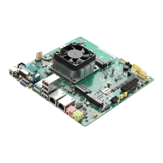
- Page 1 MIX-EHLD1...
- Page 2 E19509 First Edition December 2021 Copyright Notice This document is copyrighted, 2021. All rights are reserved. The original manufacturer reserves the right to make improvements to the products described in this manual at any time without notice. No part of this manual may be reproduced, copied, translated, or transmitted in any form or by any means without the prior written permission of the original manufacturer.
-
Page 3: Table Of Contents
Contents Chapter 1 Product overview Package contents ................. 1-1 Features ..................1-1 1.3 Specifications ................1-2 Chapter 2 Motherboard information Before you proceed ..............2-1 Motherboard layout ..............2-1 Screw size ..................2-4 2.3.1 Component side .............. 2-4 2.3.2 Solder side ..............2-5 Central Processing Unit (CPU) ........... - Page 4 3.4.1 System Agent (SA) Configuration ........3-8 3.4.2 PCH-IO Configuration ............. 3-8 Security menu ................3-8 3.5.1 Administrator Password ..........3-8 3.5.2 User Password ..............3-9 3.5.3 Secure Boot ..............3-9 Boot menu .................. 3-10 3.6.1 Boot Configuration ............3-11 3.6.2 Boot Option Priorities ............ 3-11 Save &...
-
Page 5: Chapter 1 Product Overview
Chapter 1 Product overview Package contents Check your industrial motherboard package for the following items. 1 x Industrial Motherboard 1 x SATA 6.0Gb/s cable 1 x SATA power cable 1 x I/O Shield If any of the above items is damaged or missing, contact your distributor or sales representative immediately. -
Page 6: Specifications
4-pin internal power connector Power Compliance Operating Temperature F~140 F (0 C~60 Operating Humidity 0%~90% RH, non-condensing Certificate CE & FCC Class A Form factor Mini-ITX 6.7”x 6.7” (170mm x 170mm) Weight 1.1 lb (0.5 Kg) (continued on the next page) MIX-EHLD1... - Page 7 Storage 1 x SATA 6Gb/s 1 x SATA power connector (5V / 12V @1A) 2 x USB 3.2 (Gen2) ports (at back panel) 4 x USB 2.0 ports (upper 2 ports by BOM Optional) Display I/O 1 x VGA, 1 x HDMI, 1 x LVDS (via CH7513; co-layout eDP) Audio I/O Line-out, AAFP LAN I/O...
- Page 8 Internal I/O 1 x AAFP follow ASUS pin out Connectors 1 x AT/ATX mode selection jumper 1 x PS_ON pin header 1 x CMOS jumper OS supported Windows 10 64-bit ® Accessories 1 x SATA cable 1 x SATA power cable 1 x I/O shield The specifications are subject to change without notice.
-
Page 9: Chapter 2 Motherboard Information
Chapter 2 Motherboard information Before you proceed Take note of the following precautions before you install motherboard components or change any motherboard settings. CAUTION! • Unplug the power cord from the wall socket before touching any component. • Before handling components, use a grounded wrist strap or touch a safely grounded object or a metal object, such as the power supply case, to avoid damaging them due to static electricity. - Page 10 17.0cm(6.7in) DC_PWR1 SYS_FAN1 EATX_PWR1 HDMI1 MIX-EHLD1 Place this side towards the rear of the chassis Intel ® Elkhart Lake USB3_CON1 USB2_CON2 BATT1 LAN1_CON1 2242 3042 3052 2280 BUZZ1 LAN2_CON1 256Mb BIOS COM1_V1 MIC-IN1 AAFP1 SIM_CARD1 Audio COM3 COM5 COM1 LINE-OUT1...
- Page 11 Page Connectors/Jumpers/Slots ATX Power connector (4-pin EATX_PWR1) 2-16 Battery connector (2-pin BATT1) 2-16 Chassis Fan header (4-pin SYS_FAN1) 2-17 Central Processing Unit (CPU) DDR4 SO-DIMM slots Panel power +3.3V/+5V jumper (3-pin PNL_PWR1) 2-11 Backlight Inverter Power connector (5-pin INV) 2-19 Inverter Voltage Selection jumper (3-pin BKL_PWR1) 2-10 Inverter Backlight Control Mode Selection jumper (3-pin CTL_SEL1)
-
Page 12: Screw Size
170.18 166.45 165.99 165.35 154.69 164.59 148.62 147.8 163.32 142.65 139.88 138.89 133.45 128.09 131.76 130.71 118.38 104.66 94.62 88.09 85.6 80.32 70.8 65.35 62.99 52.99 50.86 49.92 17.44 26.7 16.68 19.56 11.1 10.49 16.04 9.25 11.84 5.93 33.3(REF) MIX-EHLD1... -
Page 13: Solder Side
2.3.2 Solder side 170.18 165.1 165.1 130.59 113.59 113.24 103.24 97.97 73.82 62.59 33.02 10.16 Chapter 2: Motherboard information... -
Page 14: Central Processing Unit (Cpu)
Central Processing Unit (CPU) This motherboard comes with a Intel ElkHart Lake SoC Processor. ® Intel ® Elkhart Lake MIX-EHLD1... -
Page 15: System Memory
System memory This motherboard comes with two Double Data Rate 4 (DDR4) Small Outline Dual Inline Memory Modules (SO-DIMM) sockets. The figure illustrates the location of the DDR4 SO-DIMM sockets: Use the DIMM_A1 slot when inserting only one SO-DIMM. Installing a DIMM To install a DIMM To remove a DIMM Chapter 2: Motherboard information... -
Page 16: Jumpers
• You do not need to clear the RTC when the system hangs due to overclocking. For system failure due to overclocking, use the CPU Parameter Recall (C.P.R) feature. Shut down and reboot the system so the BIOS can automatically reset parameter settings to default values. MIX-EHLD1... - Page 17 Chassis Intrusion jumper (4-1 pin CHASSIS) This connector is for a chassis-mounted intrusion detection sensor or switch. Connect one end of the chassis intrusion sensor or switch cable to this connector. The chassis intrusion sensor or switch sends a high-level signal to this connector when a chassis component is removed or replaced.
- Page 18 AT/ATX Mode Selection jumper (3-pin AT_ATX) ATX_AT1 ATX mode AT mode (Default) Pins ATX mode (Default) AT mode Inverter Voltage Selection jumper (3-pin BKL_PWR) BKL_PWR1 +12V (Default) Setting Pins +12V +5V (Default) MIX-EHLD1 2-10...
- Page 19 Panel power +3.3V/+5V jumper (3-pin PNL_PWR1) PNL_PWR1 +3.3V (Default) COM1 RS-485/RS-422 termination jumpers (RSJ1~4) RS232 Terminator for (Default) RS485/RS422 Chapter 2: Motherboard information 2-11...
- Page 20 Inverter Backlight Control Mode Selection jumper (3-pin CTL_SEL1) CTL_SEL1 DC mode PWM mode (Default) Setting Pins DC Voltage Control PWM Control (Default) MIX-EHLD1 2-12...
- Page 21 COM1 Ring/+5V/+12V Selection jumper (6-pin COM1_V1) COM1_V1 Ring +12V (Default) Setting Pins +12V Ring (Default) Chapter 2: Motherboard information 2-13...
-
Page 22: Connectors
Ethernet port LED indications. LAN port LED indications ACT/LINK SPEED ACT/LINK LED SPEED LED Status Description Status Description Green 2.5 Gbps connection No link Orange 1 Gbps connection Green Linked 100 Mbps connection LAN port Blinking Data activity 10 Mbps connection MIX-EHLD1 2-14... - Page 23 Microphone port (pink). This port connects to a microphone. Line Out port (lime). This port connects to a headphone or a speaker. Chapter 2: Motherboard information 2-15...
-
Page 24: Internal Connectors
Find the proper orientation and push down firmly until the connector completely fit. EATX_PWR DC_IN DC_IN PIN 1 Battery connector (2-pin BATT1) This connector is for the lithium CMOS battery. BATT1 +BAT PIN 1 MIX-EHLD1 2-16... - Page 25 M.2 M Key slots (M2M1, M2B1) These slot allow you to install M.2 modules. M2M1 M2B1 • The M.2 SSD module is purchased separately. • The M.2 M Key slot supports type 2280 PCIe 3.0 x2 (Gen3) NVMe storage devices. Chassis Fan header (4-pin SYS_FAN1) Connect the fan cable to the fan header on the motherboard, ensuring that the black wire of each cable matches the ground pin of the header.
- Page 26 Signaling (LVDS) interface. PIN 40 SPD1 +BLVCC +BLVCC +BLVCC LVDS1_CLK- LVDS1_CLK+ VCON INV_ENABKL SPC1 LVDS0_CLK- LVDS0_CLK+ LVDS1 +V_PANEL +V_PANEL +V_PANEL LVDS1_D0- LVDS1_D0+ LVDS1_D1- LVDS1_D1+ LVDS1_D2- LVDS1_D2+ LVDS1_D3- LVDS1_D3+ LVDS0_D0- LVDS0_D0+ LVDS0_D1- LVDS0_D1+ LVDS0_D2- LVDS0_D2+ LVDS0_D3- LVDS0_D3+ PIN 1 MIX-EHLD1 2-18...
- Page 27 Backlight Inverter Power connector (5-pin INV) Connect the backlight inverter power cable to this connector. INV1 INV_ENABKL VCON +BLVCC2 PIN1 The backlight inverter power connector supports 1A current to the maximum. SATA Power header (4-pin SATA_PWR) This header is for the SATA power cable. The power cable plug is designed to fit this header in only one orientation.
- Page 28 I/O pin can be individually programmed to support various devices. DIO1 PIN 1 To configure the I/O pins in BIOS, go to the Advanced tab > Digital IO Port Configuration. See section 3.3.11 Digital IO Port Configuration for details. MIX-EHLD1 2-20...
- Page 29 10. System Panel header (10-1 pin F_PANEL) This header supports several chassis-mounted functions. F_PANEL1 (NC) O_RSTCON#_PR F_PWRBTN_N PLED- HDD_LED- PLED+ HDD_LED+ PIN 1 • System power LED (2-pin PWR_LED) This 2-pin header is for the system power LED. Connect the chassis power LED cable to this header.
- Page 30 COM3 COM5 COM1 COM4 PIN 1 COM6 The COM module is purchased separately. 12. Debug Card connector (DBG1) This connector allows connection to a Debug card. DEBUG1 PIN 1 ESPI_DB_IO0 ESPI_DB_IO1 ESPI_DB_IO2 ESPI_DB_IO3 ESPI_DB_CS_N ESPI_DB_RESET_N ESPI_DB_CLK +3VSUS MIX-EHLD1 2-22...
- Page 31 13. SIM Card slot (10-pin SIM_CARD1) This slot connects to a SIM card reader module. SIM_CARD1 14. Mini PCIe x1 slot (MINI_CARD1) Use this slot to connect Minicard readers. MINI_CARD1 • The Mini-card module is purchased separately. • MINI_CARD1 supports mSATA PCIE function. Chapter 2: Motherboard information 2-23...
- Page 32 We recommend that you connect a high-definition front panel audio module to this connector to avail of the motherboard’s high-definition audio capability. 16. Speaker Out connector (4-pin AMP_CON) The 4-pin connector is for the chassis-mounted speaker. AMP_CON1 PIN 1 The Speaker module is purchased separately. MIX-EHLD1 2-24...
- Page 33 17. USB 2.0 x 2 port header (USB2_HD1) USB2_HD1 PIN 1 Chapter 2: Motherboard information 2-25...
- Page 34 MIX-EHLD1 2-26...
-
Page 35: Chapter 3 Bios Setup
Chapter 3 BIOS Setup BIOS Setup Use the BIOS Setup to configure settings. The BIOS screens include navigation keys and help to guide you in using the BIOS Setup program. Entering BIOS Setup at startup To enter BIOS Setup at startup: Press <Delete>... -
Page 36: Main Menu
Case Open Warning [Disabled] Allows you to enable or disable case open warning function. Configuration options: [Disabled] [Enabled] [Clear] 3.3.1 CPU Configuration The items in this menu show CPU-related information the BIOS automatically MIX-EHLD1... -
Page 37: Trusted Computing
detects. The items shown in the submenu may be different depending on the type of CPU installed. Hyper-threading [Enabled] The Intel Hyper-Threading Technology allows a hyper-threading processor to appear as two logical processors to the operating system, allowing the operating system to schedule two threads or processes simultaneously. -
Page 38: Sata Configuration
None. 3.3.5 Hardware Monitor The items in this menu allow you to configure the smart fan. Smart Fan Configuration Fan Mode [Manual mode] Allows you to select the Fan mode. Configuration options: [Manual mode] [Thermal Cruise] [Speed Cruise] [Smart FAN IV] MIX-EHLD1... -
Page 39: Sio Configuration
Manual PWM [128] Allows you to select the PWM Value. Configuration options: 0~255 for 0%~100% 3.3.6 SIO Configuration The items in this menu allow you to configure Super IO settings. [*Active*] Serial Port 1 Use This device [Enabled] Allows you to enable or disable this logical device. Configuration options: [Enabled] [Disabled] The following two items appear only when you set Use this device to [Enabled]. -
Page 40: Pch-Fw Configuration
Me FW Image Re-Flash [Disabled] This item allows you to enable or disable Me FW Image Re-Flash function. Configuration options: [Disabled] [Enabled] FW Update [Enabled] This item allows you to enable or disable FW Update function. Configuration options: [Disabled] [Enabled] MIX-EHLD1... -
Page 41: Nvme Configuration
3.3.8 NVMe Configuration This menu displays the NVMe controller and Drive information of the connected devices. 3.3.9 Power Management Power Mode [ATX Type] Select power supply mode. Configuration options: [ATX Type] [AT Type] Ensure to power off the system before switching between ATX and AT type. Restore AC Power Loss [Last State] [Last State] The system goes into either off or on state, whatever the system... -
Page 42: System Agent (Sa) Configuration
From the Create New Password box, key in a password, then press <Enter>. Confirm the password when prompted. To change an administrator password: Select the Administrator Password item and press <Enter>. From the Enter Current Password box, key in the current password, then press <Enter>. MIX-EHLD1... -
Page 43: User Password
From the Create New Password box, key in a new password, then press <Enter>. Confirm the password when prompted. To clear the administrator password, follow the same steps as in changing an administrator password, but press <Enter> when prompted to create/confirm the password. -
Page 44: Boot Menu
Key Exchange Keys / Authorized Signatures / Forbidden Signatures / Authorized TimeStamps / OsRecovery Signatures This item allows you to enroll factory defaults or load certification from a file. Configuration options: [Update] [Append] Boot menu The Boot menu items allow you to change the system boot options. MIX-EHLD1 3-10... -
Page 45: Boot Configuration
3.6.1 Boot Configuration Quiet Boot [Enabled] This item enables/disables Quiet Boot. Configuration options: [Disabled] [Enabled] Network Stack [Disabled] This item allows you to disable or enable the UEFI network stack. Configuration options: [Disable] [Enable] 3.6.2 Boot Option Priorities Boot Option #1~#10 This item allows you to set the system boot order. - Page 46 MIX-EHLD1 3-12...
- Page 47 Appendix Notices Federal Communications Commission Statement This device complies with Part 15 of the FCC Rules. Operation is subject to the following two conditions: • This device may not cause harmful interference. • This device must accept any interference received including interference that may cause undesired operation.
- Page 48 ○ ○ ○ ○ 外部信號連接頭 × ○ ○ ○ ○ ○ 及線材 中央處理器與內 × ○ ○ ○ ○ ○ 存 本表格依據 SJ/T 11364 的規定編制。 ○: 表示該有害物質在該部件所有均質材料中的含量均在 GB/T 26572 規 定的限量要求以下。 ×: 表示該有害物質至少在該部件的某一均質材料中的含量超出 GB/T 26572 規定的限量要求,然該部件仍符合歐盟指令 2011/65/EU 的 規范。 備註:此產品所標示之環保使用期限,係指在一般正常使用狀況下。 MIX-EHLD1...