Table of Contents
Advertisement
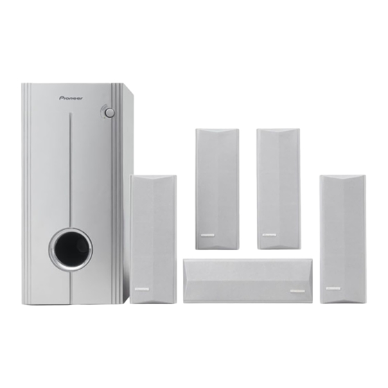
5.1ch SPEAKER SYSTEM(SATELLITE SPEAKER/POWERED SUBWOOFER)
S-HS01
THIS MANUAL IS APPLICABLE TO THE FOLLOWING MODEL(S) AND TYPE(S).
Model
Type
S-HS01
MLXTW/E
SDBXTW/E
CONTENTS
1. SAFETY INFORMATION ...................................... 2
2. EXPLODED VIEWS AND PARTS LIST ................ 3
3. SCHEMATIC DIAGRAM ........................................ 8
4. PCB CONNECTION DIAGRAM .......................... 10
5. PCB PARTS LIST ............................................... 13
6. ADJUSTMENT .................................................... 13
PIONEER CORPORATION
PIONEER ELECTRONICS (USA) INC. P.O. Box 1760, Long Beach, CA 90801-1760, U.S.A.
PIONEER EUROPE NV Haven 1087, Keetberglaan 1, 9120 Melsele, Belgium
PIONEER ELECTRONICS ASIACENTRE PTE. LTD. 253 Alexandra Road, #04-01, Singapore 159936
PIONEER CORPORATION 2001
Power Requirement
AC220 - 230V Ó
AC110V/120-127V/220V/240V Ó
4-1, Meguro 1-chome, Meguro-ku, Tokyo 153-8654, Japan
The voltage can be converted by
the following method.
With the voltage selector at the rear plate
7. GENERAL INFORMATION ................................ 14
7.1 DISASSEMBLY ........................................... 14
T - ZZV OCT. 2001 Printed in Japan
ORDER NO.
RRV2562
Advertisement
Table of Contents

Related Manuals for Pioneer S-HS01


Summary of Contents for Pioneer S-HS01
-
Page 1: Table Of Contents
PIONEER CORPORATION 4-1, Meguro 1-chome, Meguro-ku, Tokyo 153-8654, Japan PIONEER ELECTRONICS (USA) INC. P.O. Box 1760, Long Beach, CA 90801-1760, U.S.A. PIONEER EUROPE NV Haven 1087, Keetberglaan 1, 9120 Melsele, Belgium PIONEER ELECTRONICS ASIACENTRE PTE. LTD. 253 Alexandra Road, #04-01, Singapore 159936 PIONEER CORPORATION 2001 T –... -
Page 2: Safety Information
, a l w a y s c o n s u l t t h e c u r r e n t P I O N E E R Service Manual. A subscription to, or additional copies Also test with plug reversed of, PIONEER Service Manual may be obtained at a (Using AC adapter Earth nominal charge from PIONEER. -
Page 3: Exploded Views And Parts List
S-HS01 2. EXPLODED VIEWS AND PARTS LIST NOTES: Parts marked by "NSP" are generally unavailable because they are not in our Master Spare Parts List. mark found on some component parts indicates the importance of the safety factor of the part. - Page 4 S-HS01 2.2 SATELLITE SPEAKER...
- Page 5 S-HS01 SATELLITE SPEAKER PARTS LIST Mark No. Description Part No. Cabinet SNK2567 Grille SMG1746 Logo 24 SAM1491 Speaker Cord (Red) SDB1144 Speaker Cord (White) SDB1145 Packing SEC1571 Gasket SEC1573 Packing SEC1574 Input Terminal SKX1076 Stamped Model Label SME3269 Label Back...
- Page 6 S-HS01 2.3 POWERED SUBWOOFER...
- Page 7 TNC30P120FZK Screw H011009-322 Screw TNC35P140FZK Screw PRZ20P060FMC Screw PCZ30P080FZK (2) CONTRAST TABLE S-HS01/MLXTW/E and S-HS01/SDBXTW/E are constructed the same except for the following: Part No. Mark Symbol and Description Remarks S-HS01/MLXTW/E S-HS01/SDBXTW/E POWER ASSY APE0141C003 APE0141C002 AC Power Cord 2559-022G22...
-
Page 8: Schematic Diagram
S-HS01 3. SCHEMATIC DIAGRAM RB502 CN502 short C304 short CN401 RB401 CN401 RB401 330µF/16V RB301 RB502 CN301 CN502 330µF/16V JACK+VOL. ASSY (APE0127C021) LED ASSY (APE0127C031) A B C... - Page 9 S-HS01 Note : When ordering service parts, be sure to refer to "EXPLODED VIEWS and PARTS LIST" or "PCB PARTS LIST". : AUDIO SIGNAL ROUTE C516 M224 × 2 POWER ASSY (APE0141C003) (MLXTW/E type) RB902 RB903 RB901 AC : 220~230V Ó...
-
Page 10: Pcb Connection Diagram
S-HS01 4. PCB CONNECTION DIAGRAM NOTE FOR PCB DIAGRAMS : 1. Part numbers in PCB diagrams match those in the schematic 3. The parts mounted on this PCB include all necessary parts for diagrams. several destinations. 2. A comparison between the main parts of PCB and schematic For further information for respective destinations, be sure to diagrams is shown below. - Page 11 S-HS01 4.2 POWER ASSY POWER ASSY MLXTW/E type POWER SW AC IN AC IN SDBXTW/E type POWER SW...
- Page 12 S-HS01 4.3 MAIN ASSY SIDE A MAIN ASSY RB401 RB502 RB301 Q518 Q513 Q502 Q501 IC501 Q402 Q511 Q505 Q515 Q504 Q517 Q403 Q404 Q510 Q401 Q509 Q516 Q506 Q507 IC401 Q514 Q512 Q508...
-
Page 13: Pcb Parts List
Ex.2 When there are 3 effective digits (such as in high precision metal film resistors). 562 x 10 5.62k 5621 RN1/4PC 5 6 2 1 LIST OF WHOLE PCB ASSEMBLIES Part No. Remarks Mark Symbol and Description S-HS01/MLXTW/E S-HS01/SDBXTW/E LED ASSY APE0127C031 APE0127C031 JACK+VOL. ASSY APE0127C021 APE0127C021 MAIN ASSY APE0127C011 APE0127C011 POWER ASSY... -
Page 14: General Information
S-HS01 7. GENERAL INFORMATION 7.1 DISASSEMBLY 1. PRECAUTION FOR THE SPEAKER POWERED SUBWOOFER SATELLITE SPEAKER The speaker unit is attached to the grille by 4 internal screws. The woofer is attached to the baffle by 4 external screws. To detach it, first remove the rear plate cover by unfastening the To detach it, first remove the cabinet by unfastening the 4 screws of the cabinet rearside. -
Page 15: Panel Facilities And Specifications
S-HS01 8. PANEL FACILITIES AND SPECIFICATIONS 8.1 PANEL FACILITIES POWERED SUBWOOFER Front Panel 1 Power indicator (STANDBY/ON) Lights red when the power has been switched ON. Lights green when the speakers receive an audio signal. If the power is switched OFF only briefly, the indicator lights green when power is restored. - Page 16 S-HS01 8.2 SPECIFICATIONS Satellite speakers: Accessory Parts Enclosure ........ Closed Box, bookshelf type Speaker cords x 5 (5mx3, 10mx2) System ..........15 x 6 cm cone type RCA plug cord x 1 Nominal Impedance ............. 8 Ω Non-slip pads (5x3) Frequency Range ......