Table of Contents
Advertisement
Quick Links
Advertisement
Table of Contents

Related Manuals for Asus MAXIMUS V EXTREME


Summary of Contents for Asus MAXIMUS V EXTREME
- Page 1 MAXIMUS V EXTREME...
- Page 2 INCIDENTAL, OR CONSEQUENTIAL DAMAGES (INCLUDING DAMAGES FOR LOSS OF PROFITS, LOSS OF BUSINESS, LOSS OF USE OR DATA, INTERRUPTION OF BUSINESS AND THE LIKE), EVEN IF ASUS HAS BEEN ADVISED OF THE POSSIBILITY OF SUCH DAMAGES ARISING FROM ANY DEFECT OR ERROR IN THIS MANUAL OR PRODUCT.
-
Page 3: Table Of Contents
Product introduction Special features..................1-1 1.1.1 Product highlights................ 1-1 1.1.2 ROG Intelligent Performance & Overclocking features ....1-2 1.1.3 ASUS special features ..............1-4 1.1.4 ROG-rich bundled software............1-4 Motherboard overview ................1-6 1.2.1 Before you proceed ..............1-6 1.2.2 Motherboard layout ..............1-7 1.2.3... - Page 4 3.5.9 Network Stack ................3-36 Monitor menu ................... 3-37 Boot menu ....................3-41 Tools menu ....................3-43 3.8.1 ASUS EZ Flash 2 Utility ............3-43 ..............3-43 3.8.3 ASUS SPD Information ............. 3-44 3.8.4 GO Button File ................3-45 Exit menu ....................3-46 3.10...
- Page 5 4.3.7 Ai Charger+ ................4-17 4.3.8 USB Charger+ ................4-18 4.3.9 Probe II..................4-20 4.3.10 Sensor Recorder ............... 4-21 4.3.11 ASUS Update ................4-23 4.3.12 MyLogo2 ...................4-24 ..............4-25 4.3.14 ROG Connect................4-27 4.3.15 MemTweakIt ................4-29 Chapter 5: RAID support ..................
- Page 6 Intel 2012 Desktop responsiveness technologies ......... 7-1 7.1.1 Intel ® Smart Response Technology ..........7-3 7.1.2 Intel ® Rapid Start Technology ............7-4 ® 7.1.3 Intel Smart Connect Technology ..........7-10 Appendices Notices ........................A-1 ASUS contact information ..................A-5...
-
Page 7: Safety Information
Safety information Electrical safety • before relocating the system. • When adding or removing devices to or from the system, ensure that the power cables for the devices are unplugged before the signal cables are connected. If possible, disconnect all power cables from the existing system before you add a device. •... -
Page 8: About This Guide
Refer to the following sources for additional information and for product and software updates. ASUS websites The ASUS website provides updated information on ASUS hardware and software products. Refer to the ASUS contact information. Optional documentation that may have been added by your dealer. These documents are not part of the standard package. - Page 9 Conventions used in this guide To ensure that you perform certain tasks properly, take note of the following symbols used throughout this manual. DANGER/WARNING: Information to prevent injury to yourself when trying to complete a task. CAUTION: Information to prevent damage to the components when trying to complete a task IMPORTANT: Instructions that you MUST follow to complete a task.
- Page 10 ® Turbo Boost Technology 2.0 * The Intel ® Turbo Boost Technology 2.0 support depends on the CPU types. ** Refer to www.asus.com for Intel CPU support list Chipset ® Intel Z77 Express Chipset Memory 4 x DIMM, max. 32GB, DDR3 2800 (O.C.) / 2666(O.C.) / 2600(O.C.) / 2400 (O.C.) / 2200(O.C.) / 2133(O.C.) /...
- Page 11 ® Storage Intel Z77 Express Chipset with RAID 0, 1, 5, 10 support - 2 x SATA 6.0 Gb/s ports [red] for eSATA*** - 1 x mSATA 3.0 Gb/s slot on mPCIe Combo™ expansion card ® ® - Supports Intel Smart Response Technology, Intel Rapid Start Technology and Intel...
- Page 12 - USB 3.0 Boost - Fan Xpert2 - AI Charger+ - USB Charger+ - Disk Unlocker ASUS EZ DIY - ASUS CrashFree BIOS 3 - ASUS EZ Flash 2 - ASUS C.P.R. (CPU Parameter Recall) (continued on the next page)
- Page 13 Special Features ASUS Q-Design - ASUS Q-Code - ASUS Q-Shield - ASUS Q-Connector - ASUS Q-LED (CPU, DRAM, VGA, Boot Device LED) - ASUS Q-Slot - ASUS Q-DIMM Back I/O Ports 1 x Thunderbolt port 1 x Clear CMOS button 1 x ROG Connect On/Off button 4 x USB 2.0 (1 port for ROG Connect)
- Page 14 64Mb UEFI AMI BIOS, PnP, DMI2.0, WfM2.0, SM BIOS 2.5, ACPI2.0a Multi-language BIOS Software Drivers ® Kaspersky Anti-Virus DAEMON Tools Pro Standard ROG CPU-Z Mem TweakIt ASUS AI Suite II ASUS WebStorage ASUS Utilities Form Factor Extended ATX Form Factor, 12” x 10.7” (30.5cm x 27.2cm)
-
Page 15: Package Contents
1 x mPCIe Combo card with dual band Wi-Fi / Bluetooth module 2 x dual band Wi-Fi Ring Moving Antenna 1 x 2-port USB 2.0 and eSATA module 1 x 12-in-1 ROG cable label 1 x 2-in-1 ASUS Q-Connector kit Application DVD ROG motherboard support DVD Documentation User guide... -
Page 16: Installation Tools And Components
Installation tools and components 1 bag of screws PC chassis Power supply unit Intel LGA 1155 CPU Intel LGA 1155 compatible CPU Fan DDR3 DIMM SATA hard disk drive The tools and components in the table above are not included in the motherboard package. -
Page 17: Chapter 1: Product Introduction
* Intel 3rd generation Core™ processors support PCIe 3.0. SLI/CrossFire On-Demand This motherboard features a unique PCIe 3.0 bridge chip to support multi-GPU SLI/ CrossFireX graphics cards for an unrivaled gaming performance. With the Intel Z77 platform ASUS MAXIMUS V EXTREME... -
Page 18: Rog Intelligent Performance & Overclocking Features
® LucidLogix Virtu™ MVP LucidLogix ® Virtu™ MVP, with HyperFormance™ Technology, is designed for Intel ® processor graphics chip on Windows ® 7 and perfectly combines the performance of a discrete graphics card with fast computing iGPU (Integrated Graphics Processing Unit). The newly-designed Virtual VSync eliminates tearing artifacts allowing you to enjoy a smoother gaming experience. - Page 19 BIOS for the tweaked overclocking setting, and one saved BIOS from the previous version. VGA Hotwire Using the VGA Hotwire feature, you can plug two-wired cable onboard and solder two wires on the VGA’s voltage regulator to adjust the voltages accurately without risk. ASUS MAXIMUS V EXTREME...
-
Page 20: Asus Special Features
It also allows you to view POST codes and hardware 1.1.3 ASUS special features Wi-Fi GO! ASUS Wi-Fi GO! leads the way to a more enjoyable home entertainment. With ASUS Wi-Fi mobile device. Conveniently use and enjoy these ASUS Wi-Fi GO! functions: •... - Page 21 It gives you the current information and status of your CPU, motherboard, memory, and other main components. Get that ROG look of reporting your system’s current information with ROG CPU-Z. MemTweakIt ASUS MAXIMUS V EXTREME...
-
Page 22: Motherboard Overview
Motherboard overview 1.2.1 Before you proceed Take note of the following precautions before you install motherboard components or change any motherboard settings. • Unplug the power cord from the wall socket before touching any component. • Before handling components, use a grounded wrist strap or touch a safely grounded object or a metal object, such as the power supply case, to avoid damaging them due to static electricity. -
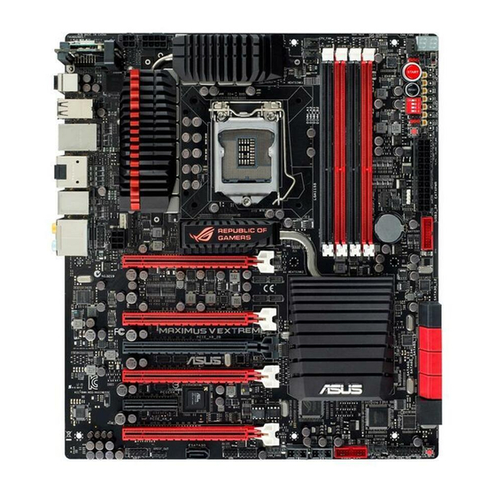
Page 23: Motherboard Layout
1.2.2 Motherboard layout Refer to 1.2.9 Internal connectors and 2.3.1 Rear I/O connection for more information about rear panel connectors and internal connectors. ASUS MAXIMUS V EXTREME... - Page 24 Layout contents Connectors/Jumpers/Buttons and switches/Slots Page 1. Power connectors (24-pin EATXPWR, 8-pin EATX12V, 4-pin EATX12V) 1-48 2. LGA1155 CPU Socket 3. CPU, chassis, and optional fan connectors (4-pin CPU_FAN, 4-pin 1-46 CPU_OPT, 4-pin OPT_FAN1-3, 4-pin CHA_FAN1-3) 4. DDR3 DIMM slots 1-10 5.
- Page 25 Contact your retailer immediately if the PnP cap is missing, or if you see any damage to the PnP cap/socket contacts/motherboard components. ASUS will shoulder the cost of repair only if the damage is shipment/ transit-related.
-
Page 26: System Memory
1.2.4 System memory The motherboard comes with four Double Data Rate 3 (DDR3) Dual Inline Memory Modules (DIMM) slots. A DDR3 module is notched differently from a DDR or DDR2 module. DO NOT install a DDR or DDR2 memory module to the DDR3 slot. 1-10 Chapter 1: Product introduction... - Page 27 To operate at the vendor-marked or at a higher frequency, refer to section 3.3 Extreme Tweaker menu for manual memory frequency adjustment. memory load (4 DIMMs) or overclocking condition. ASUS MAXIMUS V EXTREME 1-11...
- Page 28 DDR3 2800 MHz capability Vendors Part No. Size Chip Chip Timing Voltage DIMM socket Brand support G.skill F3-2800CL11Q-16G 16GB (4x4GB) 11-13-13-35 1.65 • • BZHD DDR3 2666 MHz capability Vendors Part No. Size Chip Chip Timing Voltage DIMM socket Brand support G.skill F3-2666CL10Q-16GBZHD...
- Page 29 KINGSTON KHX2133C11D3K4/16G 16GB 11-12- 1.65 • • • X(XMP) (4x4GB) 11-30 KINGSTON KHX2133C11D3T1K2/1 16GB 9-9-9- • • • 6GX(XMP) (2x8GB) OCZ3XTEP2133C9LV4 GK 7-7-7- 1.65 • • Patriot PVV34G2133C9K(XMP) 9-11- 1.66 • • • (2x2GB) 9-27 ASUS MAXIMUS V EXTREME 1-13...
- Page 30 DDR3 2000 MHz capability Vendors Part No. Size Chip Chip NO. Timing Voltage DIMM socket Brand A-DATA AX3U2000GB2G9B(XMP) 9-11- 1.55~1.75 • • • 9-27 A-DATA AX3U2000GC4G9B(XMP) 9-11- 1.55~1.75 • • • 9-27 AEXEA AXA3ES4GK2000LG28V 1.65 • • • (XMP) (2x2GB) Apacer 78.AAGD5.9KD(XMP) 9-9-9-27...
- Page 31 TXD34096M1866H C9K- Hynix H5TC2G 9-11-9- 1.65 • • • L(XMP) 83BFRH9A DDR3 1800 MHz capability Vendors Part No. Size Chip Chip Timing Voltage DIMM socket Brand support G.SKILL F3-14400CL9D-4GBRL(XMP) 4GB (2x2GB) 9-9-9-24 • • • ASUS MAXIMUS V EXTREME 1-15...
- Page 32 DDR3 1600 MHz capability Vendors Part No. Size Chip Chip NO. Timing Voltage DIMM socket Brand A-DATA AM2U16BC2P1 3CCD-1509A • • • DATA A-DATA AM2U16BC4P2 3CCD-1509A • • • DATA A-DATA AX3U1600GC4G9 (XMP) 1.55 • • • ~1.75 A-DATA AX3U1600PC4G8 (XMP) 8-8-8-24 1.55 •...
- Page 33 • 12GX (XMP) (3x4GB) KINGSTON KHX1600C9D3K3/6GX 1.65 • • • (XMP) (3x2GB) KINGSTON KHX1600C9D3K3/6GX 1.65 • • • (XMP) (3x2GB) KINGSTON KHX1600C9D3K6/ 24GB 1.65 • • • 24GX (XMP) (6x4GB) (continued on the next page) ASUS MAXIMUS V EXTREME 1-17...
- Page 34 DDR3 1600 MHz capability Vendors Part No. Size Chip Chip NO. Timing Voltage DIMM socket Brand Kingston KHX1600C9D3K8/32GX 32GB 9-9-9-27 1.65 • • • (XMP) (8x4GB) KINGSTON KHX1600C9D3LK2/4GX 1.35 • • • (XMP) (2x2GB) KINGSTON KHX1600C9D3P1K2/8G • • • (2x4GB) KINGSTON KHX1600C9D3T1BK3/12 12GB...
- Page 35 ACTICA ACT4GHU64B8H1333H Hynix H5TQ2G8 • • • 3AFR ACTICA ACT4GHU72D8H1333H Hynix H5TQ2G83 • • • AFR(ECC) A-DATA AD63I1B0823EV A-DATA 3CCA-1509A • • • A-DATA AD63I1C1624EV A-DATA 3CCA-1509A • • • (continued on the next page) ASUS MAXIMUS V EXTREME 1-19...
- Page 36 DDR 1333 MHz capability Vendors Part No. Size Chip Brand Chip NO. Timing Voltage DIMM socket A-DATA AXDU1333GC2G9(XMP) 9-9-9-24 1.25~1.35 • • • A-DATA SU3U1333W8G9(XMP) ELPIDA J4208BASE- • • • DJ-F Apacer 78.A1GC6.9L1 Apacer AM5D5808F • • • EQSBG Apacer 78.B1GDE.9L10C Apacer AM5D5908C...
- Page 37 • • D J-F KINGSTON KVR1333D3N9K2/4G KINGSTON D1288JEMFP • • • (2x2GB) GD9U KINGSTON KVR1333D3S8N9/2G Micron IFD77 • • • D9LGK KINGTIGER F10DA2T1680 KING KTG1333PS • • • TIGER 1208NST-C9 (continued on the next page) ASUS MAXIMUS V EXTREME 1-21...
- Page 38 DDR 1333 MHz capability Vendors Part No. Size Chip Brand Chip NO. Timing Voltage DIMM socket support KING KTG2G1333PG3 • • • TIGER Mach MXD3U133316GQ 16GB • • • Xtreme (4x4GB) Mach MXD3V13332GS Mach C2S46D3 • • • Xtreme Xtreme 0-D313 MICRON MT16KTF51264AZ-1G6M1...
- Page 39 (574206) Transcend TS256MLK64V3NL Hynix H5TQ2G83CF • • • RH9C Transcend TS512MLK64V3N Micron IED27 D9L • • • (585538 ) Transcend TS512MLK64V3N Micron D9LGK • • • (574831) Transcend TS512MLK64V3NL Hynix H5TQ2G83C • • • FRH9C ASUS MAXIMUS V EXTREME 1-23...
- Page 40 ASUS exclusively provides hyper DIMM support function. • Hyper DIMM support is subject to the physical characteristics of individual CPUs. Load the X.M.P. settings in the BIOS for the hyper DIMM support. • Visit the ASUS website for the latest QVL. 1-24 Chapter 1: Product introduction...
-
Page 41: Expansion Slots
Slot No. Slot Description PCIe 3.0/2.0 x16/x8_1 slot PCIe 3.0/2.0 x16_2A slot PCIe 3.0/2.0 x8_2B slot PCIe 3.0/2.0 x8_3 slot PCIe 2.0/1.1 x4_1 slot PCIe 3.0/2.0 x8_4 slot ASUS MAXIMUS V EXTREME 1-25... - Page 42 PCIe Express 3.0 operating mode SLI/ 3-WAY SLI/ 4-WAY SLI/ Single VGA CrossFireX CrossFireX PCIe 3.0/2.0_x16/x8_1 x16 (Native) x8 (Native) x8 (Native) x8 (Native) – – PCIe 3.0/2.0_x16_2A – – – PCIe 3.0/2.0_x8_2B x8 (Native) – – PCIe 3.0/2.0_x8_3 – –...
- Page 43 XHCI (USB 3.0) shared – – – – – – – Asmedia USB 3.0 shared – – – – – – – Controller Asmedia SATA 6G – – – shared – – – – Storage Controller ASUS MAXIMUS V EXTREME 1-27...
-
Page 44: Onboard Buttons And Switches
1.2.6 Onboard buttons and switches open-case system. This is ideal for overclockers and gamers who continually change settings to enhance system performance. Power-on button The motherboard comes with a power-on button that allows you to power up or wake up the system. The button also lights up when the system is plugged to a power source indicating that you should shut down the system and unplug the power cable before removing or installing any motherboard component. - Page 45 Press the GO button before POST to enable MemOK! or press it to quickly load the BIOS Switch button The motherboard comes with two BIOS. Press the BIOS button to switch BIOS and load different BIOS settings. The nearby BIOS LEDs indicate the BIOS you are using. ASUS MAXIMUS V EXTREME 1-29...
- Page 46 Slow Mode switch Slow Mode switch allows your system to provide better overclocking margins when using the LN2 cooling system. When enabled, the Slow Mode switch prevents the system from crashing, slows down the CPU, and the system’s tuner will make the adjustments.
-
Page 47: Jumpers
The ROG Connect Switch header allows connection of a 2-pin cable switch (purchased separately) for users to quickly enable/disable the OC Key feature without using the ROG Connect On/Off button on the rear I/O port. ASUS MAXIMUS V EXTREME 1-31... -
Page 48: Onboard Leds
1.2.8 Onboard LEDs Hard Disk LED The hard disk LED is designed to indicate the hard disk activity. It blinks when data is being written into or read from the hard disk drive. The LED does not light up when there is no hard disk drive connected to the motherboard or when the hard disk drive does not function. - Page 49 ON, in sleep mode, or in soft-off mode. This is a reminder that you should shut down the system and unplug the power cable before removing or plugging in any motherboard component. The illustration below shows the location of the onboard power-on button. ASUS MAXIMUS V EXTREME 1-33...
- Page 50 BIOS LED The BIOS LEDs help indicate the BIOS activity. Press the BIOS button to switch between BIOS1 and BIOS2 and the LED lights up when the corresponding BIOS is in use. Q-Code LEDs The Q-Code LED design provides you with a 2-digit error code that displays the system status.
- Page 51 19 – 1C 2B – 2F Reserved for ASL (see ASL Status Codes section below) Memory Installed 32 – 36 37 – 3A 3B – 3E DXE IPL is started (continued on the next page) ASUS MAXIMUS V EXTREME 1-35...
- Page 52 Q-Code table Code Description 50 – 53 speed Memory not installed Invalid CPU type or Speed CPU mismatch CPU self test failed or possible CPU cache error CPU micro-code is not found or micro-code update is failed Not used Power on. Reset type detection (soft/hard). Microcode loading 0C –...
- Page 53 Reserved for future AMI error codes Recovery condition triggered by user (Forced recovery) Recovery process started F5 – F7 Reserved for future AMI progress codes Recovery PPI is not available (continued on the next page) ASUS MAXIMUS V EXTREME 1-37...
- Page 54 Q-Code table Code Description Recovery capsule is not found Invalid recovery capsule FB – FF Reserved for future AMI error codes DXE Core is started Installation of the PCH Runtime Services 63 – 67 6B – 6F 73 – 77 7A –...
- Page 55 Runtime Set Virtual Address MAP Begin Runtime Set Virtual Address MAP End System Reset USB hot plug PCI bus hot plug Clean-up of NVRAM B8– BF Reserved for future AMI codes (continued on the next page) ASUS MAXIMUS V EXTREME 1-39...
- Page 56 Q-Code table Code Description Some of the Architectural Protocols are not available PCI resource allocation error. Out of Resources No Space for Legacy Option ROM No Console Output Devices are found No Console Input Devices are found Invalid password Error loading Boot Option (LoadImage returned error) Boot Option is failed (StartImage returned error) Flash update is failed Reset protocol is not available...
-
Page 57: Internal Connectors
You must install Windows ® XP Service Pack 3 or later versions before using Serial ATA hard disk drives. The Serial ATA RAID feature is available only if you are using Windows ® XP SP3 or later versions. ASUS MAXIMUS V EXTREME 1-41... - Page 58 ® Intel These connectors connect to Serial ATA 3.0 Gb/s hard disk drives and optical disc drives via Serial ATA 3.0 Gb/s signal cables. If you installed Serial ATA hard disk drives, you can create a RAID 0, 1, 5, and 10 ®...
- Page 59 XP Service Pack 3 or later versions before using Serial ATA hard disk drives. Subzero Sense connector the motherboard temperature via BIOS, OC Key or TurboV EVO without purchasing expensive multimeters. The K probe cable is purchased separately. ASUS MAXIMUS V EXTREME 1-43...
- Page 60 This connector is for the additional USB 3.0 ports, and complies with the USB 3.0 cable is available from your system chassis, with this USB 3.0 connector, you can have a front panel USB 3.0 solution. ® Due to Intel limitations, USB3_34 connector ports run at USB 3.0 speed rate under Windows ®...
- Page 61 48 MBps connection speed. Never connect a 1394 cable to the USB connectors. Doing so will damage the motherboard! then install the Q-Connector (USB) to the USB connector onboard if your chassis supports front panel USB ports. ASUS MAXIMUS V EXTREME 1-45...
- Page 62 CPU, chassis, and optional fan connectors Connect the fan cables to the fan connectors on the motherboard, ensuring that the black wire of each cable matches the ground pin of the connector. the system may damage the motherboard components. These are not jumpers! Do not place jumper caps on the fan connectors! •...
- Page 63 HD Audio or legacy AC`97 audio standard. Connect one end of the front panel audio I/O module cable to this connector. connector, set the Front Panel Type item in the BIOS setup to [HD] or [AC97]. ASUS MAXIMUS V EXTREME 1-47...
- Page 64 1000W power or above to ensure the system stability. • If you are uncertain about the minimum power supply requirement for your system, refer to the Recommended Power Supply Wattage Calculator at http://support.asus. com/PowerSupplyCalculator/PSCalculator.aspx?SLanguage=en-us for details. 1-48 Chapter 1: Product introduction...
- Page 65 Pressing the power switch for more than four seconds while the system is ON turns the system OFF. This 2-pin connector is for the chassis-mounted reset button for system reboot without turning off the system power. ASUS MAXIMUS V EXTREME 1-49...
- Page 66 These connectors provide additional power to PCIe_x16 slots and back IO ports. Connect a 6-pin power cable to EZ_PLUG_1 when installing multiple display cards provide a stable power supply to the back IO ports. These connectors are for temperature monitoring. Connect the thermal sensor cables to these connectors and place the other ends to the devices which you want to monitor the temperature.
- Page 67 VGA card for voltage adjustment. The 2-pin cable is purchased separately. Connects to the OC Key device that allows quick on-screen overclocking adjustments. Refer to section 2.3.2 OC Key device installation for details. ASUS MAXIMUS V EXTREME 1-51...
-
Page 68: Probeit
1.2.10 ProbeIt The ROG ProbeIt allows you to detect your system’s current voltage and OC settings. Use a multimeter to measure the ProbeIt points even during overclocking. See the illustration below to locate the respective ProbeIt points. Using ProbeIt You may connect the multitester to the motherboard as shown on Figure 1, or use the ProbeIt cable to connect to the motherboard as shown on Figure 2. -
Page 69: Chapter 2: Basic Installation
The diagrams in this section are for reference only. The motherboard layout may vary with models, but the installation steps are the same for all models. Install the ASUS Q-Shield to the chassis rear I/O panel. ASUS MAXIMUS V EXTREME... - Page 70 Place the motherboard into the chassis, ensuring that its rear I/O ports are aligned to the chassis’ rear I/O panel. Chapter 2: Getting started...
- Page 71 Place nine screws into the holes indicated by circles to secure the motherboard to the chassis. DO NOT overtighten the screws! Doing so can damage the motherboard. ASUS MAXIMUS V EXTREME...
-
Page 72: Cpu Installation
2.1.2 CPU installation The LGA1156 CPU is not compatible with the LGA1155 socket. DO NOT install an LGA1156 CPU on the LGA1155 socket. Chapter 2: Getting started... -
Page 73: Cpu Heatsink And Fan Assembly Installation
2.1.3 CPU heatsink and fan assembly installation Apply the Thermal Interface Material to the CPU heatsink and CPU before you install the heatsink and fan if necessary. To install the CPU heatsink and fan assembly ASUS MAXIMUS V EXTREME... - Page 74 To uninstall the CPU heatsink and fan assembly Chapter 2: Getting started...
-
Page 75: Dimm Installation
2.1.4 DIMM installation To remove a DIMM ASUS MAXIMUS V EXTREME... -
Page 76: Atx Power Connection
2.1.5 ATX Power connection Chapter 2: Getting started... -
Page 77: Sata Device Connection
2.1.6 SATA device connection ASUS MAXIMUS V EXTREME... -
Page 78: Front I/O Connector
2.1.7 Front I/O Connector To install ASUS Q-Connector To install USB 2.0 connector To install front panel audio connector AAFP USB 2.0 To install USB 3.0 connector USB 3.0 2-10 Chapter 2: Getting started... -
Page 79: Expansion Card Installation
2.1.8 Expansion Card installation To install PCIe x16 cards To install PCIe x1 cards ASUS MAXIMUS V EXTREME 2-11... -
Page 80: Mpcie Combo Installation
2.1.9 mPCIe Combo installation The mPCIe Combo is a mini card that allows you to add an mPCIe module and an mSATA module into your motherboard. • The mPCIe and mSATA modules are purchased separately. • The Wi-Fi module is already installed to the mPCIe Combo card, and will only be available in certain motherboard models. - Page 81 DO NOT overtighten the screws to prevent damage to the mPCIe Wi-Fi module or mPCIe Combo. Be sure to install the Bluetooth driver before installing the Wi-Fi GO! software. Remove the screw beside the 26-pin connector. ASUS MAXIMUS V EXTREME 2-13...
- Page 82 Locate the mPCIe_Combo connector on the motherboard. Align and insert the mPCIe Combo on the connector. • Insert the mPCIe Combo with caution to prevent damage to the module, or the mCPIe_Combo connector pins, or the motherboard. Secure the mPCIe Combo in place with the screws removed in step 4. 2-14 Chapter 2: Getting started...
- Page 83 The Wi-Fi antenna and its cables are purchased separately. Re-attach the bolt on the connector. antenna connector washer bolt I/O Shield Connect the opposite end of the Wi-Fi antenna connector to the pins located on the mPCIe Wi-Fi card. ASUS MAXIMUS V EXTREME 2-15...
- Page 84 Installing the mSATA module To install the mSATA module: Unlock the mSATA clip. Insert the mSATA card into the MSATA slot. Lock the mSATA clip. 2-16 Chapter 2: Getting started...
- Page 85 Locate the mPCIe_Combo connector on the motherboard. Align and insert the mPCIe Combo on the connector. • Insert the mPCIe with caution to prevent damage to the module, or the mPCIe_Combo connector pins, or the motherboard. ASUS MAXIMUS V EXTREME 2-17...
- Page 86 Secure the mPCIe Combo in place with the screw removed in step 4. 2-18 Chapter 2: Getting started...
-
Page 87: Bios Update Utility
• Updating BIOS may have risks. If the BIOS program is damaged during the process and results to the system’s failure to boot up, please contact your local ASUS Service Center. ASUS MAXIMUS V EXTREME... - Page 88 6. ROG Connect button 7. USB 2.0 ports 1-3 8. USB 2.0 port 4, also ROG Connect port 9. ASMedia USB 3.0 ports, support ASUS USB 3.0 Boost UASP Mode 10. HDMI port 11. DisplayPort 12. Intel USB 3.0 ports, support ASUS USB 3.0 Boost Turbo Mode 13.
- Page 89 Front Speaker Out Pink Mic In Mic In Mic In Mic In Orange – – Center/Subwoofer Center/Subwoofer Black – Rear Speaker Out Rear Speaker Out Rear Speaker Out 2.3.2 Audio I/O connections Audio I/O ports ASUS MAXIMUS V EXTREME 2-21...
- Page 90 Connect to Headphone and Mic Connect to Stereo Speakers Connect to 2.1 channel Speakers 2-22 Chapter 2: Getting started...
- Page 91 Connect to 4.1 channel Speakers Connect to 5.1 channel Speakers ASUS MAXIMUS V EXTREME 2-23...
- Page 92 Connect to 7.1 channel Speakers 2-24 Chapter 2: Getting started...
- Page 93 OC Key port hole to secure the cable in place. Plug the OC Key cable into the onboard connector labeled OC KEY. Plug the other end of the OC Key cable to the OC Key device. ASUS MAXIMUS V EXTREME 2-25...