Table of Contents
Advertisement
Quick Links
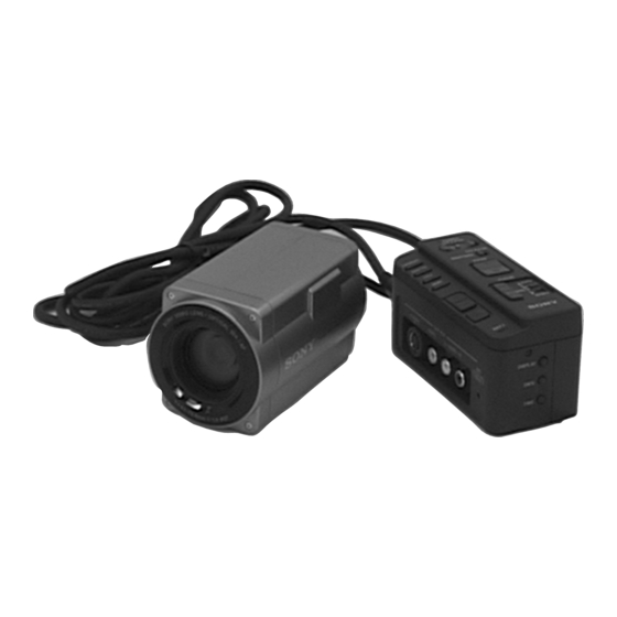
CVX-V18NS/V18NSP
SERVICE MANUAL
Ver 1.1 2000. 02
NTSC model: CVX-V18NS
PAL model : CVX-V18NSP
MICROFILM
Printed wiring boards and schematic diagrams are not mentioned
because mounted boards are replaced to repair this model.
SPECIFICATIONS
US Model
Canadian Model
AEP Model
CVX-V18NSP
COLOR VIDEO CAMERA
CVX-18NS
Advertisement
Table of Contents

Related Manuals for Sony CVX-V18NS


Summary of Contents for Sony CVX-V18NS
- Page 1 US Model Canadian Model Ver 1.1 2000. 02 CVX-18NS AEP Model CVX-V18NSP NTSC model: CVX-V18NS PAL model : CVX-V18NSP Printed wiring boards and schematic diagrams are not mentioned because mounted boards are replaced to repair this model. SPECIFICATIONS COLOR VIDEO CAMERA...
-
Page 2: Service Note
SERVICE NOTE • NOTE FOR REPAIR When remove a connector, don’t pull at wire of connector. Be in danger of the snapping of a wire. Make sure that the flat cable and flexible board are not cracked of bent at the terminal. Do not insert the cable insufficiently nor crookedly. -
Page 3: Table Of Contents
TABLE OF CONTENTS Section Title Page Section Title Page SERVICE NOTE ..............2 D Page Table ..............5-7 E Page Table ..............5-7 F Page Table ..............5-7 GENERAL 5-3. Electrical Adjustments ........... 5-8 Y Out Level Adjustment ..........5-8 C Out Level Adjustment .......... -
Page 4: General
CVX-V18NS/V18NSP SECTION 1 This section is extracted from CVX- GENERAL V18NS/V18NSP instruction manual. - Page 10 1-7 E...
-
Page 11: Disassembly
CVX-V18NS/V18NSP SECTION 2 DISASSEMBLY • This set can be disassembled in the order shown below. Main Unit Cabinet (Upper) Block Ass’y (Page 2-2) Cabinet (Rear) Block Ass’y (Page 2-2) CN-116 Board DT-106 Board VA-108 Board VW-1 Board Battery Terminal Board... -
Page 12: Cabinet (Upper) Block Ass'y
Note: Follow the disassembly procedure in the numerical order given. 2-1. CABINET (UPPER) BLOCK ASS’Y 2-3. VW-1 BOARD, BATTERY TERMINAL BOARD 5 Cabinet (upper) block ass’y 1 Five screws 2 Terminal board retainer 3 Two screws 4 Two claws (M2) 3 VW-1 board 2 Screw (M2) -
Page 13: Cabinet (R) Ass'y
2-5. CN-116 BOARD 2-7. CABINET (R) ASS’Y 2 Screw (M2) 3 CN-116 board 1 Screw (M2) - 1 1 1 Flat cable (FFC-274) (CN990) 2 Two screws 3 Four screws 4 Cabinet (R) ass’y (M2) 2-6. CABINT (F/B) ASS’Y 2-8. IF-73 BOARD 3 Four screws 1 Flexible board (M2) -
Page 14: Cabinet (L) Ass'y
2-9. CABINET (L) ASS’Y 2-11. CONNECTION CORD 6 Screw 1 Screw 2 Screw 4 Cabinet (L) ass’y (M2) (M2) (M2) 7 Connection cord 3 Screw (BB bracket) (M2) 2 Two connectors 4 Lug (CN301, 501) a r d I F - a r d I F - 5 Two screws... -
Page 15: Board
2-13. SE-93 BOARD 2-15. LENS DEVICE 3 SE-93 board 1 Remove the lens device in the direction of the arrow. 1 Flat cable (FFC-219) (CN050) - 9 3 2 Three screws a r d (M2) I F - a r d I F - 2-14. -
Page 16: Circuit Boards Location
2-17. CIRCUIT BOARDS LOCATION SW-328 (CONTROL SWITCH) CN-116 CAMERA CABLE CONNECTOR DT-106 MIC IN, CONTROL SWITCH VW-1 (VIDEO WALKMAN CONNECTOR) VA-108 VIDEO/AUDIO OUTPUT, CONTROL SWITCH VC-211 CCD IMAGER, CAMERA Y/C PROCESS, CAMERA CONTROL, MODE CONTROL SE-93 (STEADY SHOT SENSOR) IR-34 (IR LIGHT) IF-73 (IR MOTOR DRIVE) -
Page 17: Block Diagrams
CVX-V18NS/V18NSP SECTION 3 BLOCK DIAGRAMS 3-1. OVERALL BLOCK DIAGRAM ZOOM LENS UNIT VC-211 BOARD ZOOM IRIS LENS VA-108 BOARD METER IC101 IC001 V1-V4,VSHT TIMING H1,H2,RG IMAGER GENERATOR IC821 CN-116 BOARD IC201 M903 M902 M901 CCD OUT IC102 CAMERA CABLE ZOOM... -
Page 18: Camera Block Diagram
CVX-V18NS/V18NSP 3-2. CAMERA BLOCK DIAGRAM VC-211 BOARD (1/3) IC102 S/H. AGC. A/D CONVERTER IC201 IC001 CAMERA Y/C PROCESS. PBL K CCD IMAGER FOCUS/ZOOM MOTOR CONTROL XSHP Q001 XSHD CCD OUT CCD OUT REC Y RF BUFFER CLPDM UNREG VIHDO 3.2V... -
Page 19: Camera Control (1/2) Block Diagram
CVX-V18NS/V18NSP 3-3. CAMERA CONTROL (1/2) BLOCK DIAGRAM VC-211 BOARD (2/3) SE-93 BOARD CN050 CN601 3.2V IC602 IC050 SE050 CAMERA CONTROL SENSOR AMP 3.2V AVDD AVRH SE051 PITCH AD VST C RESET XTAL X401 YAW AD 20MHz EXTAL XSYS RST XSYS RST... -
Page 20: Camera Control (2/2) Block Diagram
CVX-V18NS/V18NSP 3-4. CAMERA CONTROL (2/2) BLOCK DIAGRAM IF-73 BOARD VC-211 BOARD (3/3) IC1803 VISCA CONTROL IC702 IC701 MODE CONTROL INITIAL RESET IC804 BACKUP VCC REGULATOR 20MHz OUT CN1802 CN703 X701 UNREG 20MHz VOUT UNREG E3.2V E3.2V 20MHz IN D701 3.2V 3.2V... -
Page 21: Video Out, Audio Block Diagram
CVX-V18NS/V18NSP 3-5. VIDEO OUT, AUDIO BLOCK DIAGRAM VA-108 BOARD CN-116 BOARD CN990 CN883 UNREG CN991 UNREG TO CAMERA BLOCK IC821 UNREG VC-211 BOARD CN501 UNREG Y/C MIX VIDEO AMP (SEE PAGE 3-8) J821 TO CAMERA BLOCK S-Y_OUT S-Y_IN S-Y_OUT VC-211 BOARD CN301... -
Page 22: Power (Main Unit) Block Diagram
CVX-V18NS/V18NSP 3-6. POWER (MAIN UNIT) BLOCK DIAGRAM CN-116 BOARD VA-108 BOARD BATTERY Q882 TERMINAL F881 SWITCH CN883 CN881 CN990 1.25A BATT (+) CN991 UNREG UNREG UNREG UNREG TO POWER (CAMERA) UNREG IC883 VC-211 BOARD CN501 BATT SW (-) 5.5V DETECT... -
Page 23: Power (Camera) Block Diagram
CVX-V18NS/V18NSP 3-7. POWER (CAMERA) BLOCK DIAGRAM CN704 VC-211 BOARD UNREG TO LANC JIG 3.2V IF-73 BOARD IC1804 IC1803 IC701 IC702 IC102 IC202 CN501 3.2V REG VISCA COM RESET HI-COM S/H AGC A/D CHARACTER GENERATOR SW_UNREG CN703 CN1802 CN1803 UNREG TO POWER (MAIN UNIT) UNREG 3.2V... -
Page 24: Schematic Diagrams
CVX-V18NS/V18NSP SECTION 4 SCHEMATIC DIAGRAMS 4-1. FRAME (1/2) SCHEMATIC DIAGRAM CN-116 BOARD M901 CONNECTION CN991 CORD (SEE PAGE 4-4) MOTOR CN401 23P TEMP TEMP CN1802 30P CN703 30P UNREG UNREG FC_RST SENSE PLA/GLASS KEY_AD6 KEY_AD6 FC_A KEY_AD5 KEY_AD5 FC_B KEY_AD4... -
Page 25: Frame (2/2) Schematic Diagram
CVX-V18NS/V18NSP 4-2. FRAME (2/2) SCHEMATIC DIAGRAM VIDEO WALKMAN CONNECTOR POWER NIGHTSHOT VW-1 BOARD SW-328 BOARD ZOOM FOCUS FFC-275 INFINITY MANU CN-116 BOARD AUTO NEAR CN883 14P CN990 14P FFC-272 UNREG UNREG CN991 12P VA-108 BOARD UNREG UNREG UNREG EXPOSURE UNREG_GND... -
Page 26: Adjustments
CVX-V18NS/V18NSP SECTION 5 ADJUSTMENTS NTSC model: CVX-V18NS PAL model : CVX-V18NSP 5-1. PREPARATIONS BEFORE ADJUSTMENT 5-1-1. List of Service Tools • Oscilloscope • Regulated power supply • Vectorscope • Frequency counter • Color monitor • Digital voltmeter Ref. No. Name... -
Page 27: Preparations
5-1-2. Preparations Note 1: For details of how remove the cabinet and boards, refer Pattern box to “2. DISASSEMBLY”. 1) Connect the equipment for adjustments according to Fig. 5-1-3. 2) Connect the adjusting remote commander to the CN704 on the VC-211 board via CPC jig (J-643-193-0A). Front side of the lens L = About 40 cm Fig. -
Page 28: Precautions
5-1-3. Precautions 1. Setting the Switch Unless otherwise specified, set the switches as follows and per- form adjustments. 1. POWER switch (Main unit) ........ ON 2. NIGHT SHOT switch (Main unit) ...... OFF 3. FOCUS switch (Main unit) ......... AUTO 2. -
Page 29: Adjusting Remote Commander
5-1-4. Adjusting Remote Commander • Changing the address The address increases when the FF ()) button is pressed, The adjusting remote commander is used for changing the calcu- and decreases when the REW (0) button is pressed. There lation coefficient in signal processing, EVR data, etc. The adjust- are altogether 256 addresses, from 00 to FF. -
Page 30: Data Processing
5-1-5. Data Processing The calculation of the DDS display and adjusting remote com- mander display data (hexadecimal notation) are required for ob- taining the adjustment data of some adjustment items. In this case, after converting the hexadecimal notation to decimal notation, calculate and convert the result to hexadecimal notation, and use it as the adjustment data. -
Page 31: Initialization Of D, E, F
5-2. INITIALIZATION OF D, E, F PAGE DATA 2. Modification of D, E, F Page Data If D, E, F PAGE data has been initialized, change the data of the 1. Initializing D, E, F Page Data “Fixed data-2” address shown in the following tables by manual Note 1: If “Initializing D, E, F Page Data”... - Page 32 3. D Page Table 5. F Page Table Note 1: Fixed data-1: Initialized Data. (Refer to “1. Initializing Note 1: Fixed data-1: Initialized Data. (Refer to “1. Initializing D, E, F Page Data”) D, E, F Page Data”) Fixed data-2: Modified Data. (Refer to “2. Modification Fixed data-2: Modified Data.
-
Page 33: Electrical Adjustments
5-3. ELECTRICAL ADJUSTMENTS 2. C OUT Level Adjustment Set the Chroma signal output level 1. Y OUT Level Adjustment Subject Not required Set the Y signal output level Measurement Point VIDEO output terminal (75 Ω terminated) Subject Not required Measurement Point VIDEO output terminal Measuring Instrument Oscilloscope... -
Page 34: 28 Mhz Origin Oscillation Adjustment
3. 28 MHz Origin Oscillation Adjustment Set the frequency of the clock for synchronization. If deviated, the synchronization will be disrupted and the color will become inconsistent. Subject Not required Pin @¡ of CN703 on VC-211 Measurement Point board Measuring Instrument Frequency counter Adjustment Page Adjustment Address... -
Page 35: Camera System Adjustment
5-4. CAMERA SYSTEM ADJUSTMENT 2. G-CAM Flip Adjustment Set the color reproduction conditions to optimum. Before perform the camera system adjustments, check that the Subject Color bar chart standard picture specified value of frame “Y OUT Level Adjustment”, “C OUT Level Adjustment” and “28MHz Origin Oscillation Adjustment”... -
Page 36: G-Cam Version Adjustment
3. G-CAM Version Adjustment Confirm the G-CAM version, and enter the data according to the version. Subject Not required Measurement Point Displayed data of page: 2, address: 04 Measuring Instrument on adjusting remote commander Adjustment Address Page: E, Address: 0A, 0B Page: F, Address: 8D, 8E Adjusting method: 1) Select page: 0, address: 01, and set data: 01. -
Page 37: Hall Adjustment
4. HALL Adjustment 19) Select page: F, address: 30, change data and adjusting the DDS For detecting the position of lens iris, adjust the HALL AMP gain displayed data to “80”. and offset. 20) Press the PAUSE button of the adjusting remote commander. 21) Select page: 2, address: 01, and set data: 03, and press the Subject Not required... -
Page 38: Flange Back Adjustment (Using The Mini-Pattern Box)
5. Flange Back Adjustment Adjusting method: (Using the mini-pattern box) 1) Install the camera so that the distance between its lens surface The inner focus lens flange back adjustment is carried out auto- and mini-pattern box is less than 3 cm. matically. -
Page 39: Flange Back Adjustment (Using The Flange Back Adjustment Chart And The Subject More Than 500 M Away)
6. Flange Back Adjustment 6-2. Flange Back Adjustment (2) (Using the flange back adjustment chart and the Perform this adjustment after performing “Flange Back Adjust- subject more than 500 m away) ment (1)” The inner focus lens flange back adjustment is carried out auto- matically. -
Page 40: Flange Back Check
7. Flange Back Check Subject Siemens star chart (2.0 m from the front of the lens) (Luminance: approx. 200 lux) Measurement Point Check operation on TV monitor Measuring Instrument Switch setting: 1) NIGHT SHOT switch ............OFF Checking method: 1) Place the Siemens star 2.0 m from the front of the lens. 2) To open the IRIS, decrease the luminous intensity to the Si- emens star up to a point before noise appear on the image. -
Page 41: Picture Frame Setting
8. Picture Frame Setting Check on the oscilloscope Subject Color bar chart standard picture 1. Horizontal period frame (About 40 cm from the front of lens) Measurement Point VIDEO output terminal Measuring Instrument Oscilloscope and TV monitor Specified Value A = B, C = D, t = 0 ± 0.1 msec Setting method: 1) Adjust the camera direction and zoom, and set to the specified position. -
Page 42: Color Reproduction Adjustment
9. Color Reproduction Adjustment For NTSC model Adjust the color separation matrix coefficient so that proper color reproduction is produced. Subject Color bar chart standard picture frame Measurement Point VIDEO output terminal Measuring Instrument Vectorscope Adjustment Page Adjustment Address 34, 36, F5, F6 Specified Value All color luminance points should settle within each color... -
Page 43: Iris In/Out Adjustment
10. IRIS IN/OUT Adjustment Processing after Completing Adjustments: Measure the light level and write into EEPROM for indoor/out- 1) Select page: 2, address: 01, set data: 00, and press the PAUSE door identification in auto white balance. button of the adjusting remote commander. If it is not correct, white balance will be incorrect from standard 2) Select page: 2, address: 40, set data: 00, and press the PAUSE position. -
Page 44: Auto White Balance Standard Data Input
11. Auto White Balance Standard Data Input 12. Auto White Balance Adjustment Adjust to the proper auto white balance output data. Subject Clear chart If it is not correct, auto white balance and color reproducibility (Color bar chart standard picture will be poor. -
Page 45: White Balance Check
13. White Balance Check Subject Clear chart (Color bar chart standard picture frame) Filter Filter C14 for color temperature correction ND filter 1.0 and 0.3 Measurement Point VIDEO output terminal Measuring Instrument Vectorscope Specified Value Fig. 5-4-6. (A) to (C) Fig. -
Page 46: Repair Parts List
CVX-V18NS/V18NSP SECTION 6 REPAIR PARTS LIST 6-1. EXPLODED VIEWS NOTE: • Items marked “*” are not stocked since they are • -XX and -X mean standardized parts, so they may seldom required for routine service. Some delay have some difference from the original one. -
Page 47: Camera Head Section-1
A-7073-991-A SE-93 BOARD, COMPLETE 1-790-256-11 CABLE, FLEXIBLE FLAT (FFC-264) * 67 3-055-149-01 BRACKET, BB X-3949-609-1 CABINET (L) ASSY X-3949-608-1 CABINET (R) ASSY (CVX-V18NS) 3-958-286-01 SHEET METAL, TRIPOD X-3949-635-1 CABINET (R) ASSY (CVX-V18NSP) 3-968-729-21 SCREW (M2), LOCK ACE, P2 1-790-767-11 CABLE, FLEXIBLE FLAT (FFC-280) -
Page 48: Camera Head Section-2
2-623-756-21 SCREW (B1.7X5), P 1-790-255-11 CABLE, FLEXIBLE FLAT (FFC-262) 3-713-791-51 SCREW (M1.7X3.5), TAPPING, P2 IC001 A-7030-865-A CCD BLOCK ASSY (CVX-V18NS) (Note 1) 3-978-981-11 ADAPTOR (FK), CCD FITTING IC001 A-7030-871-A CCD BLOCK ASSY (CVX-V18NSP) (Note 1) 1-758-084-21 FILTER BLOCK, OPTICAL (OFB-04-11) -
Page 49: Electrical Parts List
CN883 1-779-331-11 CONNECTOR, FFC/FPC 14P CN1805 1-766-337-21 CONNECTOR, FFC/FPC 7P CN884 1-779-329-11 CONNECTOR, FFC/FPC 10P A-7073-992-A IR-34 BOARD, COMPLETE A-7094-503-A VC-211 BOARD, COMPLETE (CVX-V18NS) ********************* A-7094-504-A VC-211 BOARD, COMPLETE (CVX-V18NSP) < CONNECTOR > ********************** CN090 1-573-347-11 CONNECTOR, FFC/FPC (ZIF) 7P <... - Page 50 8-848-722-01 DEVICE, LENS LSV-600A (SOC) 1-758-084-21 FILTER BLOCK, OPTICAL (OFB-04-11) 1-672-209-11 FP-64 FLEXIBL BOARD 1-790-255-11 CABLE, FLEXIBLE FLAT (FFC-262) IC001 A-7030-865-A CCD BLOCK ASSY (CVX-V18NS) (Note 1) IC001 A-7030-871-A CCD BLOCK ASSY (CVX-V18NSP) (Note 1) M901 1-763-206-11 MOTOR (IR USE)
- Page 51 FOR CAMERA COLOR REPRODUCTION ADJUSTMENT Take a copy of CAMERA COLOR For NTSC model REPRODUCTION FRAME with a clear sheet for use. CVX-V18NS For PAL model CVX-V18NSP...
- Page 52 CVX-V18NS/V18NSP Sony Corporation 99D0511-1 9-974-162-11 Personal VIDEO Products Company Printed in Japan © 1999. 4 – 74 – Published by Safety & Service Engineering Dept.
- Page 53 CVX-V18NS/V18NSP US Model Canadian Model SERVICE MANUAL CVX-18NS AEP Model CVX-V18NSP 2000. 02 CORRECTION-1 File this correction with the service manual (99-027) CORRECTION OF PARTS CODE : Points corrected portion. 5-1. PREPARATIONS BEFORE ADJUSTMENT 5-1-1. List of Service Tools Ref. No.