Panasonic RX-D10 Service Manual
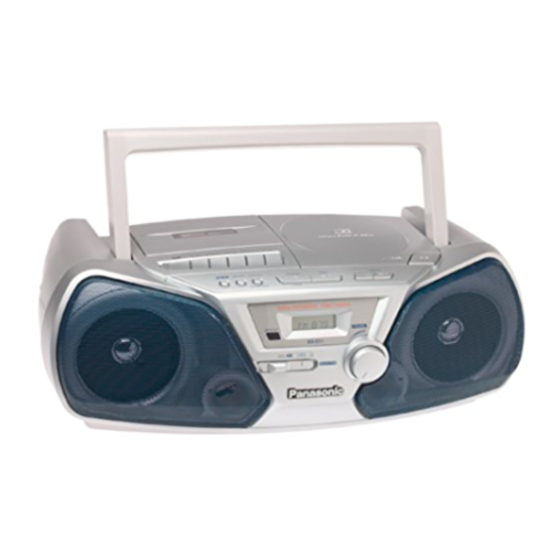
Portable stereo cd system
Hide thumbs
Also See for RX-D10:
- Operating instructions manual (16 pages) ,
- Operating instructions manual (8 pages) ,
- Operating instructions manual (9 pages)

Related Manuals for Panasonic RX-D10


Summary of Contents for Panasonic RX-D10
- Page 1 Order No. MD0105085C1 Portable Stereo CD System RX-D10 Color (A) ... Blue Type PC ... Canada Tape Deck: SG20 Mechanism Series Traverse Deck: RAE0152Z-1C Traverse Deck Series SPECIFICATIONS...
- Page 2 RADIO Frequency Range 520-1710 kHz (10 kHz steps) 87.9-107.9 MHz (200 kHz steps) 87.5-108.0 MHz (100 kHz steps) Intermediate Frequency 450 kHz 10.7 MHz Sensitivity 40 dB/m/50 mW 22.5 dB/50 mW TAPE RECORDER Track System 4 track, 2 channel, stereo Recording system AC bias Erasing system...
- Page 3 Output Phones 3.5 mm stereo (32 Dimensions (W x H x D) 460 x 168 x 268 mm (18-1/8” x 6-5/8” x 10-9/ 16”) Weight About 3.2 kg without batteries Power consumption in standby mode Notes: 1. Weights and dimensions shown are approximate. 2.
- Page 4 Stops during a performance. The function of this circuitry is to prevent circuitry damage if, for example, the positive and negative speaker connection wires are “shorted”, or if speaker systems with an impedance less than the indicated rated impedance of the amplifier are used.
- Page 5 Approximately 9.5 hrs of CD Recording. (EIAJ) The battery service life is measured according to the conditions set forth by EIAJ. (Electronic Industries Association of Japan). As the battery service life varies with the method of operation and environmental conditions, use these values as reference.
- Page 7 5. Precaution of Laser Diode Caution: This unit utilizes a class 1 laser. Invisible laser radiation is emitted from the optical pickup lens. When the unit is turned on: 1. Do not look directly into the pickup lens. 2. Do not use optical instruments to look at the pickup lens. 3.
- Page 8 6. Controls...
- Page 10 7. Self-Diagnostic Functions 7.1. Setting of the Self-Diagnostic Mode 1. Switch the SELECTOR to CD and set to TAPE STOP state. (CD PLAY STOP) 2. Press the /CLEAR for the first two seconds and followed by the FAST FORWARD keys for another two seconds without releasing the /CLEAR key, it shall enter into the Self-Diagnostic mode.
- Page 11 7.3. Display Content Abnormal Items Error Method of detection Display CLOSE SW abnormal Detect error during closing operation and memorised it as an error. REST SW abnormal Under normal operation (Self-Diagnostic Mode inclusive), this error occurs when the REST SW ON is not detected within the specified time (5000 ms) and shall be memorised.
-
Page 12: Table Of Contents
1. This section describes procedures for checking the operation of the major printed circuit boards and replacing the main components. 2. For reassembly after operation checks or replacement, reverse the respective procedures. Special reassembly procedures are described only when required. 3. - Page 16 Step 4: Remove the wire from CP601. Step 5: Take out the speaker box cover on both sides. Step 6: Remove the cable connection CP301.
-
Page 17: Checking For The Cd Servo P.c.b
8.1.2. Checking for CD Servo P.C.B. - Page 18 Step 9: Remove the FFC wire from CN702...
-
Page 19: Main Component Replacement Procedures
8.2. Main Component Replacement Procedures 8.2.1. Replacement of the Traverse Deck... - Page 20 Step 2: Desolder the 4 legs of the 2 motors and pull out the Servo P.C.B. Step 3: Widen the 3 bosses with a flat screwdriver and pull out the 3 pins. Then remove the Traverse Deck.
- Page 21 Note : Insert a short pin into the flexible cable for traverse unit.
- Page 22 Step 4: Remove the flexible cable CN701.
-
Page 23: Installation Of The Cd Servo P.c.b. After Replacement
Removal of the flexible cable. Push the top of the connector in the direction of the arrow 1, and the pull out the flexible cable in the direction of the arrow 2. 8.2.2. Installation of the CD Servo P.C.B. after Replacement Step 1 Connect the FFC board. - Page 24 Note : Before installing the CD servo P.C.B., move the optical pickup towards the outer edge from the marking (black triangle). [Otherwise, the detect switch (S701) mounted on the CD servo P.C.B. may be damaged.] 9. Schematic Diagram (All schematic diagrams may be modified at any time with the development of new technology.) Notes: S701...
- Page 25 100 mA (FM & AM) 180 mA (FM REC & AM REC) 150 mA (TAPE Playback) 240 mA (CD) 290 mA (CD REC) Volume maximum : 300 mA (FM & AM) 380 mA (FM REC & AM REC) 440 mA (TAPE Playback) 590 mA (CD) 690 mA (CD REC) The voltage value and waveforms are the reference voltage of this unit measured...
- Page 27 10. Printed Circuit Board 11. Wiring Connection Diagram...
- Page 29 12. Troubleshooting Guide...
- Page 31 13. Measurements and Adjustments 13.1. Tuner Section READ CAREFULLY BEFORE ATTEMPTING ALIGNMENT 1. Set volume control to maximum. 2. Set power source voltage to 9V. 3. Output of signal generator should be no higher than necessary to obtain an output reading. AM-RF ALIGNMENT Signal Generator or Sweep Radio Dial...
- Page 32 Signal Generator or Sweep Generator Radio Dial Indicator (Electronic Adjustment Remarks Setting Voltmeter or (Shown in Connections Frequency Oscilloscope) Fig.1) Fashion a loop of 87.9 kHz Point of non- Headphone Jack (32 [*1] L4 ( FM Adjust for several turns of wire interference.(on ) Fabricate the plug as ANT Coil)
- Page 33 3. Measure and make sure that the output is within the standard value. 4. Insert the CrO2 tape (QZZCRX). 5. Repeat steps 2 and 3. Bias voltage for Deck (Standard value) : 9.0 ± 2.0mV BIAS FREQUENCY ADJUSTMENT (DECK) 1. Set the unit to TUNER mode. 2.
- Page 34 13.2. CD Section Alignment is unneccessary for CD section of this unit. 13.2.1. Alignment Points...
- Page 35 14. Type Illustrations of ICs, Transistors & Diodes 15. Terminal Functions of ICs IC701 (AN8839NSBE2) Servo Amplifier...
- Page 36 Mark Function Tracking signal input 1 Tracking signal input 2 Power Supply Focus signal input terminal 1 Focus signal input terminal 2 APC amp input APC amp output RF summing output RFIN Detector’s input CSBRT Capacitor for OFTR connection Capacitor for HPF amp connection BDO output (“H”: drop out)
- Page 37 Mark Function BCLK N.C. LRCK N.C. SRDATA N.C. DVDD1 Power supply input (for digital circuit) DVSS1 Gnd (for digitial circuit) Digital audio interface signal output (Latches data at first transition) MCLK Microprocessor command clock signal input MDATA Microprocessor command data signal input Microprocessor command load signal...
- Page 38 Traverse drive output...
- Page 39 Mark Function Spindle motor ON signal output (“L”: ON) Spindle motor drive signal output (forced mode output) Spindle motor drive signal output (servo error signal output) KICK N.C. Tracking drive output Focus drive output VREF D/A (drive) output (TVD,ECS, TRD, FOD, FBAL, TBAL) reference voltage input FBAL...
- Page 40 IREF Reference current input Mark Function DSL bias terminal DSLF I/O DSL loop filter terminal PLLF I/O PLL loop filter terminal VCOF I/O VCO loop filter terminal AVDD2 Power supply input (for analog circuit) AVSS2 Gnd (for analog circuit) N.C. N.C.
- Page 41 Mark Function RSEL RF signal polarity assignment input (at “H” level: RSEL = “H”) (at “L” level: RSEL = “L”) IOVDD 5V Supply PSEL Test terminal (connected to Gnd) MSEL SMCK oscillating frequency designation input (“L”: 4.2336MHz, “H”: 8.4672MHz) SSEL SUBQ output mode select (“H”: Q-code buffer mode) IC703 (AN8739SBE2) Focus Coil/Tracking Coil/Traverse Motor/Spindle Motor...
- Page 42 Mark Function Motor driver (3) forward- action output Motor driver (4) reverse- action output Motor driver (4) forward- action output N.C. PGND2 Ground connectin (2) for driver PVCC2 Power supply (2) for driver N.C. Power supply terminal VREF Reference voltage input Motor driver (4) input Motor driver (3) input RSTIN...
- Page 43 Mark Function FREF_IN Micro-P beatproof reference freq input N.C. SQCK CD subcode data clock PCNT Power control output SUBQ CD subcode block clock input 23 REMOTE_IN I Remote controller input BLKCK CD subcode block clock input N.C. N.C. RESET System reset input XOSC IN XOSC INPUT XOSC...
- Page 44 Mark Function No connection PLL CE PLL chip enable output PLL CLK PLL clock output PLL data output DATA TONE 1 Tone 1 control output N.C. N.C. N.C. N.C. N.C. 59~72 SEG... LCD segment output Power supply VREF A/D converter reference voltage AVSS 76~79 C OM3~COM0 I...
- Page 45 farads(pF); Farads. Resistance values are in ohms, unless specified otherwise, 1K=1,000(ohms). The marking (RTL) indicates that the Retention Time is limited for this item. After the discontinuation of this assembly in production, the item will continue to be available for a specific period of time. The retention period of availability is dependant on the type of assembly, and in accordance with the lows govening part and product retention.
- Page 46 Ref. No. Part No. Part Name & Description Remarks CASSETTE DECK RDV0021 MAIN BELT ‘D’ RMB0109-1 BRAKE SPRING RML0116 BRAKE RBR2CY009 ERASE HEAD RDG0057-1 IDLER GEAR RDG0059 FF RELAY GEAR RDK0005-1 CAM GEAR RDV0006-1 RF BELT RHW16009 CAPSTAN WASHER RMA0109 BACK PLATE RMB0043-1 ROD OPERATION SPRING...
- Page 47 Ref. No. Part No. Part Name & Description Remarks RHD20049 AZIMUT SCREW RMA1080 HEAD PANEL RMR0149 HEAD BASE RXR0004 TAKE UP REEL ASSY RXR0005 SUPPLY REEL ASSY XTN2+6J BACK PLATE SCREW RHD26002 MOTOR SCREW XTN2+8F R/P SCREW RMG0102-1 MOTOR RUB. CUSHION RFM179ZA DC MOTOR ASS’Y RMA0108...
- Page 48 Ref. No. Part No. Part Name & Description Remarks CABINET AND CHASSIS REEX0085 CD FFC WIRE REX0836 HEAD WIRE REXX0219 SPEAKER WIRE REXX0220 MOTOR WIRE REXX0222 LEAFSW WIRE RAS10P30-G SPEAKER RFKGXD10EB-A FRONT CABINET ASS’Y RKWX0143-Q LCD PANEL RGKX0054-S CD LID RGUX0344-S CD EJECT BUTTON RGUX0345-S...
- Page 49 Ref. No. Part No. Part Name & Description Remarks TRAVERSE DECK RAE0152Z-1C TRAVERSE 358-1 SHGD113-1 FLOATING CUSHION 358-2 SNSD38 TRV MOTOR ASS’Y SCREW 358-3 RAF0150A-1 OPTICAL PICKUP 358-4 RDG0247 DRIVE GEAR 358-5 RDG0248 INTERMEDIATE GEAR 358-6 RXQ0339 TRAVERSE MOTOR ASS’Y 358-7 RXQ0304-1 PLATE NUT ASS’Y...
- Page 50 Ref. No. Part No. Part Name & Description Remarks Q101 KTC3199GRTA TRANSISTOR Q103 KTC3199GRTA TRANSISTOR Q201 KTC3199GRTA TRANSISTOR Q203 KTC3199GRTA TRANSISTOR Q301 KTA1046 TRANSISTOR Q302 KTC3199BLTA TRANSISTOR Q303 KTA12710YTA TRANSISTOR Q304 KTC3199BLTA TRANSISTOR Q305 KTA12710YTA TRANSISTOR Q306 KTC3199BLTA TRANSISTOR Q308 KRA102MTA TRANSISTOR Q701...
- Page 51 Ref. No. Part No. Part Name & Description Remarks SW601 EVQPAD05R SW REV SKIP SW602 EVQPAD05R SW FWD SKIP SW603 EVQPAD05R SW PLAY/PAUSE SW604 EVQPAD05R SW FM MODE/CLEAR SW605 EVQPAD05R SW PLAY MODE SW606 EVQPAD05R SW MEMORY SW607 EVQPAD05R SW TONE/XBS SW802 RSH1A012-U SW CD LEAF...
- Page 52 Ref. No. Part No. Part Name & Description Remarks RSXZ456KZ02 CERAMIC RESONATOR RSXD7M20C01 CRYSTAL OSCILLATOR X701 RSXZ16M9M01T CERAMIC OSCILLATOR X802 RSXZ4M19Z01T MICON CRYSTAL FUSES F501 XBA1C12NB5H FUSE F502 XBA1C12NB5H FUSE FUSE HOLDERS FH501 RJF0028 FUSE HOLDER FH502 RJF0028 FUSE HOLDER FH503 RJF0028 FUSE HOLDER...
- Page 53 Ref. No. Part No. Part Name & Description Remarks ERDS2TJ222T 2.2K 1/4W ERDS2TJ223T 22K 1/4W ERDS2TJ472T 4.7K 1/4W ERDS2TJ102T 1K 1/4W ERDS2TJ223T 22K 1/4W ERDS2TJ103T 10K 1/4W ERDS2TJ223T 22K 1/4W ERDS2TJ103T 10K 1/4W ERDS2TJ332T 3.3K 1/4W ERDS2TJ223T 22K 1/4W ERDS2TJ103T 10K 1/4W ERDS2TJ472T 4.7K 1/4W...
- Page 54 Ref. No. Part No. Part Name & Description Remarks R320 ERDS2TJ472T 4.7K 1/4W R321 ERDS2TJ151T 150 1/4W R322 ERDS2TJ151T 150 1/4W R323 ERDS2TJ332T 3.3K 1/4W R324 ERDS2TJ333T 33K 1/4W R325 ERDS2TJ123T 12K 1/4W R326 ERDS2TJ223T 22K 1/4W R327 ERDS2TJ223T 22K 1/4W R328 ERDS2TJ333T 33K 1/4W...
- Page 55 Ref. No. Part No. Part Name & Description Remarks R801 ERDS2TJ473T 47K 1/4W R802 ERDS2TJ473T 47K 1/4W R803 ERDS2TJ473T 47K 1/4W R804 ERDS2TJ103T 10K 1/4W R807 ERDS2TJ104T 100K 1/4W R808 ERDS2TJ224T 220K 1/4W R813 ERDS2TJ333T 33K 1/4W R814 ERDS2TJ104T 100K 1/4W R815 ERDS2TJ104T 100K 1/4W...
- Page 56 Ref. No. Part No. Part Name & Description Remarks R1104 ERDS2TJ682T 6.8K 1/4W R1105 ERDS2TJ222T 2.2K 1/4W R1106 ERDS2TJ680T 68 1/4W R1201 ERDS2TJ183T 18K 1/4W R1202 ERDS2TJ272T 2.7K 1/4W R1203 ERDS2TJ224T 220K 1/4W R1204 ERDS2TJ682T 6.8K 1/4W R1205 ERDS2TJ222T 2.2K 1/4W R1206 ERDS2TJ680T 68 1/4W...
- Page 57 Ref. No. Part No. Part Name & Description Remarks ECBT1H102KB5 1000P 50V ECBT1H102KB5 1000P 50V RCE1HM010BP 1 50V ECBT1H102KB5 1000P 50V ECBT1H102KB5 1000P 50V ECBT1H102KB5 1000P 50V ECBT1H331KB5 330 50V ECBT1H331KB5 330 50V ECBT1H102KB5 1000P 50V C109 ECA1HM0R1B 0.1 50V C110 RCE1HMR22BP 22 50V...
- Page 58 Ref. No. Part No. Part Name & Description Remarks C333 ECBT1C103MS5 0.01 16V C335 ECBT1C103MS5 0.01 16V C341 ECBT1H102KB5 1000P 50V C342 ECBT1H102KB5 1000P 50V C501 ECKR1H103ZF5 0.01 50V C502 ECKR1H103ZF5 0.01 50V C503 ECKR1H103ZF5 0.01 50V C504 ECKR1H103ZF5 0.01 50V C701 ECEA0JKA330I 33 6.3V...
- Page 59 Ref. No. Part No. Part Name & Description Remarks C753 ECUV1H471KBM 470P 50V C754 ECUV1H471KBM 470P 50V C802 ECBT1H102KB5 1000P 50V C804 ECFR1C104MR 0.1 16V C805 RCE1HM010BP 1 50V C817 ECBT1H102KB5 1000P 50V C818 ECBT1H102KB5 1000P 50V C819 ECBT1H102KB5 1000P 50V C820 ECBT1H820KB5 82 50V...
- Page 60 Ref. No. Part No. Part Name & Description Remarks RJ701 ERJ6GEY0R00V 0 1/10W RJ702 ERJ8GEY0R00V 0 1/8W RJ703 ERJ8GEY0R00V 0 1/8W RJ704 ERJ8GEY0R00V 0 1/8W RJ707 ERJ8GEY0R00V 0 1/8W RJ708 ERJ8GEY0R00V 0 1/8W RJ709 ERJ8GEY0R00V 0 1/8W RJ710 ERJ8GEY0R00V 0 1/8W RJ712 ERJ8GEY0R00V 0 1/8W...
- Page 61 A2 : O/I BOOK Printed in Singapore M010500001FLE/H/C/D/J 2001 Matsushita Electronics (S) Pte. Ltd. All rights reserved. Unauthorized copying and distribution is a violation of law.
- Page 62 S81252SGY-Z TA2008AN (24P) AN8839NSBE2 (28P) S1NB20-4101 MN662790RSC (80P) TA8227P PST9123T AN8739SBE2 (28P) M38224M6H104 (100P) LC72131D (22P) BA3313L KTA1046 2SB709STX KRA102MTA KTA12710YTA RVTDTC143EST KRC104MTA KV1360NTM KTC3199BLTA KTC3199GRTA KV1520ATS2 2SA1515STPQ RVD1SS133TA RB441QT-77 MTZJ5R1BTA MTZJ6R2CTA MTZJ7R5CTA MTZJ18BTA...
- Page 63 MAIN / TUNER P.C.B. (REPX0196K) TELESCOPIC ANTENNA J214 J215 J341 J340 J166 J338 C314 R312 C315 R316 Q308 R320 R315 R340 J160 R839 D308 J150 J324 J149 J146 J320 J144 C802 J418 C804 J317 R865 J135 J211 J133 J171 C847 R113 R818 R140...
- Page 64 PHONES J343 C225 J342 J341 J339 J340 JK301 J173 J338 C314 R312 C315 IC303 L1001 R316 Q308 C317 R320 TP20 R315 C116 R340 J162 D305 J160 CP303 TP21 C330 R125 2 3 4 J327 J326 R225 J157 R1201 J346 C217 C1201 J347 J156...
- Page 65 PANEL (1) P.C.B. (REPX0196K) W307 R601 SW603 SW602 SW601 R602 R603 BAND CD PLAY/PAUSE FWD SKIP REV SKIP PANEL (2) P.C.B. (REPX0196K) SW604 SW607 SW606 SW605 FM MODE STOP/CLEAR R605 PLAY/TUNE R604 MEMORY MODE PROGRAM SPEAKER TERMINAL P.C.B. (REPX0196K) W302...
- Page 67 CD SERVO P.C.B (REP2880A-N) (RF) TP20 X701 TJ701 TP23 C717 R714 TP19 TP21 C716 TP29 C721 R709 C744 TP24 C722 R712 TP18 C723 C724 R742 C725 TP25 IC701 TP26 TP27 C731 C753 TP22 C754 C711 J702 C718 C712 IC702 C713 J712 R705 C747...
- Page 68 SCHEMATIC DIAGRAM-1 : + B Line : CD Signal Line CD SERVO CIRCUIT OPTICAL PICKUP PLAY CIRCUIT 0.6V C701 6.3V33 R701 C703 0.5us. 0.2V/DIV 6.3V100 Q701 2.7V Q701 3.2V LASER DIODE ((2.3V)) 2SB709STX C704 CN701 LASER POWER DRIVE 0.9V ((2V)) LD GND C713 (GUARD)
- Page 69 SCHEMATIC DIAGRAM-2 : + B Line : CD Signal Line R717 C727 50V1 C725 1000P R721 C726 1000P R718 C728 50V1 C743 PLAY 2.2V CN702 Lch OUT 1KHz, 0dB A.GND C731 C753 Rch OUT 470P 6.3V220 +3.3V D.GND C730 C732 C733 C754 LD SW...
- Page 70 SCHEMATIC DIAGRAM-3 : FM Signal Line : AM Signal Line : +B Line MAIN(TUNER) CIRCUIT : AM OSC Signal Line : FM/AM Signal Line R2 10K M0.022 K1000P KV1520ATS2 100K 50V1 RL02B131-T R8 100K R9 100K K1000P 3.3K KV1360NTM 50V1 D2 KV1360NTM K1000P RLD4Y45-F...
- Page 71 SCHEMATIC DIAGRAM-4 : Playback Signal Line : +B Signal Line : Main Signal Line : FM/AM Signal Line : CD Signal Line : Rec Signal Line MAIN CIRCUIT BU5V R813 L819 2.2uH R814 R815 [4.5V] 4.1V 100K C823 100K ((4.4V)) C822 10V100 1000P...
- Page 72 nal Line R113 Q805 KTA1272YTA Z801 0.4V CD_LCH ((3.4V))..LID CLOSE R140 SWITCH RSL5257-G ((3.4V))..LID OPEN [0V] 3.3V CD_RCH R240 Q805 R114 0.3V R214 TUNER_SEL ((2.8V))..LID CLOSE 5.6K 5.6K ((4.7V))..LID OPEN [0V] C341 1000P 0.3V 3.3V ((3.4V))..LID CLOSE ((0.1V))..LID OPEN R865 [0V] 4.7K 7.5V...
- Page 73 CD SERVO CIRCUIT (CN702) ON SCHEMATIC DIAGRAM-2 CN306 19 18 17 16 15 14 13 12 11 R113 C140 1000P R140 C240 C858 0.01 1000P R240 R214 C121 C221 5.6K 1000P 1000P R213 L801 2.2uH C840 220P R818 4.7K R831 10K R832 10K R819 4.7K C842 220P...
- Page 74 TAPE_SEL R211 C804 C835 C802 R111 [0V] ((0V)) TAPE_S 5.6K 1000P 5.6K 100p REC_H [0V] ((0V)) REC H BU5V [0V] ((0V)) B.P.1 R808 [0V] ((0V)) R837 220K [4.9V] ((0V)) SEL_IN FREQ_REF [0V] ((0.7V)) FREQ_ [0V] ((0V)) SQCK [0V] ((4.9V)) SQCK P_CNT [5V] ((0V)) P.CNT...
- Page 75 TONE_1 ((0V)) ((0V)) TAPE_SEL TONE_1 [0V] PLL_DI ((0V)) ((0V)) REC H PLL DATA [4.9V] PLL_CL R846 ((0V)) ((0V)) PLL CLK B.P.1 4.7K [0V] PLL_CE ((0V)) PLL CE [0V] ((0V)) ((0V)) SEL_IN [0V] T_MUTE (0.7V)) ((0V)) FREQ_REF_IN T_MUTE [0V] ((0V)) ((0V)) C870 [0V] 1000p...
- Page 76 Q813 ((1.5V))..PLAY W302 CP601 [0V] R846 4.7K R847 W307 L-CH Headphone C220 W307 10V470 C225 R227 180 D301 R127 RVD1SS133TA IC303 TA8227P R601 C212 POWER C215 SW602 ((0V)) 50V10 50V2.2 VR301 [0V] FWD SKIP C120 10K-B 10V470 Q203 VOLUME R223 JK301 4.7K R323...