Table of Contents
Advertisement
Available languages
Available languages
Installation
Instructions
"If you have questions, call 800.GE.CARES or visit our website at: ge.com"
BEFORE YOU BEGIN
Read these instructions completely
and carefully.
IMPORTANT
•
instructions for local inspector's use.
IMPORTANT
•
governing codes and ordinances.
• Note to Installer – Be sure to leave these
instructions with the Consumer.
• Note to Consumer – Keep these
instructions for future reference.
• Product failure due to improper installation
is not covered under the Warranty.
WARNING
be properly grounded.
ATTENTION INSTALLER
•
ALL COOKTOPS MUST BE HARD WIRED
(DIRECT WIRED) INTO AN APPROVED
JUNCTION BOX. A "PLUG AND
RECEPTACLE" IS NOT PERMITTED ON
THESE PRODUCTS.
• Proper installation is the responsibility
of the installer and product failure due to
improper installation is NOT covered under
warranty.
PARTS INCLUDED
4 Screws
Foam Tape
(WB1X1137)
31-10636-1
(12-06 JR)
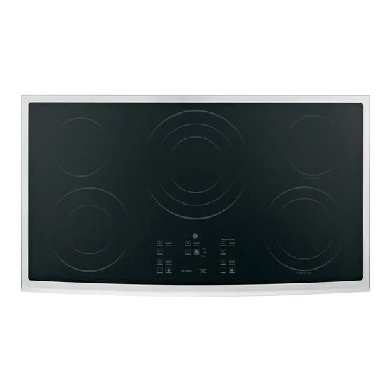
36" Electric Cooktop
JP655, PP962, PP972, PP975, PP980, ZEU36K
— Save these
— Observe all
— This appliance must
2 Hold Down
Brackets
MATERIALS YOU WILL NEED
Junction Box
TOOLS YOU WILL NEED
Pencil
Phillips Head
Screwdriver
—
Ruler or Straightedge
Safety Glasses
1
Wire Nuts
Saber Saw
1/8" Drill Bit & Electric
or Hand Drill
Advertisement
Table of Contents

Related Manuals for GE JP655SMSS


Summary of Contents for GE JP655SMSS
-
Page 1: Installation Instructions
Installation Instructions “If you have questions, call 800.GE.CARES or visit our website at: ge.com” BEFORE YOU BEGIN Read these instructions completely and carefully. IMPORTANT • — Save these instructions for local inspector’s use. IMPORTANT • — Observe all governing codes and ordinances. -
Page 2: Important Safety Instructions
If cabinet storage space is to be provided, the risk can be reduced by installing a range hood that projects horizontally a minimum of 5″ beyond the bottom of the cabinets. Cabinet installation above the cooktop may be no deeper than 13″. -
Page 3: Pre-Installation Checklist
PRE-INSTALLATION CHECKLIST WARNING – The electrical power to the cooktop supply line must be shut off while connections are being made. Failure to do so could result in serious injury or death. When preparing cooktop opening, make sure the inside of the cabinet and the cooktop do not interfere with each other. -
Page 4: Preparing The Opening
PREPARING THE OPENING The following MINIMUM clearance dimensions must be maintained. 13″ MAX. Depth of uprotected overhead cabinets 30″ MIN. Clearance from countertop to unprotected overhead surface 2″ MIN. Clearance from cutout to side wall on the left of the unit If a 30″... -
Page 5: Installing The Cooktop
INSTALLING THE COOKTOP INSTALLING THE JUNCTION BOX Install an approved junction box where it will be easily reached through the front of the cabinet where the cooktop will be located. The cooktop conduit is 4 feet long. Install junction box so that it can be reached through the front of the cabinet. -
Page 6: Insert Cooktop Into Cutout
INSTALLING THE COOKTOP INSERT COOKTOP INTO CUTOUT Insert the cooktop centered into the cutout opening. Make sure the front edge of the countertop is parallel to the cooktop. Make final check that all required clearances are met. Cooktop Hold Down Bracket Installation Instructions (CONT.) -
Page 7: Installation-Electrical Connections
INSTALLATION—ELECTRICAL CONNECTIONS When making the wire connections, use the entire length of conduit provided. The conduit must not be shortened. With the cooktop in place, open the front of the cabinet door. Insert the wires from the conduit through the opening of the junction box. Ground Black Connect the red and black leads from the... -
Page 8: Pre-Test Checklist
CHECKLISTS PRE-TEST CHECKLIST Remove all protective film, if present, and any stickers. Check to be sure that all wiring is secure and not pinched or in contact with moving parts. Check level of appliance. Check that the cooktop is properly grounded. - Page 9 Instrucciones de instalación “Si tiene alguna pregunta, llame al 800.GE.CARES o visite nuestro sitio Web en: ge.com” ANTES DE COMENZAR Lea estas instrucciones por completo y con cuidado. IMPORTANTE • — Conserve estas instrucciones para el uso del inspector local.
-
Page 10: Instrucciones De Seguridad Importantes
Instrucciones de instalación INSTRUCCIONES DE SEGURIDAD IMPORTANTES PARA SU SEGURIDAD • Para su seguridad personal, retire los fusibles de su hogar o bien abra el cortacircuitos antes de comenzar con la instalación. El no hacerlo puede resultar en lesiones serias o incluso la muerte. •... - Page 11 Instrucciones de instalación LISTA DE VERIFICACIÓN PREVIA A LA INSTALACIÓN ADVERTENCIA – eléctrica a la tubería de abastecimiento de la estufa debe cortarse durante la realización de conexiones. El no hacerlo puede resultar en una lesión seria o la muerte. Cuando se prepare para la abertura de la estufa, asegúrese que el interior del gabinete y la estufa no interfieran...
- Page 12 Instrucciones de instalación PREPARACIÓN DE LA ABERTURA Deben seguirse las siguientes dimensiones MÍNIMAS de espacio libre. 13″ MÁX. Profundidad de los gabinetes superiores sin protección 30″ MÍN. Espacio desde el mostrador hasta la superficie superior sin protección 2″ MÍN. Espacio desde el área cortada hasta la pared lateral a la izquierda de la unidad...
-
Page 13: Instalación De La Estufa
Instrucciones de instalación INSTALACIÓN DE LA ESTUFA INSTALACIÓN DE LA CAJA DE EMPALMES Instale una caja de empalmes aprobada en un lugar de fácil acceso a través del frente del gabinete en donde pueda colocarse la estufa. El conducto de la estufa tiene 4 pies de longitud. Instale la caja de empalmes de modo que pueda alcanzarse... - Page 14 Instrucciones de instalación INSTALACIÓN DE LA ESTUFA INSERTE LA ESTUFA EN EL ÁREA CORTADA Inserte la estufa centrada en el área cortada. Asegúrese de que el borde frontal del mostrador esté paralelo con respecto a la estufa. Asegúrese de verificar al final que todos los espacios especificados hayan sido respetados.
- Page 15 Instrucciones de instalación INSTALACIÓN—CONEXIONES ELÉCTRICAS Cuando realice las conexiones de cables, utilice toda la extensión del conducto incluido. El conducto no debe reducirse. Con la estufa colocada en su lugar, abra el frente de la puerta del gabinete. Inserte los cables del conducto a través de la abertura de la caja de empalmes.
- Page 16 Instrucciones de instalación LISTAS DE VERIFICACIÓN LISTA DE VERIFICACIÓN PREVIA Retire toda la película protectora, si la hay, y las calcomanías. Verifique que todos los cables estén fijos y que no estén torcidos o en contacto con partes móviles. Verifique el nivel del aparato. Verifique que la estufa esté...