Makita TW001G Instruction Manual
Hide thumbs
Also See for TW001G:
- Instruction manual (89 pages) ,
- Instruction manual (92 pages) ,
- Instruction manual (88 pages)
Table of Contents
Advertisement
Quick Links
Advertisement
Table of Contents

Related Manuals for Makita TW001G


Summary of Contents for Makita TW001G
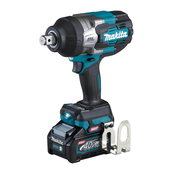
- Page 1 INSTRUCTION MANUAL Cordless Impact Wrench TW001G Read before use.
-
Page 2: Specifications
SPECIFICATIONS Model: TW001G Fastening capacities Standard bolt M12 - M36 High tensile bolt M10 - M27 Square drive 19.0 mm No load speed (RPM) Max impact mode (4) 0 - 1,800 min Hard impact mode (3) 0 - 1,400 min... -
Page 3: Ec Declaration Of Conformity
Work area safety WARNING: Wear ear protection. Keep work area clean and well lit. Cluttered or WARNING: dark areas invite accidents. The noise emission during actual use of the power tool can differ from the declared Do not operate power tools in explosive atmo- value(s) depending on the ways in which the tool is spheres, such as in the presence of flammable used especially what kind of workpiece is processed. - Page 4 Do not overreach. Keep proper footing and Keep cutting tools sharp and clean. Properly balance at all times. This enables better control maintained cutting tools with sharp cutting edges of the power tool in unexpected situations. are less likely to bind and are easier to control. Dress properly. Do not wear loose clothing or Use the power tool, accessories and tool bits jewellery.
- Page 5 CAUTION: Only use genuine Makita batteries. If electrolyte gets into your eyes, rinse them Use of non-genuine Makita batteries, or batteries that out with clear water and seek medical atten- have been altered, may result in the battery bursting tion right away. It may result in loss of your causing fires, personal injury and damage. It will also...
-
Page 6: Functional Description
Overload protection FUNCTIONAL This protection works when the tool is operated in a DESCRIPTION manner that causes it to draw an abnormally high cur- rent. In this situation, turn the tool off and stop the appli- cation that caused the tool to become overloaded. Then CAUTION: Always be sure that the tool is turn the tool on to restart. switched off and the battery cartridge is removed Overheat protection before adjusting or checking function on the tool. - Page 7 Switch action ► 1 . Button To turn on the lamp status, press the button for one second. To ► 1 . Switch trigger turn off the lamp status, press the button for one second again. With the lamp status ON, pull the switch trigger to turn on CAUTION: Before installing the battery car- the lamp. To turn off, release it. The lamp goes out approxi-...
-
Page 8: Changing The Application Mode
This tool has a reversing switch to change the direction of rota- tion. Depress the reversing switch lever from the A side for clock- wise rotation or from the B side for counterclockwise rotation. When the reversing switch lever is in the neutral posi- tion, the switch trigger cannot be pulled. - Page 9 NOTE: When none of the lamp on the panel is lit, pull the switch trigger once before pressing the button NOTE: All lamps on the switch panel go out when the tool is turned off to save the battery power. The impact force grade can be checked by pulling the switch trigger to the extent that the tool does not operate. Changing the application mode This tool employs several easy-to-use application modes for driving bolts with good control. The type of the application mode changes every time you press the button You can change the application mode within approximately one minute after releasing the switch trigger. NOTE: You can extend the time to change the application mode approximately one minute if you press the but- Application mode Feature Purpose (Assist type displayed on panel) Bolt mode Clockwise Clockwise This mode helps to repeat...
- Page 10 Application mode Feature Purpose (Assist type displayed on panel) Bolt mode (2) Clockwise – The tool stops automatically approximately 0.5 second later from the moment that the tool has started impact blows. Counterclockwise The impact force is 4. The tool stops automatically approximately 0.2 second later from the moment that the tool has stopped impact blows.
-
Page 11: Installing Hook
To remove the impact socket, follow the installation Proper fastening torque for high tensile bolt with procedures in reverse. max impact mode (4) Installing hook N•m (kgf•cm) CAUTION: When installing the hook, always 1600 (16315) secure it with the screw firmly. If not, the hook may come off from the tool and result in the personal 1400 (14276) -
Page 12: Maintenance
CAUTION: These accessories or attachments • Even though the diameters of bolts are the same, the are recommended for use with your Makita tool proper fastening torque will differ according to the specified in this manual. The use of any other torque coefficient, the class of bolt and the bolt length. accessories or attachments might present a risk of injury to persons. Only use accessory or attachment The use of the universal joint or the extension bar some- for its stated purpose.