Table of Contents
Advertisement
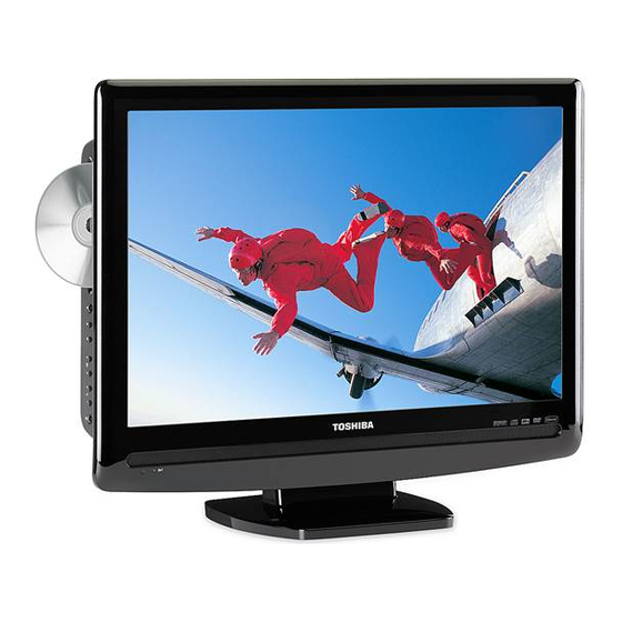
SERVICE MANUAL
19/22-inch Diagonal LCD
TV/DVD COMBINATION
The above models are classified as green products (*1), as indicated by the underlined serial numbers.
This Service Manual describes replacement parts for the green products. When repairing these green
product(s), use the part(s) described in this manual and lead-free solder (*2).
For (*1) and (*2), see the next page.
©2008 Toshiba Corporation
FILE NO. 810-200822GR
19LV505
19LV506
22LV505
DOCUMENT CREATED IN JAPAN, March, 2008 GREEN
Advertisement
Table of Contents
Troubleshooting

Related Manuals for Toshiba 19LV505


Summary of Contents for Toshiba 19LV505
- Page 1 This Service Manual describes replacement parts for the green products. When repairing these green product(s), use the part(s) described in this manual and lead-free solder (*2). For (*1) and (*2), see the next page. ©2008 Toshiba Corporation DOCUMENT CREATED IN JAPAN, March, 2008 GREEN...
- Page 2 Hazardous Substances. From July 1, 2006, the RoHS Directive will prohibit any marketing of new products containing the restricted substances. Increasing attention is given to issues related to the global environmental. Toshiba Corporation recognizes environmental protection as a key management tasks, and is doing its utmost to enhance and improve the quality and scope of its environmental activities.
- Page 3 SERVICING TO QUALIFIED SERVICE PERSONNEL. Sometimes TVs are improperly secured or inappropriately CAUTION: Changes or modifications to this equipment not expressly approved by Toshiba could void the user•• s authority to operate this situated on dressers, bookcases, shelves, desks, audio equipment.
- Page 4 TV: voltage surges and built-up static charges (see Follow all instructions. unplug the power cord and contact a Toshiba Section 810 of the National Electric Code.) 15) To avoid damage to this product, never place or Do not use this apparatus near water.
-
Page 5: Table Of Contents
DVD and CD Software and/or the manufacture of DVD and CD discs, Toshiba cannot assure that the DVD player contained in this TV will successfully play every disc bearing the DVD and CD logos. -
Page 6: Stop Button
• Always remove batteries from remote control if they are dead or if the remote control is not to be used for an extended instructions in “DVD menu ” Illustration of 19LV505 period of time This will prevent battery acid from leaking into the battery compartment... -
Page 7: Connecting To Optional Equipment
Your TV/DVD is capable of using ColorStream (component video). Connecting your TV/DVD to a component : Signal fl ow Back side (yellow) video compatible DVD player, such as a Toshiba DVD player with ColorStream ® can greatly enhance picture Camcorder (white) quality and performance. -
Page 8: Power Source
Connect the AC cord plug into this TV/DVD’s AC INPUT jack. press • • or • • to select “Air” or “Cable”. Connect the AC cord into an AC outlet. Auto Setup Illustration of Language English 19LV505 Signal Type Cable AC Outlet Automatic Search Start Wider Hole... -
Page 9: Tv Operation
Basic setup To memorize channels (Continued) ENTER ENTER / / / EXIT/CANCEL EXIT/CANCEL MENU MENU Add/Delete channel Adding Channel Clear All If you find a new channel unregistered, you can add the All channels are deleted from the channel memory. You can select the channel that you want to skip. -
Page 10: Labeling Channels
TV operation Labeling channels Labeling video inputs Channel label appear with the channel number display each time you turn on the The Video Label feature allows you to label each input source for your TV/DVD. TV/DVD, select a channel, or press DISPLAY. You can choose any four characters to identify a channel. -
Page 11: Setting The Closed Captions
TV operation Setting the V-Chip (continued) As a supplement to the standard V-Chip rating system, your television will 0–9 be able to download an additional rating system, if such a system becomes available in the future. MUTE ENTER ENTER / / / EXIT/CANCEL MENU To set the V-Chip (Continued) -
Page 12: Adjusting The Picture Preference
Standard Standard picture quality (factory-set) former ratio. Warm Reddish • 19LV505/19LV506: In ColorStream HD/HDMI mode The top and bottom edges of the picture may be hidden. Movie Movie-like picture setting (factory-set) with a scanning rate of 720p or 1080i, only the... -
Page 13: Sound Control Adjustment
TV operation Sound control adjustment/ Selecting the audio language/ Selecting Stereo/Second Audio Program (SAP) Selecting the HDMI audio input source The multi-channel TV sound (MTS) feature provides high-fidelity stereo sound. When two or more audio languages are included in a digital signal, you can MTS also can transmit a second audio program (SAP) containing a second select one of the audio language. -
Page 14: Basic Playback
Basic playback TV/DVD Playing a disc POWER EJECT EJECT This section shows you the basics on how to play a disc. To obtain a higher quality picture VOLUME + /– Occasionally, some picture noise may appear on the TV screen while playing a DVD video disc because the high resolution pictures on these discs include a + /–... -
Page 15: Marking Desired Scenes
Advanced playback Repeat playback/A-B Repeat playback Marking desired scenes PLAY MODE The unit stores the points that you want to watch again up to 3 points. ENTER You can resume playback from each scene. ENTER PLAY SKIP EXIT/CANCEL REPEAT A-B MARKER Marking the scenes Returning to the scenes... -
Page 16: Changing Soundtrack Language
MP3/WMA and Audio CD playback You must obtain any required permission from copyright owners to download or use copyrighted content. Toshiba cannot and does not grant such permission. Load an Audio CD or a disc on which MP3 About fi le menu Audio CD/MP3/WMA/JPEG/DivX ®... -
Page 17: Repeat, Random And Program Playback Using File Browser
Advanced playback Advanced playback ZOOM ® MP3/WMA/JPEG/DivX and Audio CD DVD MENU ENTER operation (Continued) / / / PAUSE STOP ENTER PLAY SKIP STOP ANGLE PLAY TOP MENU ® ® JPEG playback Slide show playback DivX playback Playing DivX VOD content The slide show enables you to view pictures (fi... -
Page 18: Function Setup
Function setup TV/DVD Customizing the function settings You can change the default settings of the DVD mode to customize performance to your preference. Press TV/DVD on the remote control to select DVD mode. / / / ENTER SETUP RETURN Setting details Setting procedure Press SETUP during stop mode. -
Page 19: Temporary Cancel The Rating Level By Dvd Disc
Function setup EJECT Customizing the function settings (Continued) Temporary cancel the rating level by DVD disc 0–9 Depending on the DVD disc, the disc may try to temporarily cancel the rating level that you have set. It is up to you to decide whether to cancel the rating level or not. ENTER RETURN Setting details (continued) -
Page 20: Reception Disturbances
Model 19LV505 / 19LV506 22LV505 Toshiba America Consumer Products, L.L.C. (“TACP”) makes the following limited warranties to original General consumers in the United States. THESE LIMITED WARRANTIES EXTEND TO THE ORIGINAL CONSUMER PURCHASER OR ANY PERSON RECEIVING THIS LCD TV/DVD COMBINATION AS A GIFT FROM THE... - Page 21 • Place the unit on a workstation equipped to protect against static electricity, such as conductive mat. • Soldering iron with ground wire or ceramic type is used. • A worker needs to use a ground conductive wrist strap for body. A1-1 19LV505/19LV506/22LV505...
- Page 22 The MODEL NUMBER can be found on the back of each product and the VERSION LETTER can be found at the end of the SERIAL NUMBER. 2. PART NO. and DESCRIPTION You can find it in your SERVICE MANUAL. A1-2 19LV505/19LV506/22LV505...
- Page 23 18) Do not push objects through any openings in this unit, as they may touch dangerous voltage points or short out parts that could result in fire or electric shock. Never spill or spray any type of liquid into the unit. A1-3 19LV505/19LV506/22LV505...
- Page 24 24) Reduce the volume to the minimum level before you turn on the product. Otherwise, sudden high volume sound may cause hearing or speaker damage. A1-4 19LV505/19LV506/22LV505...
- Page 25 If the liquid gets in your mouth, immediately gargle and consult with your doctor. Also, if the liquid gets in your eyes or touches your skin, consult with your doctor after rinsing for at least 15 minutes or longer in clean water. A1-5 19LV505/19LV506/22LV505...
- Page 26 • Soldering combination: Sn-3.0Ag-0.5Cu • When Soldering/Removing of solder, use the draw in equipment over the Pick Up Unit to keep the Flux smoke away from it. Pick Up PCB Short circuit using a soldering iron. Fig. 1 A1-6 19LV505/19LV506/22LV505...
- Page 27 Press and hold the “STOP” button on the side panel. Simultaneously press and hold the “7” key on the remote control unit. Hold both keys for more than 2 seconds. The On Screen Display message “PASSWORD CLEAR” will appear. The 4 digit password has now been cleared. A1-7 19LV505/19LV506/22LV505...
- Page 28 45 BA 42 ANGLE 44 BB 43 MARKER 45 BA 44 SLOW |> 44 BB 45 TOP MENU 44 BB 46 RETURN 44 BB 47 REPEAT A-B 44 BB 48 GAME 40 BF 49 PICTURE SIZE 40 BF A1-8 19LV505/19LV506/22LV505...
- Page 29 INTERCONNECTION DIAGRAM ....................H-65~H-70 WAVEFORMS ..........................I-1, I-2 MECHANICAL EXPLODED VIEW ....................J1-1~J1-9 DVD DECK EXPLODED VIEW ....................J2-1 MECHANICAL REPLACEMENT PARTS LIST ................K1-1~K1-3 DVD DECK REPLACEMENT PARTS LIST ................K2-1~K2-3 ELECTRICAL REPLACEMENT PARTS LIST ................K3-1~K3-15 19LV505/19LV506/22LV505 A2-1...
-
Page 30: General Specifications
Audio Signal Input Level -8.0dBm/50k ohm Output Level at DVD at TV Digital Output Level 0.5 V p-p/75 ohm S/N Ratio at DVD (Weighted) Harmonic Distortion Frequency Response : at DVD at Video CD at SVCD at CD A3-1 19LV505... - Page 31 G-10 Remote Unit RC-LT Glow in Dark Remocon Control Remocon Format TOSHIBA Format TOSHIBA Custom Code 40-BF h ,44-BB h ,45-BA h ,45-BC h Power Source Voltage(D.C) UM size x pcs UM-4 x 2 pcs Total Keys 49 Keys A3-2 19LV505...
- Page 32 Menu / Setup Exit / Cancel Game Picture Size Pause Play Stop Skip+ / Closed Caption Skip- / CH Return Search+ Search- Slow+ Slow- Angle Maker Top Menu Return Closed Caption Repeat A-B Zoom/ Quick View Freeze frame A3-3 19LV505...
- Page 33 RRT Setup Lock Hotel Lock Channel Lock Video Lock Panel Lock English Menu Language French Spanish Closed Caption CC Advanced Picture Size HD Zoom Picture Scroll Film Mode Aspect Backlight PFC(Power Factor circuit) Freeze frame PIP/POP Direct Input Selection A3-4 19LV505...
- Page 34 MP3 Playback JPEG Divx Playback DMF Support Digital Out (Dolby Digital) (MPEG) (PCM) (DTS) Down Mix Out (Dolby Digital) (DTS) Closed Caption Screen Saver TV Screen 4:3 (Letter Box, Pan Scan) 16:9 (Wide) Audio DAC 192kHz / 24bit A3-5 19LV505...
- Page 35 Volume Down/Menu < Menu Play No (CH+ Alternative) Eject Skip+, Search+ Skip-, Search- Still/Pause Stop No (CH- Alternative) Main Power SW Input Select/Enter Rear Main Power SW Indicator Power/Stand-By Yes (Green / Red) Power Wake Up On Timer A3-6 19LV505...
- Page 36 Container Stuffing (40' container) 1088 Sets/40' container w/Pallet w/Wrapping Cabinet Front PC+ABS 94V0 NON-HALOGEN G-17 Material Rear PS 94V0 NON-DECABROM Jack Panel Non-Halogen Demand Eyelet Demand G-18 Environment Environmental standard requirement Green procurement of ORION Pb-free Phase3(Phase3A) Measures for Whisker A3-7 19LV505...
- Page 37 GENERAL SPECIFICATIONS LCD Size / Visual Size 18.95 inch / 481.41mmV LCD Type Color TFT LCD System Number of Pixels 1440(H) x 900(V) View Range Left/Right 80/80 degree Up/Down 80/80 degree < Bright Dot n = 0 Zero Bright Dot Ratio Color System NTSC Speaker...
- Page 38 Timer Back-up (at Power Off Mode) more than G-10 Remote Unit RC-LT Glow in Dark Remocon Control Remocon Format TOSHIBA Format TOSHIBA Custom Code 40-BF h ,44-BB h ,45-BA h ,45-BC h Power Source Voltage(D.C) UM size x pcs UM-4 x 2 pcs...
- Page 39 GENERAL SPECIFICATIONS Keys Power Eject Sleep TV/DVD Jump / - Display Subtitle Audio Select Input Select / Zoom Mute CH Up CH Down Vol Up Vol Down Play Mode DVD Menu Down Left Right Enter Menu / Setup Exit / Cancel Game Picture Size Pause...
- Page 40 GENERAL SPECIFICATIONS G-11 Features Auto Shut Off Auto Search Power On Memory Comb Filter Game Position Auto Setup(Language/CH Program) Picture Setting(TV) Picture Preference Brightness , Contrast , Color Tint Sharpness Color Temperature Cable Clear Picture Setting(PC) HOR Position , VER Position Phase, Clock Red, Green, Blue Auto Adjust...
- Page 41 GENERAL SPECIFICATIONS Digital Out Dolby Digital MPEG PC Monitor Input VGA (640x480) Yes (60Hz) VGA (720x400) Yes (70Hz) WVGA (848x480) SVGA (800x600) Yes (60Hz) XGA (1024x768) Yes (60Hz) WXGA (1280x768) Yes (60Hz) WXGA (1280x720) Yes (60Hz) WXGA (1360x768) Yes (60Hz) SXGA (1280x1024) HDMI Input VGA (640×480)
- Page 42 GENERAL SPECIFICATIONS G-12 Accessories Owner's Manual Language English w/Guarantee Card Remote Control Unit Rod Antenna Poles Terminal Loop Antenna Terminal U/V Mixer DC Car Cord (Center+) Guarantee Card Warning Sheet Circuit Diagram Antenna Change Plug Service Facility List Important Safeguard Dew/AHC Caution Sheet Quick Set-up Sheet (Spanish) Battery...
- Page 43 GENERAL SPECIFICATIONS Terminals Rear Video Input 1 RCA x 1 Audio Input 1 RCA x 2(L/MONO, R) S - Input 1 Video Input 2 Audio Input 2 S - Input 2 Video Output Audio Output Component Input 1 RCA x 3 Analog Audio RCA x 2(L/MONO, R) Component Input 2...
- Page 44 GENERAL SPECIFICATIONS LCD Size / Visual Size 22.0 inch / 558.00mmV System LCD Type Color TFT LCD Number of Pixels 1680(H) x 1050(V) View Range Left/Right 85/85 degree Up/Down 80/80 degree < Bright Dot n = 0 Zero Bright Dot Ratio Color System NTSC Speaker...
- Page 45 Timer Back-up (at Power Off Mode) more than G-10 Remote Unit RC-LT Control Glow in Dark Remocon Remocon Format TOSHIBA Format TOSHIBA Custom Code 40-BF h ,44-BB h ,45-BA h ,45-BC h Power Source Voltage(D.C) UM size x pcs UM-4 x 2 pcs...
- Page 46 GENERAL SPECIFICATIONS Keys Power Eject Sleep TV/DVD Jump / - Display Subtitle Audio Select Input Select / Zoom Mute CH Up CH Down Vol Up Vol Down Play Mode DVD Menu Down Left Right Enter Menu / Setup Exit / Cancel Game Picture Size Pause...
- Page 47 GENERAL SPECIFICATIONS G-11 Features Auto Shut Off Auto Search Power On Memory Comb Filter Game Position Auto Setup(Language/CH Program) Picture Setting(TV) Picture Preference Brightness , Contrast , Color Tint Sharpness Color Temperature Cable Clear Picture Setting(PC) HOR Position , VER Position Phase, Clock Red, Green, Blue Auto Adjust...
- Page 48 GENERAL SPECIFICATIONS Digital Out Dolby Digital MPEG PC Monitor Input VGA (640x480) Yes (60Hz) VGA (720x400) Yes (70Hz) WVGA (848x480) SVGA (800x600) Yes (60Hz) XGA (1024x768) Yes (60Hz) WXGA (1280x768) Yes (60Hz) WXGA (1280x720) Yes (60Hz) WXGA (1360x768) Yes (60Hz) SXGA (1280x1024) HDMI Input VGA (640×480)
- Page 49 GENERAL SPECIFICATIONS G-12 Accessories Owner's Manual Language English w/Guarantee Card Remote Control Unit Rod Antenna Poles Terminal Loop Antenna Terminal U/V Mixer DC Car Cord (Center+) Guarantee Card Warning Sheet Circuit Diagram Antenna Change Plug Service Facility List Important Safeguard Dew/AHC Caution Sheet Quick Set-up Sheet(Spanish) Battery...
- Page 50 GENERAL SPECIFICATIONS Terminals Rear Video Input 1 RCA x 1 Audio Input 1 RCA x 2(L/MONO, R) S - Input 1 Video Input 2 Audio Input 2 S - Input 2 Video Output Audio Output Component Input 1 RCA x 3 Analog Audio RCA x 2(L/MONO, R) Component Input 2...
-
Page 51: Disassembly Instructions
Remove the 3 screws (2). Remove the Operation PCB in the direction of arrow (B). CP2804 CD7006 CP7601 CD7005 Remocon PCB CP2201 (2) (2) Operation PCB Digital PCB LCD Panel Fig. 1-2 CP3002 Spring Earth 1 (1) (1) Fig. 1-4 B1-1 19LV505/19LV506/22LV505... - Page 52 Pick Up Unit to keep the Flux smoke away from it. When installing the DVD Deck, remove all the soldering on the short circuit position after the connection of Pick Up PCB and DVD MT PCB connector. B1-2 19LV505/19LV506/22LV505...
-
Page 53: Removal Of Dvd Deck Parts
Switch PCB Ass'y 80 ± 5mm • Screw Torque: 1.3 ± 0.3kgf•cm (Screw 2) • Screw Torque: 3.0 ± 0.3kgf•cm (Screw 3) • Screw Torque: 1.0 ± 0.3kgf•cm (Screw 4, 5) Fig. 2-2-A Loader Ass'y Check Hook Fig. 2-1-C B2-1 19LV505/19LV506/22LV505... - Page 54 Fold of the insert. Fig. 2-2-C Switch PCB Ass'y ~ FEED MOTOR ~ WHITE (4) BROWN (3) • Install wire from (1) to (4) in order. Fig. 2-3-B ~ SPINDLE MOTOR ~ YELLOW (2) GREEN (1) Fig. 2-2-D B2-2 19LV505/19LV506/22LV505...
-
Page 55: Removal And Installation Of Flat Package Ic
NOTE Do not move the Braided Shield Wire in the vertical direction towards the IC pattern. Blower type IC desoldering machine Braided Shield Wire Soldering Iron IC pattern Fig. 3-4 Fig. 3-2 B3-1 19LV505/19LV506/22LV505... - Page 56 Fig. 3-6 Absorb the solder left on the lead using the Braided Shield Wire. (Refer to Fig. 3-7.) NOTE Do not absorb the solder to excess. Soldering Iron Braided Shield Wire Fig. 3-7 B3-2 19LV505/19LV506/22LV505...
-
Page 57: Service Mode List
Adjustment). Check of the firmware version. DVD mode STOP 2 sec. Refer to the "RE-WRITE FOR DVD FIRMWARE". (No disc) DVD mode Releasing of PARENTAL LOCK. STOP 2 sec. (No disc) Refer to the "PARENTAL CONTROL - RATING LEVEL". 19LV505/19LV506/22LV505... -
Page 58: Servicing Fixtures And Tools
A D L J B 8 1 1 1 A ADLJB8111A Fixed Released times on the same date Release date (Example: 2008.01.11) When the changed version displays, the Re-write will be completed. A = October B = November C = December Turn off the power 19LV505/19LV506/22LV505... -
Page 59: When Replacing Eeprom (Memory) Ic
Press both VOL. DOWN button on the set and Channel button (1) on the remote control for more than 2 seconds. After the finishing of the initializing of shipping, the unit will turn off automatically. The unit will now have the correct DATA for the new MEMORY IC. 19LV505/19LV506... - Page 60 WHEN REPLACING EEPROM (MEMORY) IC CONFIRMATION OF CHECK SUM, POWER ON TOTAL HOURS AND MICON VERSION Initial total of MEMORY IC, POWER ON total hours and MICON VERSIONcan be checked on the screen. Total hours are displayed in 16 system of notation. NOTE: If you set a factory initialization, the total hours is reset to "0".
-
Page 61: Electrical Adjustments
INPUT ZOOM button on the remote control. Receive the DIGITAL broadcasting. To display the adjustment screen for DTV mode, select the digital channel. Press the VOL.DOWN button on the set and the channel (9) on the remote control for more than 2 seconds. 19LV505/19LV506/22LV505... - Page 62 SHARP H2 MIN SHARP V1 MAX SHARP V1 MIN CONTRAST CENTER CONTRAST MAX CONTRAST MIN COLOR CENT COLOR MAX COLOR MIN CONTRAST 40 For the step no. with * mark, please adjust it according to the situation of the set. NOTE: 19LV505/19LV506...
- Page 63 ELECTRICAL ADJUSTMENTS 2-3: Confirmation of Fixed Value (Step No.) Please check if the fixed values of each of the adjustment item is set correctly referring below. (TV/AV/GAME/COMPONENT/HDMI/DVD/PC/DTV) GAME COMPONENT HDMI FUNCTION CVBS 480i 480p 720p 1080i 480i 480p 720p 1080i 640*480 720*400 800*600 1024*768 1280*768...
- Page 64 DVD MT PCB DVD DECK CP2301 CD2001 CP2302 CP8502 CP2303 CD2301 OPERATION PCB CP2201 CD7005 CP7601 OS7601 REMOCON PCB CD7006 CD3002 CD2804 CP3002 CP2804 J8101 J8104 J501 J301 TU5801 J4302 CP3602 J4301 CD301 J8103 POWER PCB CP4303 DIGITAL PCB SPEAKER 19LV505/19LV506/22LV505...
-
Page 65: Troubleshooting Guide
TROUBLESHOOTING GUIDE (LCD SECTION) POWER DOES NOT TURN ON Change F501. Is F501 broken? Check IC501 and peripheral Is there voltage at pin circuit. 6 of IC501 21V? Is R510 broken? Change R510. Change Digital PCB. 19LV505/19LV506/22LV505... - Page 66 Is there signal at pins 1 peripheral circuit. and 2 of IC6551? Is there signal at pin Check IC6552,IC6553 and 3 of IC6552,IC6553? peripheral circuit. Is there signal at pin Check IC5801 and peripheral 5 of TU5801? circuit. Change TU5801. 19LV505/19LV506/22LV505...
- Page 67 20 of IC7001 12V ? Is CD2804 connected? Connected CD2804. Is there voltage at pins 1,2 Check Q3009 and peripheral and 16 of CP2804 5V? circuit. Is there signal at pins 5,6,7, 8,9,11,12,13,14,15,20,21, Change V2801(PANEL). 22,23,24,26,27,28,29 and 30 of CP2804? Change DIGITAL PCB. 19LV505/19LV506/22LV505...
- Page 68 TROUBLESHOOTING GUIDE THE COLOR DOES NOT APPEAR Is setting of color Adjust the color. normal? Is the color signal Receive the color signal. received? Is there color signal Check IC2801 and at IC2801? peripheral circuit. Change DIGITAL PCB. 19LV505/19LV506/22LV505...
- Page 69 Does this display Check the disc. logo picture? Check pins 8 and 10 of Is there signal at pins 149 CP8501 and peripheral circuit. and 151 of IC4001? Does IC4001 gets P.CON+3.3V and Change IC4001. P.CON+1.8V? Check P.CON+3.3V and P.CON+1.8V line. 19LV505/19LV506/22LV505...
- Page 70 Check IC4001 and Does this eject disc at Is there signal at pins 4 peripheral circuit. change DVD DECK? and 5 of CP2302? Change DVD DECK. Is there signal at pins 1 Change IC2301. and 2 of CP2302? Change IC4001. 19LV505/19LV506/22LV505...
- Page 71 Change DVD DECK. Is the voltage between Does CD2001 connect Does this display JG017 and JG018 less with CP2301 correctly? "INCORRECT DISC"? than 0.6V? Connect CD2301. Does this display Change IC4001. reading mark? Change DVD DECK. Does disc rotate? Change IC4001. 19LV505/19LV506/22LV505...
- Page 72 Change DVD DECK. Is the voltage between Does CD2001 connect Does this display JG019 and JG018 less with CP2301 correctly? "INCORRECT DISC"? than 0.6V? Connect CD2301. Does this display Change IC4001. reading mark? Change DVD DECK. Does disc rotate? Change IC4001. 19LV505/19LV506/22LV505...
- Page 73 7 of IC8501? Connected CD8501. Does CD8501 connected? Change DIGITAL PCB. NO SOUND DVD/CD DIGITAL AUDIO Is there signal at pin1 Change DIGITAL PCB. of CP8501? Is there signal at pin122 Check line circuit IC4001 of IC4001? to CP8501. Change IC4001. 19LV505/19LV506/22LV505...
- Page 74 MOTOR AUDIO AMP DVD_AUDIO_L HOME, TIN_SW, TOUT_SW DVD_A_OUT_L IC8501 APWM_L+/-, DVD_AUDIO_R NJM4565M(TE1) DVD_A_OUT_R APWM_R+/- HA0~A19, HD0~D15, MEMCS0, RD, WR SD_A0~A11 64M SDRAM SD_D0~D15 FLASH 16M IC4005 IC4007 M12L64164A-7TG SST39VF1601-70-4C-EKE RAMDQM, CLK, CKE, WE#, CAS#, CS0#, CS1#, RAS# SD_BA0, DQM 19LV505/19LV506/22LV505...
- Page 75 PS2561AL1-1-V(W) IC502 KIA431A-AT CP501__2.FILTER_MUTE CP501__20.INVERTER_H CP501 19.LIGHT CTL T7001 CD7005 14.HV DRIVE CD7005 7.LV Q7005 CD7005 8.LV CD7005 1.HV CD7005 14.HV CD7005 7.LV DRIVE CD7005 8.LV Q7004 T7002 CD7005 1.HV INVERTER CONTROLLER IC7001 DRIVE Q7003 BD988SFV-E2 FEED_BACK IC7002 LM2902DR 19LV505/19LV506/22LV505...
-
Page 76: Power
DDR SDRAM FLASH IC IC2804 IC3003 1.8V IC2802 EN29LV320AB-70TCP PQ035ZN1HZPH HYB18TC256160BF-3S LCD+B SW LCD PANEL Q3009 V2801 RTQ035P02-TR T190PW01_V0 AUDIO Lch SW AUDIO Rch SW AUDIO Lch SW AUDIO Lch SW IC6552 IC6553 IC6557 IC6558 NJM2534V(TE2) NJM2534V(TE2) NJM2534V(TE2) NJM2534V(TE2) 19LV505/19LV506... - Page 77 POWER(DIGITAL PCB) BLOCK DIAGRAM 5.0V 5.0V REGULATOR IC3007 BD7820FP-E2 3.3V REGULATOR IC3009 CP3001 S-1170B33UC-OTSTFG FILTER MUTE AT3.3V DIGITAL TUNER TUNER+30V TU5801 ENG36E18KRF AT+12V SUB MICON EEPROM IC6202 IC2805 AT+5.8V R5F21124FP M24256-BWMN6TP BTSC DEMODULATOR AUDIO ADC IC5801 IC6551 AN5832SA-E1V AK5358A VDD CORE 1V IC3001 BD9130NV SCALER IC...
-
Page 78: Signal
PC G TUNER DIGITAL RF (IF) WD-00021-R TU5801 PC B ENG36E18KRF ANALOG RF(CVBS) S VIDEO IN AV1_Y SW_Y_IN J8101 AV1_C DIN-417HA-01 DVD CP3002 DVD_A_OUT_R DIGITAL_A_SW DVD_A_OUT_L IC6556 SPDIF-134 SN74LVC1G3157DCKR [Y]VIDEO [U]C_VIDEO START_SW SUB MICON DVD_RESET IC6202 ZERO R5F21124FP 19LV505/19LV506 F-10... - Page 79 SIGNAL BLOCK DIAGRAM HEADPHONE JACK J301 PJ-364H COAXIAL J4301 SPEAKER L/R RCH-101HT(OR) SP301, SP302 NB073N1-B1 COMPONENT Y SPDIF AMP L/R COMPONENT IN COMPONENT U J8102 AUDIO L/R SOUND AMP IC RCA-341H(NI)-09 COMPONENT V IC301 LA42052-E AV 1 CVBS CVBS _AV_IN AV1_A_IN_L J8104 RCA-341H(2)NI-06...
-
Page 80: Printed Circuit Boards
R8533 R4009 C8516 B8503 C4077 C8531 C4024 R8535 R8529 W824 IC4005 C4018 C4023 C4025 C4030 R8536 R8531 C8543 C4038 C8525 C4026 DMG097A C8537 C8536 D8510 C4009 C4083 B4006 C8542 C4067 C4050 B4008 C4036 C4045 C4046 C4047 DMG097A CP8501 NTSC 19LV505/19LV506... - Page 81 PRINTED CIRCUIT BOARDS DVD MT (TOP SIDE) DVD MT (BOTTOM SIDE) MOTOR C2332 R2355 C2323 C2326 R2341 R2309 W813 R2340 C2331 C2339 C2309 C2317 C2327 CP2301_1 C2329 C2338 B2304 CP2302 R2350 C2321 W812 C4059 C2336 C2350 C2340 R2353 C2316 R4019 R4043 B4002 R4018...
-
Page 82: Digital
R2840 R6231 C2935 R6233 B2811 B2821 C4317 C4313 B2815 D6212 B6552 C4318 B2814 B2816 D6209 R4304 R4303 B2817 Q3603 L6561 R4305 R3643 R3631 R3630 R6558 R6559 Q3608 Q3607 Q3610 J4302 L3603 C2939 L3604 R3602 W878 C5814 CP3602 B4301 CP4303 19LV505/19LV506... - Page 83 C2917 C2909 C2913 C2941 C2949 NR6551 R2808 C5852 C5853 C2912 C2803 R3633 C3616 C3613 IC6551 Q6204 C5805 C2927 R6560 Q6203 C2950 C5804 IC5801 R4343 R4346 R4347 B3601 R3614 D3607 R3616 D3611 IC3602 R5811 B6551 C6554 Q5802 Q5801 B4302 Q4301 19LV505/19LV506...
- Page 84 PRINTED CIRCUIT BOARDS DIGITAL (TOP SIDE) W851 W849 CP2803 CP3002 CP2804 C2807 R3004 R3003 B3022 B3023 CP6201 B2800 C3065 C3066 CEG360A Q3002 Q3001 B3012 SCALER CP2801 NTSC B3011 C3023 B3010 R2817 D3007 B3009 C3024 W861 IC3007 IC2802 MICON C3026 Q3411 C3027 Q3410 R3032...
- Page 85 PRINTED CIRCUIT BOARDS DIGITAL (BOTTOM SIDE) W852W853 Q3008 R3041 Q3007 Q3004 Q3003 R3014 R3015 R3017 R3013 C2816 IC3002 C3018 R3022 C2814 R3020 R3007 C2819 C3031 C2817 C3029 C3056 IC3001 B3004 B3017 B3005 C2823 C3021 C2824 C2825 C6210 C2821 C2826 R3431 R2818 R2819 Q3006...
-
Page 86: Power/Operation/Remocon
J301 J8102 R7056 R507 W011 W836 D506 J8103 W004 IC505 C523_1 D516 C307 W018 W017 C516 W014 R7004 IC501 IC502 J8104 W025 Q504 W835 W016 HS301 Q503 C512 IC301 L504 S803X W806 C304 CEG362A CP501 CP8101 S803Y 19LV505/19LV506 G-14 G-13... - Page 87 CEG362A IC503 Q505 Q301 R531 Q302 D521 R7003 R523 R515 R7002 R7006 R525 R7005 R7008 R7019 R8104 R519 IC7001 R513 R502 Q7003 R544 CEG364A R7037 R7603 IC7002 R7602 D7016 D7025 D7021 R2204 R2205 R2206 CEG363A R2201 R2202 19LV505/19LV506 G-16 G-15...
- Page 88 PRINTED CIRCUIT BOARDS POWER/OPERATION/REMOCON (INSERTED PARTS) SOLDER SIDE CP2201 CEG363A CD7005 FH502 W031 CD7006 SW2203 W013 T7001 R7049 AS MARKED. R7050 - REPLACE W810 C7026 RISK OF FIRE W023 FH501 R7051 W808 C7020 OS7601 R7052 R7039 C510 T7002 D7006 C508 D7008 L501 R7036_1...
- Page 89 PRINTED CIRCUIT BOARDS POWER/OPERATION/REMOCON (CHIP MOUNTED PARTS) SOLDER SIDE CEG362A IC503 Q505 Q301 R531 Q302 D521 R7003 R523 R515 R7002 R7006 R7005 R525 R7008 R7019 R8104 R519 IC7001 R513 R502 Q7003 R544 R7037 R7603 IC7002 R7602 D7016 D7025 D7021 CEG363A R2204 R2205 R2206...
- Page 90 PRINTED CIRCUIT BOARDS SOLDER SIDE DED020A M2602 M2601 G-21 19LV505/19LV506/22LV505...
-
Page 91: Mpeg/Micon/Dsp/Rf_Amp
RAMCKE PCB130 DMG097 NOTE:THE DC VOLTAGE EACH PART WAS NOTE:THIS SCHEMATIC DIAGRAM IS THE LATEST AT THE TIME DEBUG MODE DEL OF PRINTING AND SUBJECT TO CHANGE WITHOUT NOTICE MEASURED WITH THE DIGITAL TESTER RELEASE MODE ADD DURING PLAYBACK. 19LV505/19LV506/22LV505... -
Page 92: Memory
EBMS160808A102_RDC45 FROM AUDIO/VIDEO MEMCS0 P.CON+3.3V_D D_GND RESET PCB130 DMG097 NOTE:THIS SCHEMATIC DIAGRAM IS THE LATEST AT THE TIME NOTE:THE DC VOLTAGE EACH PART WAS OF PRINTING AND SUBJECT TO CHANGE WITHOUT NOTICE MEASURED WITH THE DIGITAL TESTER DURING PLAYBACK. 19LV505/19LV506/22LV505... - Page 93 DANGEREUSES AN POINT DE VUE SECURITE CRITICAL FOR SAFETY,USE ONES OF PRINTING AND SUBJECT TO CHANGE WITHOUT NOTICE MEASURED WITH THE DIGITAL TESTER N’UTILISER QUE CELLS DECRITES DESCRIBED IN PARTS LIST ONLY DURING PLAYBACK. DANS LA NOMENCLATURE DES PIECES 19LV505/19LV506/22LV505...
-
Page 94: Audio/Video
DANGEREUSES AN POINT DE VUE SECURITE NOTE:THE DC VOLTAGE EACH PART WAS DESCRIBED IN PARTS LIST ONLY OF PRINTING AND SUBJECT TO CHANGE WITHOUT NOTICE N’UTILISER QUE CELLS DECRITES MEASURED WITH THE DIGITAL TESTER DANS LA NOMENCLATURE DES PIECES DURING PLAYBACK. 19LV505/19LV506... - Page 95 AUDIO/VIDEO SCHEMATIC DIAGRAM (DVD MT PCB) FROM/TO REGULATOR CP8502 (CP3002) A2001WV2-8P GND(M) B8501 P.CON+6V_D P.CON+6V BLM18PG121SN1D P.CON+A5V B8504 P.CON+12V FROM/TO MPEG/MICON/DSP/RF_AMP EBMS160808A102_RDC45 M_GND P.CON+3.3V P.CON+5V_D C8505 DAC_VIDEO_C/D DAC_C[U]C_VIDEO P.CON+3.3V L8501 DAC_VIDEO_C/D B8502 P.CON+A5V_D 12P CH EBMS160808A102_RDC45 2.2uHNLV25 L8502 DAC_VIDEO_A RESET 1uHNLV25 SYS_MUTE DUPRD1...
-
Page 96: Micon
NOTE:THE DC VOLTAGE AT EACH PART WAS MEASURED NOTE:THIS SCHEMATIC DIAGRAM IS THE LATEST AT THE TIME WITH THE DIGITAL TESTER WHEN THE COLOR BROADCAST OF PRINTING AND SUBJECT TO CHANGE WITHOUT NOTICE WAS RECEIVED IN GOOD CONDITION AND PICTURE IS NORMAL. 19LV505/22LV505 H-12 H-11... - Page 97 MICON SCHEMATIC DIAGRAM (DIGITAL PCB) FROM OPERATION CD6202 (CP2201) CH231204 W914 B6201 FCM1608KF-102T02 KEY_B1 KEY B B6202 FCM1608KF-102T02 KEY_A1 TO AV SWICTH KEY A RESET_N FROM/TO SCALER VIDEO/AUDIO Q6201 2SK3019_TL Q6202 MCU_SCITXD 2SK3019_TL MCU_SCIRXD I2C_DATA FROM WRITER I2C_CLK SUB MICON CP6201 A2001WV-11A TO JACK FLASH_WRITE_TXD...
- Page 98 NOTE:THIS SCHEMATIC DIAGRAM IS THE LATEST AT THE TIME NOTE:THE DC VOLTAGE AT EACH PART WAS MEASURED OF PRINTING AND SUBJECT TO CHANGE WITHOUT NOTICE WITH THE DIGITAL TESTER WHEN THE COLOR BROADCAST WAS RECEIVED IN GOOD CONDITION AND PICTURE IS NORMAL. H-15 19LV505/19LV506/22LV505 H-16...
- Page 99 :LES PIECES REPAREES PAR UN ETANT TU_AUDIO_L DANGEREUSES AN POINT DE VUE SECURITE WITH THE DIGITAL TESTER WHEN THE COLOR BROADCAST WAS RECEIVED IN GOOD CONDITION AND PICTURE IS NORMAL. N’UTILISER QUE CELLS DECRITES DANS LA NOMENCLATURE DES PIECES H-17 19LV505/19LV506/22LV505 H-18...
- Page 100 NOTE:THE DC VOLTAGE AT EACH PART WAS MEASURED NOTE:THIS SCHEMATIC DIAGRAM IS THE LATEST AT THE TIME WITH THE DIGITAL TESTER WHEN THE COLOR BROADCAST OF PRINTING AND SUBJECT TO CHANGE WITHOUT NOTICE WAS RECEIVED IN GOOD CONDITION AND PICTURE IS NORMAL. H-19 19LV505/19LV506 H-20...
- Page 101 HDMI SCHEMATIC DIAGRAM (DIGITAL PCB) SCALER IC IC2801 R8J66954BG FROM SCALER VIDEO/AUDIO R3629 EXT_RES EXT_RES HP_RST B3601 BLM18PG181SN1D EEP_ROM IC D3607 IC3602 SS160 S-24CS02AFJ-TB-GE JG3604 4.96 JG3605 4.96 3.32 HDMI_SCL JG3606 HDMI_SCL10 4.98 BUFFER FROM SCALER POWER 4.96 DDC_SCL Q3607 3.32 2SK3019_TL 4.98...
- Page 102 DANGEREUSES AN POINT DE VUE SECURITE WITH THE DIGITAL TESTER WHEN THE COLOR BROADCAST WAS RECEIVED IN GOOD CONDITION AND PICTURE IS NORMAL. DESCRIBED IN PARTS LIST ONLY N’UTILISER QUE CELLS DECRITES DANS LA NOMENCLATURE DES PIECES H-23 19LV505/19LV506 H-24...
- Page 103 LVDS SCHEMATIC DIAGRAM (DIGITAL PCB) SCALER IC IC2801 R8J66954BG NR2812 CH1_TXOUT0- LVDS1OUT0M CRA108220JV TO PANEL CH1_TXOUT0+ LVDS1OUT0P CP2804 A2006WV0-2X15P CH1_TXOUT1- B2806 LVDS1OUT1M RXE0- PLLAVCC_1 CH1_TXOUT1+ HCB1608KF-221T20 LVDS1OUT1P RXE1- B2807 RXE2- NR2813 PLLAVCC_2 CH1_TXOUT2- HCB1608KF-221T20 LVDS1OUT2M CRA108220JV RXEC- CH1_TXOUT2+ LVDS1OUT2P RXE3- FROM REGULATOR CH1_TXCLKOUT- PLLAVSS...
- Page 104 NOTE:THE DC VOLTAGE AT EACH PART WAS MEASURED NOTE:THIS SCHEMATIC DIAGRAM IS THE LATEST AT THE TIME WITH THE DIGITAL TESTER WHEN THE COLOR BROADCAST OF PRINTING AND SUBJECT TO CHANGE WITHOUT NOTICE WAS RECEIVED IN GOOD CONDITION AND PICTURE IS NORMAL. 19LV505/19LV506 H-28 H-27...
- Page 105 SCALER POWER SCHEMATIC DIAGRAM (DIGITAL PCB) TO SCALER VIDEO/AUDIO SCALER IC IC2801 R8J66954BG AD_A3.3V B2813 AVDDA BLM18PG121SN1D AVDDB B2810 AVDDC VCCQ33 HCB1608KF-221T20 VCCQ33 VCCQ33 Io_Power VCCQ33 VCCQ33 ADVSS ADVSS ADVSS B2812 ADVSS HCB1608KF-221T20 (16-08) ADVSS W915 PLLVDD A3.3V Core_Power PLLVSS B2815 A3.3V DLLVDD...
- Page 106 NOTE:THIS SCHEMATIC DIAGRAM IS THE LATEST AT THE TIME NOTE:THE DC VOLTAGE AT EACH PART WAS MEASURED OF PRINTING AND SUBJECT TO CHANGE WITHOUT NOTICE WITH THE DIGITAL TESTER WHEN THE COLOR BROADCAST WAS RECEIVED IN GOOD CONDITION AND PICTURE IS NORMAL. H-31 19LV505/19LV506/22LV505 H-32...
-
Page 107: Ddr
NOTE:THE DC VOLTAGE AT EACH PART WAS MEASURED NOTE:THIS SCHEMATIC DIAGRAM IS THE LATEST AT THE TIME WITH THE DIGITAL TESTER WHEN THE COLOR BROADCAST OF PRINTING AND SUBJECT TO CHANGE WITHOUT NOTICE WAS RECEIVED IN GOOD CONDITION AND PICTURE IS NORMAL. H-33 19LV505/19LV506/22LV505 H-34... - Page 108 NOTE:THE DC VOLTAGE AT EACH PART WAS MEASURED NOTE:THIS SCHEMATIC DIAGRAM IS THE LATEST AT THE TIME WITH THE DIGITAL TESTER WHEN THE COLOR BROADCAST OF PRINTING AND SUBJECT TO CHANGE WITHOUT NOTICE WAS RECEIVED IN GOOD CONDITION AND PICTURE IS NORMAL. H-35 19LV505/19LV506 H-36...
- Page 109 JACK SCHEMATIC DIAGRAM (DIGITAL PCB) FROM REGULATOR DVD-H FILTER_MUTE DIGITAL AUDIO SW IC DVD_SPDIF IC6556 D5.0V SN74LVC1G3157DCKR ZERO_MUTE R6551 DVD_SPDIF AT+5.8V HDMI AUDIO IN J4302 B6551 B4303 R4316 PJ-364H D3.3V DVI_A_IN_L BLM18PG121SN1D FCM1608KF-151T06 R6552 SPDIF SPDIF_OUT TO AV SWITCH B4304 R4317 DVI_A_IN_R FCM1608KF-151T06...
- Page 110 NOTE:THIS SCHEMATIC DIAGRAM IS THE LATEST AT THE TIME NOTE:THE DC VOLTAGE AT EACH PART WAS MEASURED WITH THE DIGITAL TESTER WHEN THE COLOR BROADCAST OF PRINTING AND SUBJECT TO CHANGE WITHOUT NOTICE WAS RECEIVED IN GOOD CONDITION AND PICTURE IS NORMAL. H-39 19LV505/19LV506 H-40...
- Page 111 AV SWITCH SCHEMATIC DIAGRAM (DIGITAL PCB) Lch SW IC Lch SW IC FROM/TO SCALER VIDEO/AUDIO IC6557 NJM2534V IC6552 NJM2534V C6581 R6589 C6570 L6561 AV1_A_IN_L LRCK 22uHNLCV32T SDOUT 16V(1608) 16V(1608) BUFFER BUFFER SW_L ASW2 ASW0 BCLK MCLK C6579 R6586 C6567 R6579 12.0 YUV_A_IN_L TU_AUDIO_L...
-
Page 112: Regulator
N’UTILISER QUE CELLS DECRITES NOTE:THE DC VOLTAGE AT EACH PART WAS MEASURED DESCRIBED IN PARTS LIST ONLY WITH THE DIGITAL TESTER WHEN THE COLOR BROADCAST DANS LA NOMENCLATURE DES PIECES WAS RECEIVED IN GOOD CONDITION AND PICTURE IS NORMAL. H-43 19LV505/19LV506 H-44... - Page 113 REGULATOR SCHEMATIC DIAGRAM (DIGITAL PCB) VCC1.0V DC/DC FROM/TO POWER R3016 R3018 CP3001 (CP501) L3001 TWG-P23P-A1 D3005 D3007 AT+5.8V 1.8K +-1% 150 +-1% TO HDMI KEY-A EC11FS4 EC11FS4 22uH KEY-B TSL0808 D3.3V POWER_FAIL POWER_FAIL VDD CORE 1.05V IC D5.0V BLON IC3001 BD9130NV INVERTER_H VDIM...
-
Page 114: Power
:POUR UNE PROTECTION CONTINUE LES RISQUES D’INCEIE N’UTILISER QUE CELLS DECRITES WITH THE DIGITAL TESTER WHEN THE COLOR BROADCAST N’UTILISER QUE DES FUSIBLE DE MEME TYPE 4A 125V (F501) WAS RECEIVED IN GOOD CONDITION AND PICTURE IS NORMAL. DANS LA NOMENCLATURE DES PIECES H-47 19LV505/19LV506 H-48... - Page 115 POWER SCHEMATIC DIAGRAM (POWER PCB) TO BACKLIGHT INVERTER INV+B INV+B INV_GND TH501_1 T501_1 INV_GND 81240018 POWER_ON_H J501 LIGHT_CTL 5D2-08LCS 169.0 12.0 CCT2302-0901C P201-2476-2 W808 INVERTER_H CD501 P201-2476-2 D508 D510 DC-DC CONVERTER D520 IC503 RM11C-EIC RM11C-EIC TO SOUND AMP Q503 LA5797M-TE-L-E 169.0 KRA103MAT C538...
-
Page 116: Backlight
WITH THE DIGITAL TESTER WHEN THE COLOR BROADCAST CRITICAL FOR SAFETY,USE ONES DANGEREUSES AN POINT DE VUE SECURITE WAS RECEIVED IN GOOD CONDITION AND PICTURE IS NORMAL. DESCRIBED IN PARTS LIST ONLY N’UTILISER QUE CELLS DECRITES DANS LA NOMENCLATURE DES PIECES H-51 19LV505/19LV506 H-52... - Page 117 BACKLIGHT INVERTER SCHEMATIC DIAGRAM (POWER PCB) HIGH VOLTAGE CD7005 E82E1201 R7049 T7001 IS_DET1 D7014 8135113G 10 1/4W FROM POWER MA111 12.4 F7001 L7001 12.6 INV+B VS_DET 1206FA5A-T 10uH TSL0808 5A 32V 12.6 INV_SGND 12.4 D7013 R7050 IS_DET2 D7003 DRIVE MA111 10 1/4W Q7005 1SS133...
- Page 118 WITH THE DIGITAL TESTER WHEN THE COLOR BROADCAST CRITICAL FOR SAFETY,USE ONES DANGEREUSES AN POINT DE VUE SECURITE WAS RECEIVED IN GOOD CONDITION AND PICTURE IS NORMAL. DESCRIBED IN PARTS LIST ONLY N’UTILISER QUE CELLS DECRITES DANS LA NOMENCLATURE DES PIECES H-55 19LV505/19LV506 H-56...
- Page 119 SOUND AMP SCHEMATIC DIAGRAM (POWER PCB) SOUND AMP IC IC301 LA42052-E Ripple OUT2 OUT1 Filter 10.3 14.0 HEADPHONE JACK R308 FROM JACK OUT W823 J301 1K 1/4W PJ-364H C303 LOUT_SOUND C301 R304 R306 ROUT_SOUND R309 B308 2.2K 2.2K HCB3216KF-391T20 R310 1K 1/4W B307 R305...
- Page 120 NOTE:THIS SCHEMATIC DIAGRAM IS THE LATEST AT THE TIME NOTE:THE DC VOLTAGE AT EACH PART WAS MEASURED OF PRINTING AND SUBJECT TO CHANGE WITHOUT NOTICE WITH THE DIGITAL TESTER WHEN THE COLOR BROADCAST WAS RECEIVED IN GOOD CONDITION AND PICTURE IS NORMAL. H-59 19LV505/19LV506 H-60...
- Page 121 JACK OUT SCHEMATIC DIAGRAM (POWER PCB) W839 S803Y JACK_GND FROM/TO JACK COMPONENT_VIDEO_IN J8102 CP8101 (CP4301) R8118 RCA-341H(NI)-09 127301123K2 LOUT_SOUND LOUT AV3_Y R8119 ROUT_SOUND ROUT AV3_PB R8120 AV1_C AV1_C AV3_PR (OPERATION PCB) AV1_Y AV1_Y AL2/YUV_A_IN_L TO MICON YUV L IN CP2201 (CP6202) W822 AR2/YUV_A_IN_R...
- Page 122 :SINCE THESE PARTS MARKED BY DANGEREUSES AN POINT DE VUE SECURITE OF PRINTING AND SUBJECT TO CHANGE WITHOUT NOTICE CRITICAL FOR SAFETY,USE ONES N’UTILISER QUE CELLS DECRITES DESCRIBED IN PARTS LIST ONLY DANS LA NOMENCLATURE DES PIECES H-63 19LV505/19LV506/22LV505 H-64...
- Page 123 WITH THE DIGITAL TESTER WHEN THE COLOR BROADCAST DANGEREUSES AN POINT DE VUE SECURITE DESCRIBED IN PARTS LIST ONLY WAS RECEIVED IN GOOD CONDITION AND PICTURE IS NORMAL. N’UTILISER QUE CELLS DECRITES DANS LA NOMENCLATURE DES PIECES H-65 19LV505 H-66...
- Page 124 INTERCONNECTION DIAGRAM SP301 SPEAKER CP2301_1 CD301 CP501 CP3001 DVD MT PCB SP OUT L PCB130 S_DET S_DET CP2803 CVBS_AV_IN COAXIAL DMG097 J4301 J8104 FILTER_MUTE FILTER_MUTE SP302 POP_MUTE SPEAKER POP_MUTE TRST_N DRIVE SP OUT R P.CON+31V P.CON+31V DM-4PB AT+12V AT+12V OPTICAL PICK-UP ASEBRKAK_N HDMI AUDIO IN AT+12V...
- Page 125 INTERCONNECTION DIAGRAM SPEAKER CD301 CD301 CP501 CP3001 CP3002 CP3002 CP8501 CP8501 CP2301_1 SP301 SP301 DSM2(06SD) SP OUT R S_DET S_DET SPDIF-134 SPDIF-134 FILTER_MUTE FILTER_MUTE ZERO SPEAKER POP_MUTE POP_MUTE ZERO Vref SP OUT L P.CON+31V P.CON+31V DVD_RESET DVD_A_OUT_R SLOT IN DVD SP302 SP302 DRIVE...
-
Page 126: Waveforms
20ns 0.5V 200mV 200mV 10us 20ns 200mV 200mV 200mV JACK MPEG/MICON/DSP/RF_AMP 20us 10ns 500mV 100mV 500mV 10us 100µs 100mV 100mV 500mV The following waveforms were measured at NOTE: the point of the corresponding balloon number in the schemtic diagram. 19LV505/19LV506/22LV505... - Page 127 WAVEFORMS MPEG/MICON/DSP/RF_AMP 200ns 1.0V MEMORY 100µs 500mV AUDIO/VIDEO 200µs 1.0V 200µs 1.0V 10µs 200mV 10µs 100mV The following waveforms were measured at NOTE: the point of the corresponding balloon number in the schemtic diagram. 19LV505/19LV506/22LV505...
- Page 128 (POWER PCB ASS'Y) PCBDH0 104F (DIGITAL PCB ASS'Y) 104D 104E 104E 104D 104D 101C 104D 104C 104B 101E 101G 101F 104A 101A 101F 101D 101G Note: Hinge Ass'y (106) is not included in Stand Ass'y (104). 101B J1-1 19LV505 J1-2...
- Page 129 MECHANICAL EXPLODED VIEW 103B 103C PCB270 (OPERATION PCB ASS'Y) 103A 103D 102D 102E 102D 102A 102E PCB130 (DVD MT PCB ASS'Y) 102B PCBDA0 102D (REMOCON PCB ASS'Y) 102C PCB240 (POWER PCB ASS'Y) PCBDH0 104F (DIGITAL PCB ASS'Y) 104D 104E 104E 104D 104D 101C...
- Page 130 MECHANICAL EXPLODED VIEW 103B 103C PCB270 (OPERATION PCB ASS'Y) 103A 103D 102D 102E 102D 102A 102E PCB130 (DVD MT PCB ASS'Y) 102B PCBDA0 (REMOCON PCB ASS'Y) 102C PCB240 (POWER PCB ASS'Y) PCBDH0 104F (DIGITAL PCB ASS'Y) 104D 104E 104E 104D 104D 101C 104D...
-
Page 131: Mechanical Exploded View
MECHANICAL EXPLODED VIEW (PACKING DIAGRAM) 129, 130, 131, 132, 133, 134, CD501, TM101 J1-7 19LV505... - Page 132 MECHANICAL EXPLODED VIEW (PACKING DIAGRAM) 129, 130, 131, 132, 133, 134, CD501, TM101 J1-8 19LV506...
- Page 133 MECHANICAL EXPLODED VIEW (PACKING DIAGRAM) 129, 130, 131, 132, 133, 134, CD501, TM101 J1-9 22LV505...
-
Page 134: Dvd Deck Exploded View
If the repair is needed, replace the DVD MECHA ASS'Y. PCB640 (SW PCB ASS'Y) CD2301 Applying positions AA for the grease are displayed for this section. NOTE: CLASS MARK Check if the correct grease is applied for each position. GREASE 19LV505/19LV506/22LV505 J2-1... -
Page 135: Mechanical Replacement Parts List
ANGLE MPEG AE009590 706KSAA001 HINGE ASS'Y AE009591 706WPA0031 COVER CONNECTOR AE009625 8900P3545B RIVET AE009626 722549A732 SHEET RATING AE009416 723000D607 MERCURY CAUTION LABEL (TOSHIBA) AE009594 723000D784 SHEET JACK-1 AE009595 723000D785 SHEET JACK-2 AE001853 8965TS1017 CUSHION 65TS10-10(17.5*20*14) AE005122 726000A073 SHEET CAUTION AE009597 744WUA0029... - Page 136 ANGLE MPEG AE009590 706KSAA001 HINGE ASS'Y AE009650 706WPA0034 COVER CONNECTOR AE009625 8900P3545B RIVET AE009651 722549A733 SHEET RATING AE009416 723000D607 MERCURY CAUTION LABEL (TOSHIBA) AE009652 723000D807 SHEET JACK-1 AE009653 723000D808 SHEET JACK-2 AE001853 8965TS1017 CUSHION 65TS10-10(17.5*20*14) AE005122 726000A073 SHEET CAUTION AE009597 744WUA0029...
- Page 137 ANGLE MPEG AE009590 706KSAA001 HINGE ASS'Y AE009591 706WPA0031 COVER CONNECTOR AE009625 8900P3545B RIVET AE009674 722549A734 SHEET RATING AE009416 723000D607 MERCURY CAUTION LABEL (TOSHIBA) AE009594 723000D784 SHEET JACK-1 AE009595 723000D785 SHEET JACK-2 AE001853 8965TS1017 CUSHION 65TS10-10(17.5*20*14) AE005122 726000A073 SHEET CAUTION AE009597 744WUA0029...
-
Page 138: Dvd Deck Replacement Parts List
SCREW,T-TITE(B)CAMERA PAN M1.7*5.0 P3 CH AE003557 811022080U SCREW,TAP TITE(P) BIND 2*8 CH CD2001 AE009434 12C14O1602 CORD JUMPER FFC05241600408T1-A04 CD2301 AE003558 122H062102 CORD JUMPER 2H062102 M2602 AE009616 1515T98006 MOTOR WRF-300CA-10460A PCB640 AE008503 A5X002C640 SW PCB ASS'Y DED020A AE001158 0500101036 PUSH SWITCH ESE22MH22 K2-1 19LV505... - Page 139 DVD DECK REPLACEMENT PARTS LIST Location No. TSB P/N Reference No. Description ! 600 AE009615 A50N01P650 DVD MECHA ASS'Y A50N01P650 AE008499 92SBB0033A LOADER SUB ASS'Y DLM1D29-31 AE005815 92AAA0017A FEED RACK ASS'Y AE003551 92P100088A GEAR,MOTOR AE005805 92P100117A GEAR,MIDDLE AE008500 92P200017A INSULATOR, F AE008501 92P200018A INSULATOR, R...
- Page 140 DVD DECK REPLACEMENT PARTS LIST Location No. TSB P/N Reference No. Description ! 600 AE009615 A50N01P650 DVD MECHA ASS'Y A50N01P650 AE008499 92SBB0033A LOADER SUB ASS'Y DLM1D29-31 AE005815 92AAA0017A FEED RACK ASS'Y AE003551 92P100088A GEAR,MOTOR AE005805 92P100117A GEAR,MIDDLE AE008500 92P200017A INSULATOR, F AE008501 92P200018A INSULATOR, R...
-
Page 141: Electrical Replacement Parts List
DGERMA1110 DIODE SILICON MA111-(TX) D6205 AE009498 DGJRT54WS0 DIODE SCHOTTKY BARRIER BAT54WS D6209 AE009006 DGERMA1110 DIODE SILICON MA111-(TX) D6212 AE009006 DGERMA1110 DIODE SILICON MA111-(TX) D7002 BZ410006 D1VT001330 DIODE,SILICON 1SS133T-77 D7003 BZ410006 D1VT001330 DIODE,SILICON 1SS133T-77 D7004 BZ410006 D1VT001330 DIODE,SILICON 1SS133T-77 K3-1 19LV505... - Page 142 KRA101SRTK Q3003 BZ510067 TNAAC05002 COMPOUND TRANSISTOR KRC103SRTK Q3004 BZ510067 TNAAC05002 COMPOUND TRANSISTOR KRC103SRTK Q3005 BZ510071 TNAAB05003 COMPOUND TRANSISTOR KRC102SRTK Q3006 BZ510071 TNAAB05003 COMPOUND TRANSISTOR KRC102SRTK ! Q3007 AE009621 TL4A01664Y TRANSISTOR SILICON KTA1664-Y(GP) Q3008 BZ510071 TNAAB05003 COMPOUND TRANSISTOR KRC102SRTK K3-2 19LV505...
- Page 143 OPERATION PCB ASS'Y CEG363A PCBDA0 AE009533 A50S01CDA0 REMOCON PCB ASS'Y CEG364A PCBDH0 AE009534 A50S01CDH0 DIGITAL PCB ASS'Y CEG360A MISCELLANEOUS B303 AE009535 024HC13914 CORE,BEADS HCB3216KF-391T20 B307 AE009535 024HC13914 CORE,BEADS HCB3216KF-391T20 B308 AE009535 024HC13914 CORE,BEADS HCB3216KF-391T20 B501 BZ310129 024HT03564 CORE,BEADS W4BRH3.5X6X1.0 K3-3 19LV505...
- Page 144 BT002 AE008217 141U004016 BATTERY,MANGAN MNAAA(R03) CD301 AE009537 06E8142401 CORD CONNECTOR E8142401 ! CD501 AE009538 120Q119905 CORD SET AC P201-2476-2 CP501 AE008882 06977NM020 CONNECTOR PCB SIDE 127301123K2 CD2804 AE009539 06EA2U2503 CORD CONNECTOR EA2U2503 CD3002 AE009540 06E82M1101 CORD CONNECTOR E82M1101 K3-4 19LV505...
- Page 145 X6551 AE009567 100DT01217 CRYSTAL DS0321SRAB RESISTOR RC....CARBON RESISTOR CAPACITORS CC....CERAMIC CAPACITOR CE....ALUMI ELECTROLYTIC CAPACITOR CP....POLYESTER CAPACITOR CPP....POLYPROPYLENE CAPACITOR CPL....PLASTIC CAPACITOR CMP....METAL POLYESTER CAPACITOR CMPL..... METAL PLASTIC CAPACITOR CMPP..... METAL POLYPROPYLENE CAPACITOR K3-5 19LV505...
- Page 146 ELECTRICAL REPLACEMENT PARTS LIST Location No. TSB P/N Reference No. Description RESISTORS ! R505 AE009485 R63884330J R,FUSE OHM 1/4W ! R509 AE009486 RC31X1125J 1.2M OHM 1W ! R510 AE005735 R63881R22J R,FUSE 0.22 OHM 1W ! R512 AE009487 R3K781563J R,METAL OXIDE 56K OHM 1W R551 BZ210272...
- Page 147 ELECTRICAL REPLACEMENT PARTS LIST Location No. TSB P/N Reference No. Description DIODES D7005 BZ410006 D1VT001330 DIODE,SILICON 1SS133T-77 D7006 BZ410006 D1VT001330 DIODE,SILICON 1SS133T-77 D7008 BZ410006 D1VT001330 DIODE,SILICON 1SS133T-77 D7009 BZ410006 D1VT001330 DIODE,SILICON 1SS133T-77 D7010 BZ410006 D1VT001330 DIODE,SILICON 1SS133T-77 D7011 AE009006 DGERMA1110 DIODE SILICON MA111-(TX) D7012 AE009006...
- Page 148 ELECTRICAL REPLACEMENT PARTS LIST Location No. TSB P/N Reference No. Description TRANSISTORS ! Q3009 AE009514 TJ7T35P020 RTQ035P02-TR Q3010 AE009514 TJ7T35P020 RTQ035P02-TR ! Q3011 AE008933 TJ5MC61080 TPC6108 Q3402 BZ510107 TPAAA05001 COMPOUND TRANSISTOR KRA101SRTK Q3404 BZ510109 TCAA3875SY TRANSISTOR SILICON KTC3875S_Y_RTK Q3407 BZ510071 TNAAB05003 COMPOUND TRANSISTOR KRC102SRTK...
- Page 149 ELECTRICAL REPLACEMENT PARTS LIST Location No. TSB P/N Reference No. Description MISCELLANEOUS B2304 AE008552 024NC51021 CORE,BEADS EBMS160808A102_RDC45 B2305 AE008552 024NC51021 CORE,BEADS EBMS160808A102_RDC45 B2800 AE008878 024HC51816 CORE,BEADS HCB1608KF-181T20 B2801 AE009536 024HC52216 CORE,BEADS HCB1608KF-221T20 B2803 AE009536 024HC52216 CORE,BEADS HCB1608KF-221T20 B2804 AE009536 024HC52216 CORE,BEADS HCB1608KF-221T20 B2805...
- Page 150 ELECTRICAL REPLACEMENT PARTS LIST Location No. TSB P/N Reference No. Description MISCELLANEOUS CD6202 AE009541 06CH231204 CORD CONNECTOR CH231204 CD6203 AE009542 06CU251301 CORD CONNECTOR CU251301 CD7005 AE009622 06E82E1201 CORD CONNECTOR E82E1201 CD7006 AE009622 06E82E1201 CORD CONNECTOR E82E1201 CP2201 AD301795 069S230639 CONNECTOR PCB SIDE A2001WR2-3P CP2301 AE008156...
- Page 151 ELECTRICAL REPLACEMENT PARTS LIST Location No. TSB P/N Reference No. Description RESISTORS ! R505 AE009485 R63884330J R,FUSE OHM 1/4W ! R509 AE009486 RC31X1125J 1.2M OHM 1W ! R510 AE005735 R63881R22J R,FUSE 0.22 OHM 1W ! R512 AE009487 R3K781563J R,METAL OXIDE 56K OHM 1W R551 BZ210272...
- Page 152 ELECTRICAL REPLACEMENT PARTS LIST Location No. TSB P/N Reference No. Description DIODES D7004 BZ410006 D1VT001330 DIODE,SILICON 1SS133T-77 D7005 BZ410006 D1VT001330 DIODE,SILICON 1SS133T-77 D7006 BZ410006 D1VT001330 DIODE,SILICON 1SS133T-77 D7007 BZ410006 D1VT001330 DIODE,SILICON 1SS133T-77 D7008 BZ410006 D1VT001330 DIODE,SILICON 1SS133T-77 D7009 BZ410006 D1VT001330 DIODE,SILICON 1SS133T-77 D7010...
- Page 153 ELECTRICAL REPLACEMENT PARTS LIST Location No. TSB P/N Reference No. Description TRANSISTORS ! Q3007 AE009621 TL4A01664Y TRANSISTOR SILICON KTA1664-Y(GP) Q3008 BZ510071 TNAAB05003 COMPOUND TRANSISTOR KRC102SRTK ! Q3009 AE009514 TJ7T35P020 RTQ035P02-TR Q3010 AE009514 TJ7T35P020 RTQ035P02-TR ! Q3011 AE008933 TJ5MC61080 TPC6108 Q3402 BZ510107 TPAAA05001 COMPOUND TRANSISTOR...
- Page 154 ELECTRICAL REPLACEMENT PARTS LIST Location No. TSB P/N Reference No. Description MISCELLANEOUS B308 AE009535 024HC13914 CORE,BEADS HCB3216KF-391T20 B501 BZ310129 024HT03564 CORE,BEADS W4BRH3.5X6X1.0 B2304 AE008552 024NC51021 CORE,BEADS EBMS160808A102_RDC45 B2305 AE008552 024NC51021 CORE,BEADS EBMS160808A102_RDC45 B2800 AE007761 024AC5181J CORE,BEADS BLM18PG181SN1D B2801 AE009536 024HC52216 CORE,BEADS HCB1608KF-221T20 B2803...
- Page 155 ELECTRICAL REPLACEMENT PARTS LIST Location No. TSB P/N Reference No. Description MISCELLANEOUS CD3002 AE009540 06E82M1101 CORD CONNECTOR E82M1101 CD6202 AE009541 06CH231204 CORD CONNECTOR CH231204 CD6203 AE009542 06CU251301 CORD CONNECTOR CU251301 CD7005 AE009622 06E82E1201 CORD CONNECTOR E82E1201 CD7006 AE009622 06E82E1201 CORD CONNECTOR E82E1201 CP2201 AD301795...
- Page 156 TOSHIBA CORPORATION 1-1, SHIBAURA 1-CHOME, MINATO-KU, TOKYO 105-8001, JAPAN...