Table of Contents
Advertisement
Quick Links
SERVICE MANUAL
Be sure to read this manual before servicing. To assure safety from fi re, electric shock, injury, harmful
radiation and materials, various measures are provided in this Hitachi Multimedia LCD Projector. Be sure to
read cautionary items described in the manual to maintain safety before servicing.
1. When replace the lamp, to avoid burns to your fi ngers. The lamp becomes too hot.
2. Never touch the lamp bulb with a fi nger or anything else. Never drop it or give it a shock. They may cause
bursting of the bulb.
3. This projector is provided with a high voltage circuit for the lamp. Do not touch the electric parts of power
unit (main), when turn on the projector.
4. Do not touch the exhaust fan, during operation.
5. The LCD module assembly is likely to be damaged. If replacing to the LCD module assembly, do not hold
the FPC of the LCD module assembly.
1. Features --------------------------------------------------- 2
2. Specifi cations--------------------------------------------- 2
3. Names of each part ------------------------------------- 3
4. Adjustment ------------------------------------------------ 5
5. Troubleshooting ---------------------------------------- 11
6. Service points ------------------------------------------ 16
7. Block diagram ------------------------------------------ 25
SPECIFICATIONS AND PARTS ARE SUBJECT TO CHANGE FOR IMPROVEMENT.
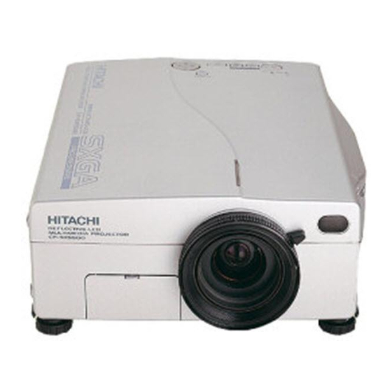
Multimedia LCD Projector
November 2001 Digital Media Systems Division
YK
CP-SX5500W
Caution
ServiceWarning
Contents
8. Connector connection diagram -------------------- 26
9. Wiring diagram ----------------------------------------- 27
10.Basic circuit diagram---------------------------------- 29
11.Disassembly diagram--------------------------------- 81
12.Replacement parts list ------------------------------- 82
13.RS-232C communication ---------------------------- 83
No.0517E
Advertisement
Table of Contents

Related Manuals for Hitachi CP-SX5500W


Summary of Contents for Hitachi CP-SX5500W
-
Page 1: Table Of Contents
Be sure to read this manual before servicing. To assure safety from fi re, electric shock, injury, harmful radiation and materials, various measures are provided in this Hitachi Multimedia LCD Projector. Be sure to read cautionary items described in the manual to maintain safety before servicing. -
Page 2: Features
CP-SX5500W 1. Features 0.9 inches reflecting type liquid crystal panel use. High brightness, High resolution. RS-232C communication. Complies with VESA DDC1/2B specifications. Right and left reversal, vertical reversal function. 2. Specifications Driver built-in type active matrix Drive system Liquid crystal Panel size 0.9 inches... -
Page 3: Names Of Each Part
CP-SX5500W 3. Names of each part Parts names KEYSTONE TEMP Indicator KEYSTONE Button LAMP TEMP LAMP Indicator MENU Button INPUT SELECT STANDBY/ON Button STANDBY/ON Indicator) VIDEO RESET MENU STANDBY / ON RESET Button VIDEO Button Control Panel RGB Button Control Panel... - Page 4 CP-SX5500W BLANK Button STANDBY/ON Button LASER Button VIDEO Button RGB Button Disk Pad MOUSE / RIGHT Button Used to operate the Used to click the right mouse shift function and mouse button. left click function. KEYSTONE Button AUTO Button RESET Button...
-
Page 5: Adjustment
CP-SX5500W 4. Adjustment 4-1 Before adjusting 1. Before starting adjustment, warm up the projector 4. Perform all adjustments from the Adjustment menu. for about 30 minutes.(Blank white) Perform the following operations to display the 2. Set Zoom Wide to Max. And project an image a Adjustment menu. - Page 6 CP-SX5500W 4-4 CYCLE OFFSET adjustment (vertical stripe adjustment) Signals for internal adjustment Adjustment procedure 1. Make this adjustment after completing the adjustment in 4-3 Flicker adjustment. 2. Use DAC-P - CYCLE - R: in the Adjustment menu to adjust so that the vertical lines spaced every 12...
- Page 7 CP-SX5500W 9. Adjust Gamma, 86%, and G: in the Adjust menu so 17. Adjust Gamma, 86%, R: and B: so that the color that luminance (Y) at the center of the screen is coordinates (x, y) at the center of the screen take adjusted as follows.
- Page 8 CP-SX5500W 4-6 Color uniformity adjustment Preparations 1. Perform these adjustments after the white balance 6. To temporarily turn correction off, place the cursor adjustment described in Section 4-5. on “ON” in the Adjust Tone menu and press the [ 2. Make a color uniformity adjustment for the key.
- Page 9 CP-SX5500W Adjustment procedure 1 (when a color differential meter is used) 1. First adjust [MID] tone [G:]. 9. Similarly, measure adjustment points [No.3] to 2. Select adjustment point [No.2][G:]. [No.17] and adjust their color coordinates starting in order from the small number points.
- Page 10 CP-SX5500W Adjustment procedure 2 (visual inspection) 1. First adjust [MIN] tone [G:]. 6. View measurement points [No.2], [No.3], [No.10] 2. Select [No.2] [G:]. and [No.11]. Adjust the [R] and [B] of each measurement point so that they have the same...
-
Page 11: Troubleshooting
CP-SX5500W 5. Troubleshooting Check points at trouble shooting... - Page 12 CP-SX5500W Power can not be turned on voltage input at Disconnect pins TSW form Power unit 5 7 13 Open EPOW on the PWB ass'y (circuit). And check MAIN at standby TSW short or mode? open? : +12.5V : +16.5V Short : +6.6V...
- Page 13 CP-SX5500W Lamp does not light What is the state of Light Light Change the lamp. Lamp LAMP indicator Does lamp light? during operation? Not light Not light Is the voltage at the of EFN1 on the PWB Power unit (ballast) ass'y MAIN fixed to "H"...
- Page 14 CP-SX5500W Picture is not displayed only when the RGB signal is input Check at operating mode Are signal input at each pin of PWB ass'y SIGNAL EMS1 on the PWB ass'y MAIN? (R185) : R signal (R188) : G signal...
- Page 15 CP-SX5500W No sound Check at operating mode Are the signals input at each pin of EMS2 on the PWB ass'y MAIN? PWB ass'y VIDEO : Audio (L) : Audio (R) PWB ass'y MAIN Speaker Can not control mouse. Can not control RS-232C.
-
Page 16: Service Points
CP-SX5500W 6. Service points Cautions when removing the PWB Ass'y MAIN When removing the PWB Ass'y MAIN, there is danger of damaging the connector connecting cables. 1) Disconnect 9 cables and remove 5 screws. Take care not to touch the terminals when connecting or disconnecting the panel FPC. - Page 17 CP-SX5500W DIRECTION OF EARTH METAL DIRECTION OF CONNECTOR WIRE TERMINAL EARTH METAL Attach the metal of the ground wire and connector wire terminal so it EARTH METAL faces in the indicated direction as CONNECTOR FOR GROUND shown. CONNECTION TO OPT UNIT To remove the upper case, completely loosen the screws.
- Page 18 CP-SX5500W Cautions when assembling and disassembling the CASE BOTTOM CASE Attache the “LAMP DOOR” LAST. (When the unit is re-assembled the unit is repaired.) First of all, Remove the “LAMP DOOR”. (When the unit is disassembled.) LAMP DOOR Cautions when assembling the PWB ass’y MAIN Before assembling the PWB ass’y MAIN, Please check that the UPPER FIX METAL is located in this position.
- Page 19 Therefore, regarding these parts, you can either replace part , LCD / Lens Prism Ass'y, or send the whole unit LCD / Lens Prism Ass'y back to Hitachi, where we will replace the malfunctioning part, recondition the device and send it back to you. In that case please contact our distributor.
- Page 20 CP-SX5500W Lamp HIGH VOLTAGE HIGH TEMPERATURE HIGH PRESSURE Option Lamp: DT00421 Before replacing the lamp, switch power OFF, remove the power cord from the power outlet, and wait approximately 45 minutes until the lamp has cooled. The lamp may explode if handled at high temperatures.
- Page 21 CP-SX5500W Replacing the Lamp 1. Switch the projector OFF, remove the power cord from the power outlet, and wait at least 45 minutes for the unit to cool. 2. Prepare a new lamp. 3. Check that the projector has cooled suffi ciently, and gently turn it upside down.
- Page 22 CP-SX5500W Air Filter Replacing the Air Filter CP-SX5500 Replace the air filter if contamination cannot be removed, or if it Filter box is damaged. 1. Remove the filter lid. 2. Pull and remove the old filter from the filter box.
- Page 23 CP-SX5500W Message table OSD Message The messages as described below may appear on the screen at power ON. Take the appropriate measures when such a message appears. Message Contents The message shown at left appears after the lamp has been used for more than 1300 hours.
- Page 24 CP-SX5500W Indicators Message The POWER indicator, LAMP indicator, and TEMP indicator are lit and blank as follows. Take the appropriate measures. STANDBY/ON LAMP TEMP Contents indicator indicator indicator Lights Turns off Turns off The Standby mode has been set. orange Blinks Turns off Turns off Warming up.
-
Page 25: Block Diagram
CP-SX5500W 7. Block diagram... -
Page 26: Connector Connection Diagram
CP-SX5500W 8. Connector connection diagram... -
Page 27: Wiring Diagram
CP-SX5500W 9. Wiring diagram... - Page 28 CP-SX5500W...
-
Page 29: Basic Circuit Diagram
CP-SX5500W 10. Basic circuit diagram Parts with hatching are not mounted. POWER UNIT (BALLAST)(C5SXR) - Page 30 CP-SX5500W CP-SX5500W POWER UNIT (CIRCUIT)(C5SXR)
- Page 31 CP-SX5500W PWB assembly SWITCH PWB assembly FAN (C5SXR)
- Page 32 CP-SX5500W (female) (female) (female) PWB assembly RGB 1 (C5SXR)
- Page 33 CP-SX5500W (male) PWB assembly RGB 2 (C5SXR)
- Page 34 CP-SX5500W PWB assembly VIDEO 1 (C5SXR)
- Page 35 CP-SX5500W PWB assembly VIDEO 2 (C5SXR)
- Page 36 CP-SX5500W PWB assembly VIDEO 3 (C5SXR)
- Page 37 CP-SX5500W PWB assembly MAIN 1 (C5SXR)
- Page 38 CP-SX5500W PWB assembly MAIN 2 (C5SXR)
- Page 39 CP-SX5500W PWB assembly MAIN 3 (C5SXR)
- Page 40 CP-SX5500W PWB assembly MAIN 4 (C5SXR)
- Page 41 CP-SX5500W PWB assembly MAIN 5 (C5SXR)
- Page 42 CP-SX5500W serial parallel PWB assembly MAIN 6 (C5SXR)
- Page 43 CP-SX5500W D A T A 1 D C L K 2 PWB assembly MAIN 7 (C5SXR)
- Page 44 CP-SX5500W PWB assembly MAIN 8 (C5SXR)
- Page 45 CP-SX5500W PWB assembly MAIN 9 (C5SXR)
- Page 46 CP-SX5500W SD 63:0 PWB assembly MAIN 10 (C5SXR)
- Page 47 CP-SX5500W PWB assembly MAIN 11 (C5SXR)
- Page 48 CP-SX5500W PWB assembly MAIN 12 (C5SXR)
- Page 49 CP-SX5500W PWB assembly MAIN 13 (C5SXR)
- Page 50 CP-SX5500W PWB assembly MAIN 14 (C5SXR)
- Page 51 CP-SX5500W PWB assembly MAIN 15 (C5SXR)
- Page 52 CP-SX5500W PWB assembly MAIN 16 (C5SXR)
- Page 53 CP-SX5500W PWB assembly MAIN 17 (C5SXR)
- Page 54 CP-SX5500W ( for DVI ) PWB assembly MAIN 18 (C5SXR)
-
Page 55: Disassembly Diagram
CP-SX5500W 11. Disassembly diagram M : Meter screw T : Tapping screw M3x10 with lock washer M3x12 M3x6 with lock washer (Note) Please remove slowly, Panel cushion is broken. M3x30 P3x12 M3x35 M3x25 M3x8(A) M3x8(A) M3x8(A) Remove this first. M3x8(A) -
Page 56: Replacement Parts List
CP-SX5500W 12. Replacement Parts list PRODUCT SAFETY NOTE : Components marked with a have special characteristics important to safety. Before replacing any of there components, read carefully, the PRODUCT SAFETY NOTICE of this Service Manual. Don't degrade the safety of the receiver through improper servicing. -
Page 57: Rs-232C Communication
CP-SX5500W 13. RS-232C communication (1) Turn off the projector and computer power supplies and connect with the RS-232C cable. (2) Turn on the computer power supply and, after the computer has started up, turn on the projector power supply. RS-232C terminal... - Page 58 CP-SX5500W Requesting projector status (Get command) (1) Send the request code Header + Command data (‘02H’+‘00H’+ type (2 bytes) +‘00H’+‘00H’) from the computer to the projector. (2) The projector returns the response code ‘1DH’+ data (2 bytes) to the computer.
- Page 59 CP-SX5500W Command data chart Command data Names Operation type Header Action Type Setting code BE EF 06 00 3B D3 01 00 00 30 00 00 Orange BE EF 06 00 AB D2 01 00 00 30 01 00 Green...
- Page 60 CP-SX5500W Command data chart Command data Names Operation type Header Action Type Setting code BE EF 06 00 7C D2 02 00 07 30 00 00 Magnify Increment BE EF 06 00 1A D2 04 00 07 30 00 00...
- Page 61 CP-SX5500W Command data chart Command data Names Operation type Header Action Type Setting code Normal BE EF 06 00 46 D3 01 00 02 20 00 00 Mute Mute BE EF 06 00 D6 D2 01 00 02 20 01 00...
- Page 62 CP-SX5500W Command data chart Command data Names Operation type Header Action Type Setting code BE EF 06 00 F1 72 02 00 01 22 00 00 Sharpness Increment BE EF 06 00 97 72 04 00 01 22 00 00...
- Page 63 CP-SX5500W Command data chart Command data Names Operation type Header Action Type Setting code Upper left BE EF 06 00 02 23 01 00 01 23 00 00 Upper right BE EF 06 00 92 22 01 00 01 23...
- Page 64 CP-SX5500W YK No.0517E Digtal Media System Division QR50701 Printed in Japan (S)