Advertisement
Quick Links
TABLE OF CONTENTS
1 Warning -------------------------------------------------------------- 2
2 Specifications ----------------------------------------------------- 2
3 Troubleshooting Guide ----------------------------------------- 3
4 Disassembly and Assembly Instructions ---------------- 4
5 Wiring Connection Diagram ---------------------------------- 8
6 Schematic Diagram ---------------------------------------------- 9
7 Exploded View and Replacement Parts List -----------10
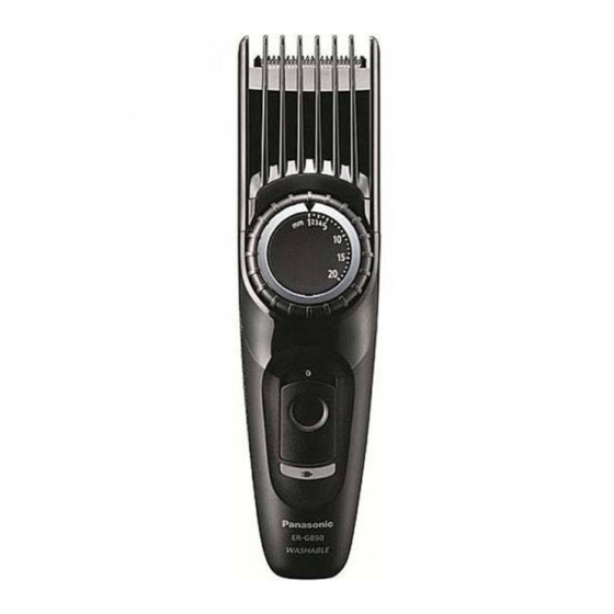
AC/Rechargeable Hair Clipper
Model No.
Asia
Middle East
PAGE
© Panasonic Electric Works Co., Ltd. 2010.
All rights reserved. Unauthorized copying and distri-
bution is a violation of law.
Order Number SD1010A67CE
ER-GB50
PAGE
Advertisement

Summary of Contents for Panasonic ER-GB50
-
Page 1: Table Of Contents
4 Disassembly and Assembly Instructions ---------------- 4 5 Wiring Connection Diagram ---------------------------------- 8 6 Schematic Diagram ---------------------------------------------- 9 7 Exploded View and Replacement Parts List -----------10 © Panasonic Electric Works Co., Ltd. 2010. All rights reserved. Unauthorized copying and distri- bution is a violation of law. -
Page 2: Warning
1 Warning Caution: • Pb free solder has a higher melting point that standard solder; Typicall the melting point is 50 - 70°F (30 - 40°C) higher. Please use a soldering iron with temperature control and adjust it to 750 ± 20°F (400 ± 10°C). In case of using high temperature solder- ing iron, please be careful not to heat too long. -
Page 3: Troubleshooting Guide
3 Troubleshooting Guide... -
Page 4: Disassembly And Assembly Instructions
4 Disassembly and Assembly Instructions 4.1. Disassembly Instructions 1. Remove the blade. 2. Insert a slotted screwdriver into the slit of dial cover firmly and raise it with the driver. NOTE : Make sure there is NO scratch or damage on the parts. - Page 5 4. Loosen two screws. 5. Remove the housing C. 6. Loosen a screw. 7. Insert a slotted screwdriver under the front panel, then raise the front panel with the driver slightly.
- Page 6 8. Loosen 8 screws and remove the housing A. 9. Loosen 2 screws and remove the module assembly with rechargeable battery first, then remove the motor holder.
- Page 7 4.2. Assembly Instructions For assembly, reverse the order of disassembly. 1. Insert the rechargeable battery into the battery holder. NOTE: Make sure to attach the washer and O-ring to the bat- tery terminal. The O-ring for the battery terminal is the thickest.
-
Page 8: Wiring Connection Diagram
6. Set the housing C. NOTE: Make sure to set the rack. Insert the hook of housing C under the front panel first. 7. Fix the dial and the dial mounting base by a screw. NOTE: Make sure to set the slit at left side. Apply the grease (G741S) on the gear of dial. -
Page 9: Schematic Diagram
6 Schematic Diagram... -
Page 10: Exploded View And Replacement Parts List
7 Exploded View and Replacement Parts List Model No. : ER-GB50 Exploded View... - Page 11 Model No. : ER-GB50 Parts List Ref. Safety Part No. Part Name & Description Q'ty Remarks WERGB50K7458 COMB ATTACHMENT 1 (1-20mm) WERGB50K7468 DETAIL TRIMMING ATTACHMENT WER9605Y BLADE BLOCK WERGB50S3108 DIAL COVER WES7023L9008 TAPPING SCREW 1 (M2-6) WER217D1477 DIAL MOUNTING BASE...


