
Related Manuals for Acer AL1703


Summary of Contents for Acer AL1703
- Page 1 All manuals and user guides at all-guides.com Acer AL1703 Service Guide Service guide files and updates are available on the CSD web : for more information, Please refer to http: csd.acer.com.tw...
- Page 2 All manuals and user guides at all-guides.com...
- Page 3 All manuals and user guides at all-guides.com...
- Page 4 All manuals and user guides at all-guides.com...
- Page 5 All manuals and user guides at all-guides.com...
- Page 6 All manuals and user guides at all-guides.com...
-
Page 7: Table Of Contents
All manuals and user guides at all-guides.com Table of Contents Chapter 1 Monitor Features … … … … … … … … … … … … … … .… … … . 8 1.1 Test Conditions… … … … … … … … … … … … … … … .… … … … 8 1.2 Features…... -
Page 8: Chapter 1 Monitor Features
All manuals and user guides at all-guides.com Monitor Features Chapter 1 Test Conditions Item Condition Temperature Normal room temperature (25± 2℃) Humidity 50± 10% AC input voltage 100V± 2V, 120± 2V, 60Hz / 240± 2V, 50Hz Brightness Maximum with OSD setting Contrast Middle with OSD setting Resolution setting... -
Page 9: Lcd Panel Specification
All manuals and user guides at all-guides.com 1.3 LCD panel Specification Item Specification Active Area 337.9 (H) x 270.34 (V) (17.0” diagonal) Driver Element a-si TFT Active Matrix Pixel Number 1280 x R.G.B. x 1024 Pixel Pitch 0.264 (H) x 0.264 (V) Pixel Arrangement RGB Vertical Stripe Display Color... - Page 10 All manuals and user guides at all-guides.com Definition of Contrast Ratio (CR): The contrast ratio can be calculated by the following expression and figure below. Contrast Ratio (CR) = L255 / L0 L255: Luminance of gray level 255 L 0: Luminance of gray level 0 CR = CR (5) CR (X) is corresponding to the Contrast Ratio of the point X at Figure in Note (5).
- Page 11 All manuals and user guides at all-guides.com Measurement Setup: The LCD module should be stabilized at given temperature for 20 minutes to avoid abrupt temperature change during measuring. In order to stabilize the luminance, the measurement should be executed after lighting Backlight for 20 minutes in a windless room.
-
Page 12: Chapter 2 Operating Instructions
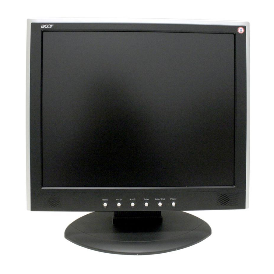
All manuals and user guides at all-guides.com OPERATING INSTRUCTIONS Chapter 2 2.1 Function Name Front 2.1.1 Descriptions Power Switch Power on / Power off Green/Blue Normal operation Orange Power Management Indicator Power off AUTO/ EXIT Adjust Clock, Phase, H Position and V Position automatically / Exit Turbo Brightness Switch TURBO A170E1- T01... - Page 13 All manuals and user guides at all-guides.com Back 2.1.2 Name Descriptions AUDIO-IN d=3.5mm stereo mini Jack VGA-IN D-sub mini 15pin Connector DC-IN DC Power Jack, d=2.0mm. Lock hole Kinglock...
-
Page 14: Osd Menu Description
All manuals and user guides at all-guides.com 2.2 OSD Menu Description 1. Power : Press this key to control power ON/OFF of the Monitor. Green: normal display. Orange flicker: no signal input. Orange: power off. 2. Auto/Exit : When the input signal source is PC, used to execute auto adjustment 3. -
Page 15: Osd Control
All manuals and user guides at all-guides.com 2.3 OSD Control Press the “Menu” button to start the OSD feature. Click the “+” or “-“ button to select the function to be adjusted. Click the “Menu” button to access into the function to be adjusted. Click the “+”... -
Page 16: Osd Function Definition
All manuals and user guides at all-guides.com 2.5 OSD Function Definition Description Primary Secondary Directory Directory Adjust the brightness of the screen. Image Brightness Contrast Adjust the contrast of the image. Clock Adjust the clock pulse of the image. Phase Adjust the focus of the image. -
Page 17: Plug And Play
All manuals and user guides at all-guides.com 2.6 Plug and Play The new VESA Plug and Play function is used which eliminates the complicated and time-consuming installation process. You can use the Plug and Play system without encountering usual installation problems. Your computer system can easily i d entify and automatically adjust the monitor. -
Page 18: Chapter 3 Machine Disassembly And Assembly
All manuals and user guides at all-guides.com MACHINE DISASSEMBLY Chapter 3 AND ASSEMBLY 3.1 Disassembly Procedures Picture Description Push the hooks and stand bottom away Remove Hinge Cover Loosen and remove 6 screws to remove Stand Assy Loose and remove 2 screws. Separate Bezel hooks to take Bezel and Rear Cover apart. - Page 19 All manuals and user guides at all-guides.com Remove FFC Loose and remove screw and remove Cover-FFC Loose and remove 2 screws Loose and remove 5 screws Remove the Cover of X-PCB Remove 4 pieces of Backlight wires. Loose and remove 4 screws Remove Power PCBA...
- Page 20 All manuals and user guides at all-guides.com Remove 2 pieces of FFC from AD PCBA Loose and remove 1 screw Remove AD PCBA Disassembly PCBA complete. Loose and remove 4 crews Lift up LCD module and remove bezel. Remove FFC. Separate both Audio Cable.
-
Page 21: Machine Assembly
All manuals and user guides at all-guides.com Loose and remove 3 screws. Take OSD PCBA apart 3.2 Assembly Procedures Place OSD PCBA. Fasten 3 screws Insert Audit Cable to connectors of OSD PCBA Bezel assembly complete. Insert FFC. - Page 22 All manuals and user guides at all-guides.com Place LCD module. Fasten 4 fixed screws Insert new AD PCBA Insert 2 pieces of FFC to AD PCBA . Insert new Power PCBA Fasten 4 fixed screws of Power PCBA Insert 4 pieces of Backlight wires Fasten 5 screws...
- Page 23 All manuals and user guides at all-guides.com Join the cover hooks of X-PCB and fasten the screw Fasten 2 screws Place Cover-FFC and fasten screw Insert FFC Attach the Tinfoil Place Rear Cover Join hooks of Rear Cover with Bezel Fasten 2 screws...
- Page 24 All manuals and user guides at all-guides.com Place Stand Assy. Fasten 6 screws Insert Stand Cover Have the hook latched...
-
Page 25: Chapter 4 Troubleshooting
All manuals and user guides at all-guides.com Troubleshooting Chapter 4 4.1 Abnormal Display Troubleshooting... - Page 26 All manuals and user guides at all-guides.com...
-
Page 27: Abnormal (On/Off, Lcd Display, K/B) Troubleshooting
All manuals and user guides at all-guides.com 4.2 Abnormal (ON/OFF, LCD display, Keyboard ) Troubleshooting... -
Page 28: Abnormal (Bios, Osd, Other Display) Troubleshooting
All manuals and user guides at all-guides.com 4.3 Abnormal (BIOS, OSD, Other Display ) Troubleshooting... -
Page 29: Audio Abnormal
All manuals and user guides at all-guides.com 4.4 Audio Abnormal Troubleshooting... -
Page 30: Chapter 5 Connector Information
All manuals and user guides at all-guides.com Connector Information Chapter 5 5.1 Function Block Diagram OSD Key Speaker Audio Audio In 3.3V DVI-D Main Digital Video D-sub Signal Analog Video DC/D DC-19V Inverter DC -19V Backlight... -
Page 31: Connector Location
All manuals and user guides at all-guides.com 5.2 Connector Location... -
Page 32: D-Sub Mini 15Pin Connector
All manuals and user guides at all-guides.com 5.3 D-sub Mini 15pin Connector Pin No. Pin Function Pin No. Pin Function Red video input Green video input Ground Blue video input No connection DDC data Ground Horizontal sync (Composite sync) Red video ground Vertical sync Green video ground DDC clock... - Page 33 All manuals and user guides at all-guides.com 5.6.2 CN-A1 Pin Assignment Pin No. Symbol Description VCOM PANEL COMMOM VOLTAGE VCOM PANEL COMMOM VOLTAGE VCOM PANEL COMMOM VOLTAGE VCOM PANEL COMMOM VOLTAGE GROUND ESTH EVEN PATH STAR PULSE GROUND EB2P EVEN PATH BLUE DATA BIT EB2N EVEN PATH BLUE DATA BIT EB1P...
- Page 34 All manuals and user guides at all-guides.com GROUND ER2P EVEN PATH RED DATA BIT ER2N EVEN PATH RED DATA BIT ER1P EVEN PATH RED DATA BIT ER1N EVEN PATH RED DATA BIT ER0P EVEN PATH RED DATA BIT ER0N EVEN PATH RED DATA BIT 5.6.3 CN-A2 Pin Assignment Pin No.
- Page 35 All manuals and user guides at all-guides.com OCLKP ODD PATH CLOCK OCLKN ODD PATH CLOCK GROUND DATA LATCH POLARITH INVERTING GROUND OR2P ODD PATH RED DATA BIT OR2N ODD PATH RED DATA BIT OR1P ODD PATH RED DATA BIT OR1N ODD PATH RED DATA BIT OR0P ODD PATH RED DATA BIT...
- Page 36 All manuals and user guides at all-guides.com 5.6.5 CN-E Pin Assignment Pin No. Symbol Description RED INPUT GREEN INPUT BLUE INPUT GROUND GROUND RED INPUT GROUND GREEN INPUT GROUND BLUE INPUT GROUND VGA_5V VGA INPUT 5V GROUND GROUND VGA_SDA VGA_HS H-SYNC VGA_VS V-SYNC...
-
Page 37: Chapter 6 Fru
FUNCTION PCBA For A170E1- 35A17K012 BUTTON T,A170E1-H01-K BOARD INVERTER DC/AC Inverter,TWS- 2714000012 BOARD 444- 957,2560V(min)/5mA(typ Main Board AL1703 MAINBOARD 35A17S022 (FIRMWARE CONTROL BOARD) CABLES MAIN BOARD CABLE - 3241702002 FFC 55*23MM CABLE FUNCTION BUTTON 3241700001 BOARD CABLE - FFC 180MM... - Page 38 All manuals and user guides at all-guides.com AUDIO 18AWG,180cm,Black,JC 32F2818004 CABLE MONITOR 30AWG,180cm,Black,JC 32F3018003 CABLE Picture Part name Description Vendor Part No. STAND ABS, Black 40A1792211 BASE Bezel Assy 40A1729245 FRONT BEZEL LCD BACK Rear Assy 40A1799909 COVER LCD STAND Stand Hinge Assy, 40A1799217 NECK...
- Page 39 All manuals and user guides at all-guides.com MAINBOAR Cover_pcb_ad,D-Sub 41A1799107 D COVER Only Cover-FFC 41A1799102 COVER...
- Page 40 All manuals and user guides at all-guides.com...
-
Page 41: Chapter 7 Schematic Diagram
All manuals and user guides at all-guides.com Schematic Diagram Chapter 7 Main Board... - Page 42 All manuals and user guides at all-guides.com...
- Page 43 VPLL VDVI VDPLL All manuals and user guides at all-guides.com RA[0..5] RA[0..5] RIN0 RA1P GNDR GNDR RIN0M RA1N VGA_5V GIN0 RA2P GNDG GNDG GIN0M RA2N SOGIN0 RA3P DDC_CLK DDC_CLK BIN0 RA3N GA[0..5] DDC_DAT GNDB DDC_DAT GNDB BIN0M GA[0..5] ST_DET1 HSYNC ST_DET1 HSYNC HSYNC0...
- Page 44 All manuals and user guides at all-guides.com V33D1 V33D1 2101117STS 2101117STS V33D 0805/42 0805/42 2,3,4,5,8 V33D VI(5V) VO(3.3V) VO(3.3V) C108 C108 C109 C109 C110 C110 C111 C111 (Digital VCC) 0603/0.1u/25V 0603/0.1u/25V 0603/0.1u/25V 0603/0.1u/25V V33D 1206/22U/10V/Y5V 1206/22U/10V/Y5V 1206/22U/10V/Y5V 1206/22U/10V/Y5V V33A1 V33A1 2101117STS 2101117STS V33A...