Table of Contents
Advertisement
OWNER'S MANUAL
HEAT PUMP
WATER HEATER
Read this owner's manual thoroughly before operating the
appliance and keep it handy for reference at all times.
Original instruction
EN ENGLISH
DE DEUSTSCH
MFL71409202
Rev.02_112320
FR FRANÇAIS
IT
ITALIANO
Copyright © 2020 LG Electronics Inc. All Rights Reserved.
ES ESPAÑOL
PL
POLSKI
www.lg.com
Advertisement
Table of Contents

Related Manuals for LG WH20S F5


Summary of Contents for LG WH20S F5
- Page 1 Read this owner’s manual thoroughly before operating the appliance and keep it handy for reference at all times. Original instruction EN ENGLISH FR FRANÇAIS ES ESPAÑOL DE DEUSTSCH ITALIANO POLSKI www.lg.com MFL71409202 Rev.02_112320 Copyright © 2020 LG Electronics Inc. All Rights Reserved.
-
Page 2: Table Of Contents
Safety Controls.......................21 Insulation Blanket Kits....................21 Installation Checklist ....................22 OPERATION ..............23 Using Basic Control....................23 SMART FUNCTIONS .............25 LG ThinQ Application .....................25 MAINTENANCE .............27 Draining and Flushing the Water Heater ..............27 T&P Relief Valve Maintenance................28 Air Filter Maintenance ....................28 Condensate Drain Maintenance................29 Shut-down for an Extended Period ................29... -
Page 3: Safety Instructions
SAFETY INSTRUCTIONS Your safety and the safety of others are very important. We have provided many important safety messages in this manual and on your appliance. Always read and follow all safety messages. This is the safety alert symbol. This symbol alerts you to potential hazards that can kill or injure you and others. -
Page 4: Safety Precaution
WARNING To reduce the risk of explosion, fire, death, electric shock, injury or scalding to persons, instructions in this manual must be followed. Be sure to fully understand the user’s manual before you install and operate this appliance. If you have any difficulty in understanding or following the instructions in this manual, or have any questions, contact an authorized service center or the local electric utility. - Page 5 For determining the proper water temperature for your home, refer to the chart below. Temperature Time to Produce a Serious Burn 49 °C More than 5 minutes 52 °C 1 ½ to 2 minutes 54 °C About 30 seconds 57 °C About 10 seconds 60 °C Less than 5 seconds...
- Page 6 Local Installation Regulations This appliance must be installed accordance with instructions of this manual, national regulations, and any regulations issued by local authorities and public health bodies. IMPORTANT SAFETY INSTRUCTIONS WARNING To reduce the risk of explosion, fire, death, electric shock, scalding or injury to persons when using this product, follow basic precautions, including the following: Children in the Household:...
- Page 7 Installation • To reduce the risk of severe injury or death, follow all installation instructions. • Be sure your appliance is properly installed in compliance with local codes and the provided installation instructions. • Do not replace any part of your water heater and use only original accessories and spare part unless it is specifically recommended in this manual.
- Page 8 • This appliance must be positioned near to an electrical power supply. Use a power supply of 1.5 mm or more in the nominal cross-sectional area • Do not install the water heater on an unstable surface or in a place where there is danger of it falling.
- Page 9 • Feel water before bathing or showering. • Even at 50 °C, hot water can scald. • Do not block the inlet or outlet of air flow. • Never touch, operate, or repair the water heater with wet hands. • Do not leave flammable substances such as gasoline, benzene, or thinner near the water heater.
- Page 10 • Disconnect this appliance from the power supply before cleaning and attempting any user maintenance. • Before draining water heater, turn off the power to product. • Do not turn on the electrical power to the water heater unless the tank is completely full of water. Technical Safety •...
- Page 11 • Install the product so that the noise or hot wind from the appliance may not cause any damage to the neighbors. Otherwise, it may cause dispute with the neighbors. • Install the drain hose properly for the smooth drainage of water condensation.
-
Page 12: Installation
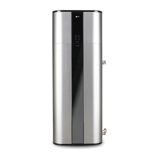
INSTALLATION Parts and Functions Top cover Air intake vents Junction box Air filter Front panel Display decor / Control panel Upper element cover Front decor Lower element cover Heating element Opening for drain valve Water inlet Opening for T&P relief valve Water outlet 9 10 Condensate drain... -
Page 13: Installation Tools
Installation Tools Figure Name Figure Name Screw driver Teflon tape Spanner Level Multi-meter Accessories Included Accessories: Figure Name Figure Name Drain valve T&P relief valve Recommended Accessories: Figure Name Figure Name Thermal Drain pan expansion tank Pressure Thermostatic reducing valve mixing valve... -
Page 14: Installation Instructions
Installation Instructions Ceiling 0.5 m Minimum clearance for installation or service. Air filter Display Secondary condensate Primary condensate drain line (1/2” PVC) drain line (3/4” PVC) Hot water outlet T&P relief valve and discharge line Flexible connection recommended Flexible connection recommended Heat trap Min. -
Page 15: Select The Best Location
Select the best Location Minimum Clearances Minimum room size: NOTE 20 m • Installation in a confined space without 0.5 m proper ventilation will lead to higher power consumption. • Auxiliary drain pan MUST be installed in 0.45 m 0.15 m compliance with local codes. -
Page 16: Unpacking And Removing Shipping Bolts
This will cause the relief valve to open during Unpacking and Removing each heating cycle. We recommend installing Shipping Bolts an expansion tank to control thermal expansion. NOTE • Accessories (drain valve and T&P relief Connect the thermal expansion tank to the valve) are attached on pallet. - Page 17 Connecting T&P Relief Valve Attach the discharge pipe to outlet of the T&P relief valve. The discharge pipe must Discharge Pipe pitch downward from the valve to allow complete drainage of both T&P relief valve and discharge pipe. WARNING The pressure rating of the relief valve must not exceed 1 MPa, the maximum working pressure of the water heater as specified on the data plate.
-
Page 18: Installing Condensate Drain Lines
Installing Condensate Drain Using an approved sealant, insert the PVC pipe into the female end. Condensate Lines drain must be piped to an adequate drain. NOTE • When making drain fitting connections to the drain tubing, DO NOT overtighten. Overtightening fittings could crack or damage the condensate drain pan. -
Page 19: Connecting The Water Supply
Connecting the Water Supply For ease of disconnecting the water heater for service or replacement, the installation of unions is recommended on the water NOTE connections. • DO NOT directly solder or braze to hot or cold Install a shut-off valve in the cold water water connections. -
Page 20: Making Electrical Connections
Making Electrical The water heater must be permanently powered by electricity to ensure correct operation of the Connections impressed current titanium anode (ICCP). Do not turn on power until water heater is completely filled. WARNING The appliance can only be connected and operated on a single-phase 230 V AC grid. -
Page 21: Safety Controls
Safety Controls Insulation Blanket Kits External insulation blanket, available to the general public, for water heater is not CAUTION necessary. You must have a qualified person The manufacturer’s warranty does not cover investigate the cause of the high any damage or failure caused by installing or temperature condition and take corrective using any type of unauthorized energy-saving action before placing the water heater in... -
Page 22: Installation Checklist
Installation Checklist Location Sufficient room for air exchange and periodic service. Floor is strong enough to support water heater. Indoor and protected from high corrosive elements. Close to the area of heater water demand. Over 1 °C. Area free of flammable liquids and gases. Drain valve Drain valve properly installed. -
Page 23: Operation
To select the auto mode. To select the turbo mode. To select the Vacation mode. Set schedule mode only in LG ThinQ application. To select the Anti Legionella mode. To set the desired water temperature. To adjust the desired water temperature. - Page 24 • Press and hold Mode button about 3 The vacation duration can be set or modified seconds. between 1 and 90 days via LG ThinQ app. is displayed on the display screen.
-
Page 25: Smart Functions
LG ThinQ • LG ThinQ is not responsible for any network application and register it again. connection problems or any faults, • The application is subject to change for... - Page 26 • If the firewall on your wireless router is the LG ThinQ application. enabled, disable the firewall or add an • Launch the LG ThinQ application and select exception to it. the Smart Diagnosis feature in the menu.
-
Page 27: Maintenance
MAINTENANCE Draining and Flushing the WARNING Water Heater Turn off the power by opening the Minerals contained in tap water can form lime circuit breaker or removing the fuses deposits. Therefore, it is not uncommon that before you perform any maintenance; lime deposits accumulate in the water heater’s otherwise it may cause electrical shock tank. -
Page 28: T&P Relief Valve Maintenance
T&P Relief Valve Air Filter Maintenance Maintenance Clean the air filters when “Air filter check )” alarm appears on the display. DANGER NOTE • The air filter can be broken when it is Before manually operating the relief bended. valve, make sure it will discharge in a •... -
Page 29: Condensate Drain Maintenance
Condensate Drain Shut-down for an Extended Maintenance Period If the water heater will not be used for an Remove the condensate drain lines and extended period of time, turn off the power connections. and water supply to water heater and drain water heater to conserve energy and prevent a build-up of dangerous hydrogen gas. -
Page 30: Troubleshooting
TROUBLESHOOTING Before Calling for Service Please check the following before you contact the service center. If the problem persists, contact your local service center. CAUTION For your safety, do not attempt to repair of electrical wiring, controls, heating elements or other safety devices. Refer repairs to qualified service personnel Problem Possible Causes &... - Page 31 Problem Possible Causes & Corrective Action The heat pump compressor, fan, or EEV valve is running • This is normal Build up of scale or lime deposits on heating elements may cause Noise rumbling noise • Clean or replace the heating elements. This should only be performed by qualified service person.
-
Page 32: Error Code
Error Code Code Contents Corrective Action Operating status Call our Technical Support Ambient Temp sensor is not working. Use Elements Only Center. Clean Condensate drain. Condensate drain is blocked. See “Condensate Drain Use Elements Only Maintenance” section. Call our Technical Support PCB Communication error. -
Page 33: Replacement Parts List
Replacement Parts List Item No. Description Item No. Description Panel Assembly,Front Switch Assembly PCB Assembly,Display Pan Assembly,Drain Front decor (Cover,Terminal) Compressor Set,China Cover Assembly,Top Damper,Compressor Filter Assembly,Air Cleaner Tube Assembly,Reverse Cover Assembly,Control Coil,Expansion PCB Assembly,Power Tube Assembly,Expansion PCB Assembly,Main Tube Assembly,Evaporator(Out) PCB Assembly,Module Tube Assembly,Connector Transformer,Reactor... - Page 34 CAUTION For your safety, Do not attempt to repair electronic controls, electrical wiring, heat pump, heating elements or other safety devices by yourself. Refer repair to authorized service center. NOTE • Check the water heater’s rating plate on the unit for the acceptable voltage and wattage. Replacement parts can be ordered through the distributor or store where the heater was purchased.
-
Page 35: Technical Specification
Technical specification Description Unit WH20S F5 WH27S F5 Tank Capacity Dimension (Width x Height x Depth) 580 x 1625 x 582 580 x 2008 x 582 Weight empty Diameter of water connections G 3/4” Diameter of condensate drainage connections 3/4” 1/2”...