
Related Manuals for Acer AL2021


Summary of Contents for Acer AL2021
- Page 1 All manuals and user guides at all-guides.com Acer AL2021 Service Guide Service guide files and updates are available on the CSD web: for more information, Please refer to http://csd.acer.com.tw/ - 1 -...
- Page 2 “as is ”. Should the programs prove defective following their purchase, the buyer (and not Acer Incorporated, its distributor, of its dealer) assumes the entire cost of all necessary servicing, repair, and any incidental or consequential damages resulting from any defect in the software.
- Page 3 All manuals and user guides at all-guides.com Conventions The following conventions are used in this manual: Screen messages Denotes actual messages that appear on screen Note Gives bits and pieces of additional information related to the current topic. Warning Alerts you to any damage that might result from doing or not doing specific actions.
- Page 4 DIFFERENT part number code to those given in the FRU list of this printed Service Guide. You MUST use the list provided by your regional Acer office to order FRU parts for repair and Service of customer machines.
- Page 5 All manuals and user guides at all-guides.com WARNING: (FOR FCC CERTIFIED MODELS) NOTE: this equipment has been tested and found to comply with the limits for a Class B digital device, pursuant to Part 15 of the FCC Rules. These limits are designed to provide reasonable protection against harmful interference in a residential installation.
- Page 6 All manuals and user guides at all-guides.com PRECAUTIONS Do not use the monitor near water, e.g. near a bathtub, washbowl, kitchen sink, laundry tub, Swimming pool or in a wet basement. Do not place the monitor on an unstable trolley, stand, or table. If the monitor falls, it can injure a person and cause serious damage to the appliance.
- Page 7 All manuals and user guides at all-guides.com SPECIAL NOTES ON LCD MONITORS The following symptoms are normal with LCD monitor and do not indicate a problem. NOTES Due to the nature of the fluorescent light, the screen may flicker during initial use. Turn off the Power Switch and then turn it on again to make sure the flicker disappears.
- Page 8 All manuals and user guides at all-guides.com Table of contents Chapter 1 MONITOR FEATURE ………………………………………………………….9 Chapter 2 OPERATING INSTRUTION …………………………………………………….15 Chapter 3 Machine assembly ……………………………………………………………22 Chapter 4 TROBLE SHOOTING ………………………………………………………….32 Chapter 5 CONNECTOR INFORMATION ……………………………………………….34 Chapter 6 FRU LIST ………………………………………………………………………..36 Chapter 7 SCHEMATIC DIAGRAM …………………………………………………………40 - 8 -...
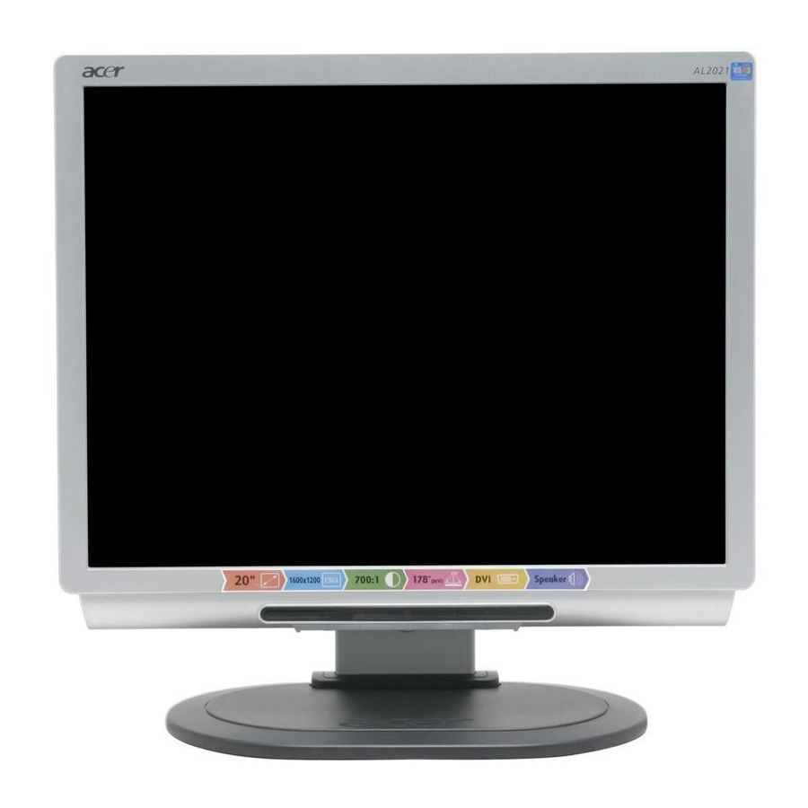
- Page 9 All manuals and user guides at all-guides.com Chapter 1 Monitor Feature Driving system TFT Color LCD Size 20.1" Pixel pitch 0.255 mm Viewable angle 85(H) x 85 (V) degree Brightness 250 cd/m2(typ) Contrast Ratio 600:1 (typ) LCD Panel Response time 20ms (Tr+Tf) Video R,G,B Analog...
- Page 10 All manuals and user guides at all-guides.com * Power Switch * MENU/ENTER * >/ Volume * </ Volume Switch * Auto Adjust KEY Function * Contrast/brightness * Focus / Clock * H. / V.Position * COLOR * Language * OSD SETTING : H / V. Position & Timeout * Input Signal Selection * Information * Reset...
- Page 11 All manuals and user guides at all-guides.com PRESET TIMING mode Resolution (KHz) IBM VGA 720 x 400 31.46 VESA 640 x 480 31.46 MAC 13” 640 x 480 VESA 640 x 480 37.86 VESA 640 x 480 37.5 VESA 800 x 600 35.16 VESA 800 x 600...
- Page 12 All manuals and user guides at all-guides.com Monitor Block Diagram +3.3V_ I/O_MALIBU +2.5V_DDR +3.3V_LVDSA +1.8V_DVI +1.8V_ADC +3.3V_PLL POWER SWITCH AIC 1563 (U2) +1.8V_CORE +3.3V_LBADC +3.3V_LVDSB +3.3V_LVDS +3.3V_DVI +3.3V_ADC (U3) +2.5V DIGITAL DDC (U4) +3.3V +12V FROM 24AA02 (U12) (U6) +1.8V POWER BOARD SDA/SCL DVI INPUT...
- Page 13 All manuals and user guides at all-guides.com PCB CONDUCTOR VIEW Main Board - 13 -...
- Page 14 All manuals and user guides at all-guides.com Button Board - 14 -...
- Page 15 All manuals and user guides at all-guides.com Chapter 2 OPERATING INSTRUCTIONS Front Panel Definition This Section defines the front panel User Interface for Led Indictor and Key function. Key Definition: There are five keys defined in this system and described bellows. * Adjusting display settings External Controls Power on/off...
- Page 16 All manuals and user guides at all-guides.com OSD Menu Contrast: This adjusts dark and light shades of color relative to each other to achieve a comfortable contrast. Brightness: This adjusts the brightness of the picture on the screen. Focus: This removes any horizontal distortion and makes the picture clear and sharp.
- Page 17 All manuals and user guides at all-guides.com LANGUAGE: Select the OSD menu language from English-English, Deutsch -German, Espanol-Spanish, 简体中文-Simplified Chinese, 繁體中文 -Traditional Chinese, Francais -French, Italiano -Italian, and 日本語-Japanese. OSD SETTING: H-Position V-Position OSD Timer This changes the position of the OSD window on the screen and staying time.
- Page 18 All manuals and user guides at all-guides.com Exit: Exit from OSD. LED Definition The system equips one dual color (green/amber) led to indict system status and defined as bellows : LED Color System Status Green + Blue System in normal operation mode Amber System in power-saving mode Dark...
- Page 19 All manuals and user guides at all-guides.com AUTO BURN: Use the chip set internal pattern for hot running monitor panel and inverter. AUTO COLOR: Perform Auto Balance measurement by chip set internal signal. And reference these values to initial all other color temperature detail parameters.
- Page 20 All manuals and user guides at all-guides.com LOGO : When the monitor is power on, the LOGO will be showed in the center, and disappear slowly. HOW TO OPTIMIZE THE DOS-MODE Plug and play Plug & play DDC2B feature This monitor is equipped with VESA DDC2B capabilities according to the VESA DDC STANDARD. It allows the monitor to inform the host system of its identity and, depending on the level of DDC used, communicate additional information about its display capabilities.
- Page 21 All manuals and user guides at all-guides.com USING THE RIGHT POWER CORD The accessory power cord for the Northern American region is the wallet plug with NEMA 5-15 style and is UL listed and CSA labeled. The voltage rating for the power cord shall be 125 volt AC. Supplied with units intended for connection to power outlet of personal computer: Please use a cord set consisting of a minimum No.
- Page 22 All manuals and user guides at all-guides.com Chapter 3 Machine Assembly This chapter contains step-by-step procedures on how to assemble the monitor for maintenance and trouble shooting NOTE : 1. The screws for the different components vary in size. During the disassembly process, group the screws with the corresponding to avoid mismatch when putting back the components.
- Page 23 All manuals and user guides at all-guides.com Top View : Side View : ( unit : mm ) - 23 -...
- Page 24 All manuals and user guides at all-guides.com Mechanism exploded drawing - 24 -...
- Page 25 All manuals and user guides at all-guides.com - 25 -...
- Page 26 All manuals and user guides at all-guides.com Picture Description 1.Take a pcs of panel (AA0201U3001, Q’TY:1 ) 2.Stick the Al-foil on CCFT (FBL0T006015 , Q’TY:2 ) 3.Plug the MB-LCD Cable on panel (DD0L0TLC001 ,Q’TY:1) 4. Fix the MB-LCD Cable by yellow tape 1.Take a pcs of FRAME (FAL0T001012 , Q’TY:1 ) 2.
- Page 27 All manuals and user guides at all-guides.com 1.Fix the FRAME & LCD BEZEL SUB ASSY by screws ( MM30030IBJ4 SCREW M3*3-I-NI , Q’TY:4 ) 1. Assemble the INV MODULE & ADP becoming one part . ( AS022180505 INV MODULE(TDK) , Q’TY:1 ) ( AG12046BQ01: ADP 12V 4.6A , Q’TY:1) 1.Fix the INV MODULE &...
- Page 28 All manuals and user guides at all-guides.com 1. Fix the Scalar/B on Frame by screw (MM30040IBJ9 SCREW M3.0*4.0-I(NI) Q’TY:4) 2. Plug-in the Cable MB-LCD (Note: white point face up) 3. Plug in the Cable MB-POWER 1. Fix the PORT BKT on FRAME (FBL0T005019 PORT BKT Q’TY:1) (MM30040IBJ9 SCREW M3.0*4.0-I(NI) Q’TY:2) 1.Stick the MYLAR(POWER) on the...
- Page 29 All manuals and user guides at all-guides.com 1. Fix the INVERTER ESD on FRAME by screws (MM30040IBJ9 SCREW M3.0*4.0-I(NI) Q’TY:2) 1. Fix the SPEAK on LCD BEZEL SUB ASSY (DN0QT390031 SPEAK ASSY Q’TY:1) (MF25080PJB8 SCREW F2.5*8.0-P Q’TY:4) 2. Plug the Connector into Scalar/B 1.
- Page 30 All manuals and user guides at all-guides.com 1. Stick the MYLAR(COVER) on the FRAME ( FCL0T003017 MYLAR(COVER) Q’TY:1) 1. Fix the LCD COVER SUB ASSY by screws . (33L0TLSTN09 LCD COVER SUB ASSY Q’TY:1) ( MF30080BBJ5 SCREW F3.0*8L,B,NI) 1. Put the STAND-ARM into STAND BASE (EAL0T003015 STAND BASE Q’TY:1) (FAL0T005018 STAND-ARM Q’TY:1) 1.
- Page 31 All manuals and user guides at all-guides.com 1. Fix the HINGE-CAP-BTM on the STAND-ARM (EBL0T003016 HINGE-CAP-BTM Q’TY:1) (MF30080BBJ5 SCREW F3.0*8L,B,NI Q’TY:1) 1. Put the HINGE-CAP-TOP on (EBL0T002010 HINGE-CAP-TOP Q’TY:1) 1. Fix the base on the LCD MODULE a)First , Screw the (MM30080BBJ2 SCREW M3.0*8,B(NI) Q’TY:2) on .
- Page 32 All manuals and user guides at all-guides.com Chapter 4 TROUBLE SHOOTING This chapter provides trouble shooting information forAL2010 1. No Power No Power Check Power Button Check cable Change Cable From Main /B(CN1) to Button/B(CN1) Open ? Change Switch or Button board Check power moduleOutput CN1 Pin 1 = on/off (Backlight) ? Pin 2 = Adj (Backlight) ?
- Page 33 All manuals and user guides at all-guides.com 2. No Characters , Missing one Color No Characters Missing one color Check 1.8V , 2.5V Check or Change U6 ,U3, U4 , 3.3V Output ? Check Inverter Check CN2 pin Output Change Inverter And CN2 OK ? From U5 to LCD panel ? Check Panel or Change...
- Page 34 All manuals and user guides at all-guides.com Chapter 5 Connector Information Phonejack stereo PIN1. AC power cord : CEE22 typed connector PIN2. Audio cable PIN3. Audio : Line-in receptacle PhoneJack Stereo Video signal connector 15P Mini D-Sub connector x 1 DB15HD MNEMO SIGNAL...
- Page 35 All manuals and user guides at all-guides.com DVI-D Digital Receptacle Connector x 1 DVI-I The PIN assignment of the 24 pin DVI-D connector / cable is as follows : Signal TMDS data2- (RX2-) TMDS data2+ (RX2+) TMDS data2 shield (GND) DDC clock (SCL) DDC data...
- Page 36 DIFFERENT part number code to those given in the FRU list of this printed Service Guide. You MUST use the local FRU list provided by your regional Acer office to order FRU parts repair and service of customer machines.
- Page 37 All manuals and user guides at all-guides.com Photo Part Name Description Acer Part No. MAINBOARD LOT MB ASSY 55.L06VE.001 ADP 12V 4.6A ADP-58AFA POWER BOARD (DELTA) 55.L06VE.002 90-264V REV1A INV MODULE LOT(12V, INVERTER BOARD(TDK) 55.L06VE.003 V=800V, A1A) BUTTON BOARD LOT BUTTON/B ASSY 55.L06VE.004...
- Page 38 All manuals and user guides at all-guides.com CABLE ASSY LOT POWER CABLE (7P,REV1A) 50.L06VE.005 MB-POWER (7P,REV1A) LOT LCD BEZEL SUB LCD BEZEL ASSY,SILVER 60.L06VE.001 ASSY LOT LCD COVER SUB LCD COVER ASSY, BLACK 60.L06VE.002 ASSY STAND ASSY,BLACK LOT STAND SUB ASSY 60.L06VE.003 HING-CAP SIDE LOT HING CAP,BLACK...
- Page 39 All manuals and user guides at all-guides.com PORT BKT LOT PORT BRACKET 33.L06VE.004 (FBL0T005,REV 3A) SPEAKER ASSY LOT SPEAKER SET 23.L06VE.001 FG-QT3900 2W 2 - 39 -...
-
Page 40: Table Of Contents
All manuals and user guides at all-guides.com Chapter 7 SCHEMATIC DIAGRAM WUXGA/UXGA LCD Controller Board Design 1601 RD1 REVISION HISTORY CONTENTS Date Author Comments SCHEMATIC Name SHEET 2003/02/20 Initial Release 01. Contents, Revision History 02. Top Level 03. Graphic Inputs 04. -
Page 41: Sheet 3
All manuals and user guides at all-guides.com SHEET 3 SHEET 4 SHEET 8 03. Graphic Inputs RXC+ RXC+ RXC+ RXC- RXC- RXC- RX2+ RX2+ RX2+ RX2- RX2- RX2- RX1+ RX1+ RX1+ RX1- RX1- RX1- RX0+ RX0+ RX0+ RX0- RX0- RX0- RED+ MUTE RED+... - Page 42 All manuals and user guides at all-guides.com DVI CONNECTOR RX2-IN RX2- 4 RX2- RX2+IN RX2+ RX2+ 4 RX4- RX4+ DVISCL DVISDA RX1-IN RX1- 4 RX1- RX1+IN RX1+ RX1+ 4 DVI_5V RX3- RX3+ R115 10K/6 HOT_PLUG DVI_CAB 4 RX0-IN RX0- 4 RX0- RX0+IN RX0+ 4...
- Page 43 All manuals and user guides at all-guides.com +1.8V_CORE +3.3V_LBADC +1.8V_DVI +2.5V_DDR +1.8V_CORE +3.3V_I/O_MALIBU +2.5V_DDR +3.3V_LVDSB +3.3V_LVDSA +3.3V_LVDS FSVREF +3.3V_DVI +1.8V_ADC +3.3V_ADC +3.3V_PLL GM9160 416PBGA FSDATA[0..31] FSDATA[0..31] 5 +3.3V_I/O_MALIBU FSDATAU0 FSDATAU0 FSDATA0 RN11 FSDATA0 FSDATAU1 FSDATAU1 FSDATA1 FSDATA1 FSDATAU2 FSDATAU2 FSDATA2 DVI_SCL DVI_SCL FSDATA2...
-
Page 44: Frame Store
All manuals and user guides at all-guides.com +2.5V_DDR FSDATA[0..31] FSVREF +2.5V_DDR FSDATA0 FSADDR[0..11] FSADDR0 FSDATA1 FSADDR1 FSDATA2 FSADDR2 FSDATA3 FSADDR3 FSDATA4 FSADDR4 FSDATA5 +2.5V_DDR FSADDR5 FSDATA6 FSADDR6 FSDATA7 FSADDR7 FSADDR8 A8/AP FSADDR9 FSVREF FSADDR10 FSADDR11 10K/6 1% FSDATA8 FSDATA9 FSBKSEL0 FSVREF FSDATA10 FSBKSEL0... -
Page 45: Memory I/F
All manuals and user guides at all-guides.com +3.3V_DIG +3.3V_DIG Socket for a X8 Flash (64/128/256/512K) and 10K/6 PROMJETmemory Emulator 10K/6 10K/6 OCMADDR18 OCMDATA7 /OCM_WE OCMADDR17 OCMDATA6 /OCM_WE /OCM_RE OCMADDR16 OCMDATA5 /OCM_RE OCMADDR15 OCMDATA4 /OCM_CS /ROM_CS OCMADDR14 OCMDATA3 OCMADDR13 OCMDATA2 OCMADDR12 OCMDATA1 OCMADDR11 OCMDATA0... -
Page 46: Power
All manuals and user guides at all-guides.com +2.5V_DDR 0.8A Max 1SS355 CX000800000/1206 VOUT ADJ/GND 200/6 1% LT1117/TO223 +12V BOOST 200/6 1% FUSE1 47/6 4501-07 330K/6 0.1uF/6 4A125,SLOW BC0610R6H-B246-2_5 1SS355 AIC1563 ON/OFF MMST3906 3K/6 1% 2200p/6 47UH CX000800000/1206 1K/6 1% RB081L-20 +1.8V_CORE +1.8V_DVI +3.3V_ADC... -
Page 47: Audio
All manuals and user guides at all-guides.com 12V_A +12V CX000800000/1206 SPKRO+ SPKRO- 12V_A 12V_A left_in R109 CX000800000/1206 R110 ZD005D100 CX000800000/1206 0.01uF/6 0.01uF/6 AGND AGND AGND AGND AGND AGND +12V AGND 10K/6 1U/8 VCLAMPR 1U/8 RIN+ MODEB MUTE 4.7K/6 AGND 1U/8 12V_A MUTE RIN-...