Table of Contents
Advertisement
Quick Links
Advertisement
Table of Contents
Troubleshooting

Related Manuals for HP 5004A


Summary of Contents for HP 5004A
- Page 2 CERTIFICATION Hewlett-Packard Company certifies that this instrument met its published specifications at the time of shipment from the factory. Hewlett-Packard Company further certifies that its calibration measurements are traceable to the United States National Bureau of Standards, to the extent allowed by the Bureau's calibration facility, and to the calibration facilities of other International Standards Organization members.
- Page 3 OPERATING AND SERVICE MANUAL SIGNATURE ANALYZER SERIAL NUMBERS numbers prefixed 1704. Copyright HEWLETT-PACKARD COMPANY 1977 5301 STEVENS CREEK BLVD., SANTA C L A R A , CALIF. 9 5 0 5 0 MANUAL PART NO. Microfiche Part No. Printed: MAR...
-
Page 4: Table Of Contents
3 . 1 6 Instruments Compatible with 5004A 3 . 1 8 Operating Instructions 3 . 2 0 Typical Connections of 5004A to Device Under Test 3 . 2 2 Probe, Pod, and Power Cable Storage ..... 3 . 2 4... -
Page 5: Introduction
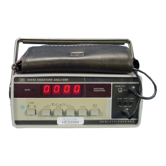
Page REPLACEABLE PARTS 6 . 1 Introduction 6 . 4 Ordering Information 6 . 6 HP Part Number Organization 6 . 8 Component Parts and Materials 6 . 1 1 General Usage Parts 6 . 1 3 Specific Instrument Parts 6 . - Page 6 SELF-TEST and NORMAL/SERVICE Signatures 8-13 Title Page Figure Model 5004A Signature Analyzer Power Cable HP Part Numbers Versus Mains Plugs Available Front Panel. Probe. and Pod Features ........... Operator Self-Test Operating nstructions Typical Connections of 5004A to Device Under Test Probe.
-
Page 7: Safety Considerations
Model Safety Considerations SAFETY CONSIDERATIONS GENERAL This is a Safety Class I instrument. This instrument has been designed and tested according to IEC Publication 348, "Safety Requirements for Electronic Measuring Apparatus." OPERATION BEFORE APPLYING POWER verify that the power transformer primary i s matched to the available line voltage and the correct fuse i s installed (see Section Make sure that only fuses with the required rated current and of the specified type (normal blow, timedelay, etc.) are... - Page 8 Model 5004A Safety Considerations WARNING IF THlS INSTRUMENT IS T O BE ENERGIZED VIA A N AUTOTRANS- FORMER (FOR VOLTAGE REDUCTION) M A K E SURE THE C O M M O N TERMINAL IS CONNECTED T O THE EARTHED POLE O F THE POWER SOURCE.
-
Page 10: Options (Line Voltages)
1-7. Options for the 5004A are the four possible line voltage settings for the instrument. (Any the line voltage setting.) The four option numbers are the same a s the corresponding line volt- ages: 100, 120, 220, and 240, (e.g., Option 120 is for 120 Volt line supply). -
Page 11: Description Of 5004A Signature Analyzer
1-18. Signature analysis is a method of troubleshooting complex electronic logic circuits to the individual component level. To use signature analysis with the 5004A, the unit to be tested must have certain characteristics included with the original design. Typically a logic product... -
Page 12: Recommended Test Equipment
The 5004A requires four signals from the unit being tested: Clock, Start, Data, and Stop. The CLOCK signal synchronizes the two instruments. The exactly repetitive START and STOP signals define a window during which the DATA signal is being re- ceived by the 5004A. -
Page 13: Recommended Test Equipment
The 5004A requires four signals from the unit being tested: Clock, Start, Data, and Stop. The CLOCK signal synchronizes the two instruments. The exactly repetitive START and STOP signals define a window during which the DATA signal is being re- ceived by the 5004A. -
Page 14: Installation
2-10. Line Voltage Label 2-11. The original line voltage setting for each 5004A a s manufactured is printed on a label on the back panel of each 5004A. Check this label and compare the voltage (100,120,220, or 240) with your local line voltage supply. If you do not have the correct line voltage for your 5004A, notify a qualified technician and refer to Section V of this manual. -
Page 15: Operating Environment
2-15. TEMPERATURE. The 5004A may be operated in temperatures from O C to +55OC. 2-16. HUMIDITY. The 5004A may be operated in environments with humidity up to 95%. However, it should be protected from temperature extremes which cause condensation in the instrument. -
Page 16: 2-18. Storage And Shipment
Model 5004A 2-18. STORAGE AND SHIPMENT 2-19. Environment The instrument may be stored or shipped in environments within the following limits: Temperature Humidity Up to 95% .... Altitude 4,600 meters (15,000 feet) 2-21. The instrument should also be protected from temperature extremes which cause con- densation within the instrument. -
Page 17: Operation
11- 11 I 3-7. The characters presented on the display are a hexadecimal number which is the residue of a count in the 5004A after a START and a STOP signal have been received with some data bits in between. - Page 19 LINE OFF ON Switch: (Indicates switch position.) This switch controls application of mains line power to the 5004A. Line power i s applied when the switch is pushed and locked in. Line power i s disconnected when the switch is out. (See SWITCH NOTE.) Handle-Stand: The combination handle and stand can be rotated by pulling gently at the side pivot points both sides simultaneously and turning the handle to the desired position.
-
Page 21: 3-12. Operator's Maintenance
Push the probe tip point gently and firmly into the PROBE TEST receptacle until the point held securely. 4. Connect the 5004A power cable to the correct power source and set the 5004A front panel as follows for the displays shown: .Switch Settings... -
Page 23: Instruments Compatible With 5004A
OPERATING INSTRUCTIONS 3-19. Figure shows operating procedures for the 5004A Signature Analyzer. Refer to the instruction manual of the instrument to be tested for detailed steps for use of the 5004A Signa- ture Analyzer. OPERATING INSTRUCTIONS Before applying power to the SOMA study and learn the information given in Figure Front Panel Features and perform the Operators Self-Test in Figure 3-2. -
Page 26: Performancetests
4-2. The procedures in this section test the instrument's electrical performance using the specifications of Table 1-1 a s the performance standards. All tests can be performed without access to the interior of the 5004A. A simpler operational test is included in Section Ill under Operator's Check. -
Page 27: Positive Pulse Performance Test
POWER SUPPLY KEEP GROUND LEADS SHORT Figure 4-7. Logic Level Performance Test Setup POSITIVE PULSE PERFORMANCE TEST 4-7. With test equipment connected a s in Figure 4-2, proceed a s follows: Set Pulse Generator to output a positive-going 5-volt/lO ns pulse. Set Pulse Generator repetition rate to approximately one-pulse-per-second. -
Page 28: Negative Pulse Performance Test
4-8. NEGATIVE PULSE PERFORMANCE 'TEST 4-9. With test equipment connected a s in Figure 4-3, proceed a s follows: Set pulse generator to output a negative-going pulse. Adjust pulse generator to give waveform at probe tip a s shown in Figure 4-3, with a repetition rate of one-pulse-per-second. -
Page 32: Adjustments
The 5004A top cover must be removed to change the power transformer primary (line voltage change). The data probe covers must be removed to set the threshold. -
Page 35: Replaceable Parts
This section contains information for ordering replacement parts. Table 6-7 lists parts in alphanumerical order of their reference designators and indicates the description and HP Part Number of each part, together with any applicable notes. The table includes the following information. - Page 36 Model 5004A Replaceable Parts ABBREVIATIONS (CONTINUED) electromotive force millihenry TERM negative thin-film transistor processing =minimum toggle ELECT electrolytic =minute (time) peak =thread encapsulated minute (plane angle) THRU through external =miniature phase lock oscillator titanium millimeter phase modulallon tolerance modulator positive-negative-...
-
Page 37: Ordering Information
6-8. Component Parts and Materials 6-9. Generally, the prefix of HP part numbers identifies the type of device. Eight-digit part numbers are used, where the four-digit prefix identifies the type of component, part,or material and the four-digit suffix indicates the specific type. Following i s a list of some of the more com- monly used prefixes for component parts. -
Page 38: 6-11. General Usage Parts
6-14. These are HP manufactured parts for use in individual instruments or series of instru- ments. For these parts, the prefix indicates the instrument and the suffix indicates the type of part. For example, 05004-60003 is an assembly used in the 5004A. Following i s a list of suffixes commonly used. - Page 39 Model 5004A Replaceable Parts Table 6-1. Replaceable Parts HP Part Reference Description Mfr Part Number Designation Number Code I8480 CAPACITOR-CXD 68UC+-10s 6vOC TA CAPACITOR-CXD bIUC+-10s 6vDC TA 0160-I011 CAPACITOR-CXD .OlUC +80-20s LOOVDC CLR I8480 CAPACITOR-CXD .OlUf +#O-ZOS lOOVDC CLR CAPACITOR-CXD .OlUC +80-2OI IOOVDC CLR CAPACITOR-CXD .OlUf +80-I01 lOOVOC CLR...
- Page 40 Model 5004A Replaceable Parts Table 6-1. Replaceable Parts (Continued) HP Part Reference Description Mfr Part Number Designation Number Code 01607 01607 0611- 1011 NETWORM-RE1 6-PIN-(I? SWITCH A~ILMBLYI 5-ITATION 3101.2118 5- ITATION 1101- 1111 28480 18480 1 111-4101 1111- 4101 28480...
- Page 41 Reference HP Part Description Designation Number Code Mfr Part IUumber CONTACT-CONN U/W=CD8T=TVCL MALL DC8LOR CONTACT-CONN U/W-CD8T-TYPE MALE DC8LDR 28480 CONTACT-CONN U/W-CO8T=TVCE MILE DP8LOR CONTACT-CONN U/W-C08T=TVCE MALL DC8LDR CONTACT-COYN U/W-CO8T-TVCE MALL DCILOR CONTACT-CONN U/W-C08T=TYCL MALE DC8LOR CONTACT-CONN UIW-CO8T-TYPE MALE OC8LDR CONTACT-CONN U/W=CO8T=TVCE MALE DC8LDR...
- Page 42 Model 5004A Replaceable Parts Table 6-7. Replaceable Parts (Continued) HP Part Reference Description Mfr Part Number Designation Number Code 1901-0040 28480 1901-0040 1901-0040 1901-0040 1901-0040 1 1 . S W 0717-1100 1 1 .lZSW 11 .18SW 1 1 ,lZSW I TCmO+-100...
-
Page 43: Manufacturers Code List
Table. 6-2. Manufacturers Code List Z I P Mfr. No. MANUFACTURER NAME ADDRESS CODE 01542 HP DIV 01 OPTOELECTRONICS, PAL0 ALTO, CA ALLEN-BRADLEY CO., MILWAUKEE, W I 01607 TEXAS INSTRU INC SEMICOND CMPNT DIV, DALLAS, TX 01698 02037 MOTOROLA SEMICONDUCTOR PRODUCTS, PHOENIX, AZ 02713 GENERAL INSTR CORP SEMIDON PROD GP., HICKSVILL, NY... -
Page 45: Imanual Changes
Model 5004A Manual Changes SECTION VII MANUAL CHANGES 7-1. INTRODUCTION This section normal.1~ contains information for adapting this manual to instruments for which the content does not apply directly. Since this manual does apply directly to instruments having serial numbers listed on the title page, no change information is given here. Refer to INSTRUMENTS COVERED BY MANUAL in Section I for additional important information about serial number coverage. -
Page 46: Safety Considerations
Model 5004A Service SECTION Vlll SERVICE 8-1. INTRODUCTION 8-2. This section provides safety considerations, logic symbols, troubleshooting procedures, block diagram and description, circuit theory, component location photos, and schematic dia- gram (service information). 8-3. SAFETY CONSIDERATIONS 8-4. Although this instrument has been designed in accordance with international safety... -
Page 47: Recommended Test Equipment
Service 8-9. RECOMMENDED TEST EQUIPMENT 8-10. Test equipment and test equipment accessories required to maintain the 5004A are listed in Table 7-2. Equipment other than that listed may be used if it meets the listed critical specifications. 8-11. LOGIC SYMBOLS 8-12. -
Page 48: Logic Implementation And Polarity Indication
Model 5004A Service EXAMPLE 1 says that Z is not true if A is true and B is true or that Z is true if A and B are not both true. Z=AB or Z=AB. This is frequently referred to a s NAND (for NOT AND). - Page 49 M o d e l 5004A Service NEGATIVE LOGIC Alternatively, by assigning the relationship H=O, L=l at both input and output, Device #I can perform the OR function and Device #2 can perform the AND function. Such consistent assignment referred to as negative logic. The corresponding logic symbols would be:...
-
Page 50: Other Symbols
Model 5004A Service 8-25. The choice of symbol may be influenced by these considerations: (1)Theoperation being performed may best be understood as A N D or OR. (2) In a function more complex than a basic gate, the inputs will usually be considered as inherently active high or active low (e.g., the understanding and the writing of logic equations are often facilitated if active-low or negated outputs feed into active-low or negated inputs. -
Page 51: Dependency Notation "C" "G" "V" "F
INPUT. Similar to the S input except if both and K (see below) are at flip-flop changes state. K INPUT. Similar to the R input (see above). D INPUT (Data). Always dependent on another input (usually C). When the the flip-flop will be set. When the C is and the the flip-flop will reset. -
Page 52: Control Blocks
Model 5004A Service 8-30. Control Blocks 8-31. A class of symbols for complex logic are called control blocks. Control blocks are used to show where common control signals are applied to a group of functionally separate units. Examples of types of control blocks follow. -
Page 53: Complex Logic Devices
M o d e l Service 8-32. Complex Logic Devices 8-33. Logic elements can b e combined t o produce very complex devices that can perform more difficult functions. control block symbol can b e used b o simplify understanding of many complex devices. -
Page 54: Troubleshooting (Failure Analysis)
A high output is usually supplied by a resistor to a "high" voltage. 8-34. TROUBLESHOOTING (FAILURE ANALYSIS) 8-35. Information to help locate a fault or trouble in the 5004A i s given in the following material. 8-36. Several troubleshooting aids are permanently built-in the 5004A. The SELF-TEST front panel switch is one. -
Page 56: Troubleshooting Signatures Major Test Points
Model 5004A Service Table 8-1. Troubleshooting Signatures Major Test Points Signature Location N O R M A L SERVICE I I / 1 Figure 8-7. Troubleshooting Flowchart 8-1 1... -
Page 59: Data Probe Disassembly And Reassembly
Data Probe Disassembly and Reassembly 8-47. To disassemble the data probe, use the following procedure. Disconnect the power cable from the 5004A. Remove the GND wire from the probe. Figure 6-7 shows the mechanical parts of the probe. Figure 8-7shows the probe with its covers removed. -
Page 60: Block Diagram Description
UNSTABLE SIGNATURE lamp if two suc- ceeding signatures are different. The R E S E T function for the entire 5004A i s part of the DATA probe. R E S E T is activated by a switch (labeled RESET) on the DATA probe. -
Page 62: Display Scan And Comparator Strobe
8-70. Schematic Diagram 8-71. The 5004A schematic diagram i s presented with the four inputs on the left side, and the flow of signals i s generally from the left to the right side where the output indicators are pre- sented. -
Page 63: Ecl-To-Ttl Level Converters
RUN mode. In the INITIAL state, if START is 0 the state will change to ARMED. In the ARMED state the 5004A is ready to receive a START pulse and proceed to either RUN mode. (Note that if a STOP pulse is received, the state will be intermediate RUN; and to progress to full RUN, STOP must be 0.) From full RUN the state will return to INITIAL if START and STOP... -
Page 64: Pseudo-Random Word Generator (Data Signal Path Continued)
EXPLANATION START SIGNAL (UlA(7)) NO CHANGE STATE STOP SIGNAL (UlB(2)) GATE CONTROL FLIP-FLOPS STATES Figure 8-4. Gate Control State Diagram 8-86. Pseudo-Random Word Generator (Data Signal Path Continued) 8-87. The pseudo-random word generator is the central principle of the signature analysis method. -
Page 65: Display Control (Data Signal Path Continued)
All possible states of the gate control circuit are exercised in each self-test cycle to check proper operation. Self-test signals are applied to the inputs of the 5004A to allow all circuits to be tested. Part of the test besides specific signatures i s to apply trash to U17 which will exercise all seven segments of each display digit. -
Page 66: Schematic Diagram Notes
SCHEMATIC DIAGRAM NOTES Resistance in ohms, capacitance in picofarads, inductance in millihenries unless other- wise noted. Asterisk denotes a factory-selected value. Value shown in typical. Part may be omitted. Tool-aided adjustment. Manual control. Encloses front-panel caption. r - - - 1 Encloses rear-panel caption.