Philips МСМ1006 Service Manual
Hide thumbs
Also See for МСМ1006:
- Service manual (24 pages) ,
- User manual (21 pages) ,
- Quick start manual (2 pages)
Advertisement
Quick Links
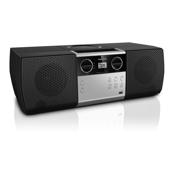
Micro Hi-Fi System
CONTENTS
Technical specification and version variation .........................1-1..1-2
Service measurement setup..........................................................1-3
Service aids .................................................................................1-4
Instructions on CD playability ...............................................2-1.. 2-2
Block diagram................................................................................3-1
Wiring diagram ..............................................................................4-1
Circuit diagram...................................................................... .5-1..5-5
Layout diagram.......................................................................6-1..6-4
Exploded view diagram .................................................................7-1
©
Copyright 2012 Philips Consumer Electronics B.V. Eindhoven, The Netherlands
All rights reserved. No part of this publication may be reproduced, stored in a retrieval
system or transmitted, in any form or by any means, electronic, mechanical, photocopying,
or otherwise without the prior permission of Philips.
Published by GD 1201 Service Audio
Version 1.3
All manuals and user guides at all-guides.com
Subject to modification
.
MCM1006
/51/55/93/77
3141 785 37183
Advertisement

Related Manuals for Philips МСМ1006


Summary of Contents for Philips МСМ1006
-
Page 1: Table Of Contents
Exploded view diagram ..............7-1 © Copyright 2012 Philips Consumer Electronics B.V. Eindhoven, The Netherlands All rights reserved. No part of this publication may be reproduced, stored in a retrieval system or transmitted, in any form or by any means, electronic, mechanical, photocopying, or otherwise without the prior permission of Philips. - Page 2 All manuals and user guides at all-guides.com PCBs location Display board Main board USB BOARD VERSION VARIATION Type /Versions: MCM1006 /51/55/93/77 Service policy Board in used: LATAM/APMEA USB BOARD DISPLAY BOARD MAIN BOARD Type /Versions: MCM1006 Features Feature diffrence /51/55/93 VOLTAGE SELECTOR ECO STANDBY - DARK * TIPS : C -- Component Lever Repair.
- Page 3 All manuals and user guides at all-guides.com DEPICTION Description Page TOP CABINET TUNING KNOB POWER KNOB CD DOOR FUNCTION PUSH KNOB MP3 JACK KNOB VOLUME USB JACK CD FUNCTION CONTROL KNOB 10 FRONT CABINET FUNCTION KNOB 12 DISPLAY LENS SPEAKER NET Battery location CABINET Dimensions with Boxes 532 x 242 x 200mm (LxWxH)
- Page 4 All manuals and user guides at all-guides.com GENERAL DESCRIPTION CDSM with Tuner , CD, USB Aux In, Headphone LIFETIME : 5 Years Class Tuner Supply + Amplifier Loudspeaker Boxes Recorder SAFETY requirements Refer to the section of Version Overview RADIATION / IMMUNITY requirments ( EMC ) Refer to the section of Version Overview CLIMATIC requirements ALL climates...
- Page 5 All manuals and user guides at all-guides.com TECHNIAL DESCRIPTION 2 x 2W matching LOUDSPEAKER of 2 x 4R. One INPUT SOURCE GENERAL PART OUTPUT stage Protection : Yes Temperature : YES Shorcircuit : Yes INDICATORS Standby Mode Indicator : LCD display off ECO Mode Indiicator : NA ELECTRICAL DATA...
- Page 6 Channel Separation(1K) 40dB (Lim. 26dB) Channel Separation(10K) 30dB (Lim. 16dB) CD Shock sens. USB PART - Refer to Philips USB direct user requirement spec. DBB effect 8+/- 2 dB at AUX 500mV, 1kHz CLOCK / CD SPECICFICATION Class No Issued Date...
- Page 7 All manuals and user guides at all-guides.com TECHNIAL DESCRIPTION GENERAL PART WAVE RANGE Refer to version overview Refer to version overview Refer to version overview AERIAL Telescope AM/MW : Ferrite INDICATORS : ELECTRICAL DATA Limit Unit F.M. Limit Unit 10.7 ±...
- Page 8 All manuals and user guides at all-guides.com MEASUREMENT SETUP Tuner FM Bandpass LF Voltmeter 250Hz-15kHz e.g. PM2534 e.g. 7122 707 48001 RF Generator e.g. PM5326 S/N and distortion meter e.g. Sound Technology ST1700B Use a bandpass filter to eliminate hum (50Hz, 100Hz) and disturbance from the pilottone (19kHz, 38kHz). Tuner AM (MW,LW) Bandpass LF Voltmeter...
-
Page 9: Service Aids
All manuals and user guides at all-guides.com SERVICE AIDS WARNING All ICs and many other semi-conductors are susceptible to electrostatic discharges (ESD). Careless handling during repair can reduce life drastically. When repairing, make sure that you are connected with the same potential as the mass of the set via a wrist wrap with resistance. -
Page 10: Instructions On Cd Playability
All manuals and user guides at all-guides.com 2 - 1 INSTRUCTIONS ON CD PLAYABILITY Customer complaint "CD related problem" Set remains closed! check playability playability ok ? For flap loaders (= access to CD drive possible) "fast" lens cleaning cleaning method is recommended check playability playability... - Page 11 All manuals and user guides at all-guides.com 2 - 2 INSTRUCTIONS ON CD PLAYABILITY PLAYABILITY CHECK LIQUID LENS CLEANING Before touching the lens it is advised to clean the surface of the lens by blowing clean air over it. For sets which are compatible with CD-RW discs This to avoid that little particles make scratches on use CD-RW Printed Audio Disc ....7104 099 96611 the lens.
-
Page 12: Block Diagram
All manuals and user guides at all-guides.com 3 - 1 3 - 1 BLOCK DIAGRAM... -
Page 13: Wiring Diagram
All manuals and user guides at all-guides.com 4 - 1 4 - 1 WIRING DIAGRAM... - Page 14 All manuals and user guides at all-guides.com 5 - 1 5 - 1 CIRCUIT DIAGRAM-MAIN BOARD PART 1 SEV_3V3 3V3SD_IC 3V3SD FELPFO CN926 CN926 TELPFO C934 C934 0.1uF/0603 0.1uF/0603 3V3SD C901 C901 0.1uF/0603 0.1uF/0603 DGND SBLPFO AGND DGND R999 R999 D903 D903 DATA...
- Page 15 All manuals and user guides at all-guides.com 5 - 2 5 - 2 CIRCUIT DIAGRAM-MAIN BOARD PART 2 3V3SD L901 L901 300R/100MHz 300R/100MHz +5VCC VREF_16 +5VCC C917 0.01UF C917 0.01UF VREF_16 R923 R923 TRACK C36 Cap 0.1U connect VCC2 XTRACK EC914 EC914 C919...
- Page 16 All manuals and user guides at all-guides.com 5 - 3 5 - 3 CIRCUIT DIAGRAM-MAIN BOARD PART 3 3V3SD BC902 BC902 IC904 IC904 0.1U 0.1U DGND DQ15 DQ14 GNDQ GNDQ DQ13 DQ12 VCCQ VCCQ DQ11 DQ10 GNDQ GNDQ VCCQ VCCQ RDQML RDQML LDQM...
- Page 17 All manuals and user guides at all-guides.com 5 - 4 5 - 4 CIRCUIT DIAGRAM-MAIN BOARD PART 4 DISCONNECT POWER CORD BEFORE SERVING RADIO SIGNAL RECOMMEND THE UNIT BE OPERATED BY DC 12V VOLTS DURING TROUBLE SHOOTING CD SIGNAL COMPONENTS MARKED WITH HAVE CRITICAL AUX SIGNAL CHARACTERISTICS.ONLY REPLACE WITH THE COMPONENT OF THE SAME...
-
Page 18: Circuit Diagram
All manuals and user guides at all-guides.com 5 - 5 5 - 5 CIRCUIT DIAGRAM-DISPLAY BOARD/TUNER BOARD CN701 CN701 AUX_RCH R389 R389 L304 L304 $$$6310 AUX_LCH L305 L305 R386 R386 $$$9721 $$$6309 L701 L701 $$$14886 2K5/100MHz 2K5/100MHz $$$9723 R701 R701 JK302 JK302 100R... -
Page 19: Layout Diagram
All manuals and user guides at all-guides.com 6 - 1 6 - 1 LAYOUT DIAGRAM-MAIN BOARD TOP SIDE VIEW... - Page 20 All manuals and user guides at all-guides.com 6 - 2 6 - 2 LAYOUT DIAGRAM-MAIN BOARD BOTTOM SIDE VIEW...
- Page 21 All manuals and user guides at all-guides.com 6 - 3 6 - 3 LAYOUT DIAGRAM-TUNER & DISPLAY BOARD TOP SIDE VIEW BOTTOM SIDE VIEW...
- Page 22 All manuals and user guides at all-guides.com 6 -4 6 - 4 LAYOUT DIAGRAM-USB BOARD TOP SIDE VIEW BOTTOM SIDE VIEW...
- Page 23 All manuals and user guides at all-guides.com 7 -1 7 - 1 EXPLODED VIEW...
- Page 24 All manuals and user guides at all-guides.com Revision List Revision List Version 1.0 * Initial Release Version 1.1 * Add /93 version Version 1.2 * Add /51 version Version 1.3 * Add /77 version on wk1218 14-1...