Table of Contents
Advertisement
Quick Links
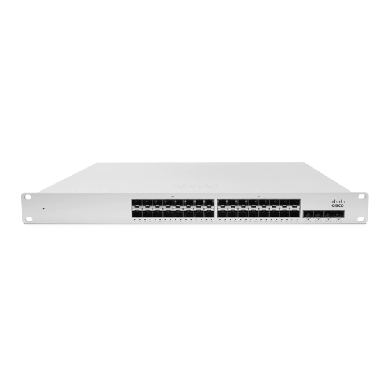
MS410 Series Installation Guide
About this Guide
This guide provides instruction on how to install and configure your MS410 series switch. This guide also provides
mounting instructions and limited troubleshooting procedures. For more switch installation guides, refer to
the
switch installation guides section
Product Overview
Models
Model number
MS410-16
MS410-32
Physical Specifications
1GbE SFP
10GbE SFP+ uplink
40G QSFP+ Stacking ports
Dedicated Mgmt Interface
Hot Swap Power Supply
on our documentation website.
Description
Layer-3 16-port 1Gbe SFP and 2-port
10Gbe SFP+ aggregation switch with 1
management interface and hot-swappable power
supplies / fans
Layer-3 32-port 1Gbe SFP and 4-port 10Gbe
SFP+ aggregation switch with 1 management
interface and hot-swappable power supplies / fans
MS410-16
16
2
2
1
Yes, Dual
MS410-32
32
4
2
1
Yes, Dual
1
Advertisement
Table of Contents

Related Manuals for Cisco Meraki MS410 Series


Summary of Contents for Cisco Meraki MS410 Series
- Page 1 MS410 Series Installation Guide About this Guide This guide provides instruction on how to install and configure your MS410 series switch. This guide also provides mounting instructions and limited troubleshooting procedures. For more switch installation guides, refer to switch installation guides section on our documentation website.
- Page 2 Hot Swap Fans Yes, 2x Yes, 2x Power Input 100 - 240 VAC, 47-63 Hz 100 - 240 VAC, 47-63 Hz 50-85W 50-85W Power Consumption 32°F - 104 °F 32°F - 104 °F Operating Temperature 0°C - 40 °C 0°C - 40 °C -4°F - 158°F -4°F - 158°F Storage and Transportation Temperature...
-
Page 3: Ports And Status Indicators
• Press and hold for more than 10 sec: To force the unit into a full factory restore. Ports and Status Indicators The MS uses LEDs to inform the user of the device's status. When the device powers on, the main LED will be amber. Additional functions are described below, from left to right. -
Page 4: Factory Reset Button
Switch Port LEDs No client connected 1 Gbps on SFP+ Solid orange 1 Gbps on SFP/10 Solid green Gbps on SFP+ Factory Reset Button If the button is pressed and held for at least 10 seconds and then released, the switch will reboot and be restored to its original factory settings by deleting all configuration information stored on the unit. -
Page 5: Package Contents
Package contents In addition to the MS switch, the following are provided (mounting kit provided with 1U models only): Rack Mount Kit includes: ▪ US 12-24 mounting screws and cage nuts, 5 of each ▪ INTL M5 mounting screws and cage nuts, 5 of each ▪... -
Page 6: Pre-Install Preparation
Pre-install Preparation You should complete the following steps before going on-site to perform an installation. Configure your Dashboard Network The following is a brief overview only of the steps required to add a switch to your network. For detailed instructions about creating, configuring and managing Meraki networks, refer to the online documentation (documentation.meraki.com). -
Page 7: Assigning An Ip Address
current list of outbound ports and IP addresses for your particular organization can be found on the firewall configuration page in your dashboard. Assigning an IP Address All switches must be assigned routable IP addresses. These IP addresses can be dynamically assigned via DHCP or statically assigned. -
Page 8: Installation Instructions
static IP addresses on the upstream DHCP server. Through “DHCP reservations,” IP addresses are “reserved” for the MAC addresses of the Meraki switches. Please consult the documentation for the DHCP server to configure DHCP reservations. Installation Instructions Note: Each switch comes with a graphical instruction pamphlet within the box. This pamphlet contains detailed step by step guides and images to assist in the physical install of the switch. - Page 9 3. Insert the power supply unit into the back of the switch. After it has been securely installed, you can connect power to the power supply unit.
-
Page 10: Mounting Hardware
Mounting hardware The mounting hardware includes integrated mounting ears for standard 1U racks. When installing the device, make sure that there is sufficient space between the rear of the rack and other obstacles to ensure adequate airflow. Bringing your Stack Online The steps below explain how to prepare a group of switches for physical stacking, how to stack them together, and how to configure the stack in Dashboard. - Page 11 2. Connect each switch with individual uplinks to bring them both online and ensure they can check in with the Meraki Dashboard. 3. Download the latest firmware build using the Firmware Upgrade Manager under Organization > Monitor > Firmware Upgrades, if they are not already set for this. This helps ensure each switch is running the same firmware build.
-
Page 12: Warranty
If you are still experiencing hardware issues, please contact Cisco Meraki support by logging in to dashboard and using the Help option near the top of the page, then opening and email case or calling using the contact information on that page. - Page 13 Meraki data sheets. If your Cisco Meraki device fails and the problem cannot be resolved by troubleshooting, contact support to address the issue. Once support determines that the device is in a failed state, they can process an RMA and send out a replacement device free of charge.
- Page 14 • Rules and conditions for the sale of equipment are determined by the terms of contracts concluded by Cisco or authorized Cisco partners with equipment buyers. • Disposal of a technical device at the end of its service life should be carried out in accordance with the requirements of all state regulations and laws.