Table of Contents
Advertisement
Quick Links
I n s t a l l a t i on a n d St a r t -Up I n s t r u ct i on s
Reg i s t er 3
RX B7-120 .0 33.0 1.10 .0 2
Repl a ces : RX B7-120 .0 33.0 1.0 9.0 2
W ei t er g a be sow i e Vervi el f ä l t i g u n g di eser U n t erl a g e, Ver w er t u n g u n d
M i t t ei l u n g i hres I n ha l t s n i cht g es t a t t et , s ow ei t n i cht a u s dr ü ck l i ch zu g e-
s t a n den . Zu w i der ha n dl u n g ver pf l i cht en zu Scha den er s a t z. A l l e
Recht e f ü r den Fa l l der Pa t en t ertei l u n g oder G M -Ei n t r a g u n g vorbeha l t en .
Propr i et r y da t a , com pa n y con f i den t i a l . A l l r i g ht s reser ved.
Con f i é a t i t r e de s ecr et d'en t er pr i se. Tou s droi t s r éservés .
Con f i a do com o s ecr et o i n du s t r i a l . Nos reser va m os t odos l os der echos .
en g l i s h
0 5.98
Advertisement
Table of Contents

Related Manuals for Siemens MAMMOMAT 300


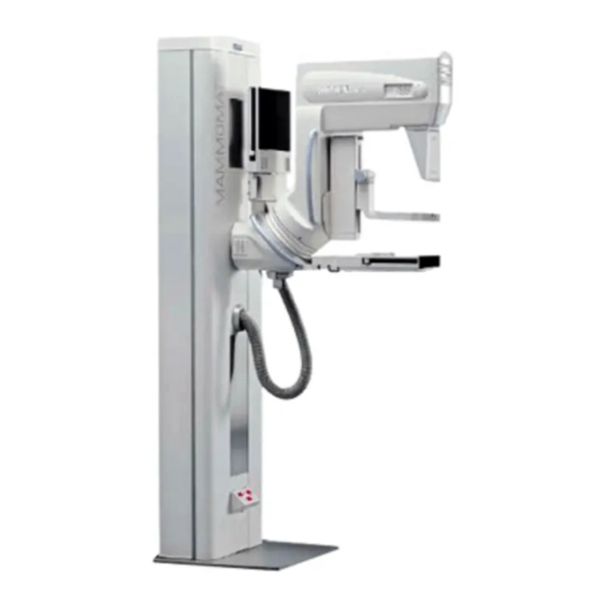
Summary of Contents for Siemens MAMMOMAT 300
- Page 1 I n s t a l l a t i on a n d St a r t -Up I n s t r u ct i on s Reg i s t er 3 RX B7-120 .0 33.0 1.10 .0 2 en g l i s h 0 5.98 Repl a ces : RX B7-120 .0 33.0 1.0 9.0 2...
-
Page 2: Table Of Contents
EMC measures on the bottom plate Fitting the cables X1, X8 and X9 on the bottom plate Connecting the stand cable-harness The high-voltage connectors, alternative types Connecting the high-voltage connector Siemens-Elema AB SPS-UD RX B7-120.033.01.10.02 MAMMOMAT 300 Solna, Sweden 05.98 65 02 186... - Page 3 Oscilloscope diagrams 11-3 12 Start-up and functional test of the IONTOMAT 12-1 Checking and programming with the service PC 12-1 Sensitivity 12-1 Sensitivity correction 12-2 Correction curve 12-2 Siemens-Elema AB SPS-UD RX B7-120.033.01.10.02 MAMMOMAT 300 Solna, Sweden 05.98 65 02 186...
- Page 4 17 Checking the exposure blocking 17-1 Checking the exposure blocking 17-1 18 Checking the radiation field limitation 18-1 Checking the radiation field limitation 18-1 General 18-1 Measuring procedure 18-1 Evaluation 18-2 Siemens-Elema AB SPS-UD RX B7-120.033.01.10.02 MAMMOMAT 300 Solna, Sweden 05.98 65 02 186...
- Page 5 20-1 21 Appendix 21-1 Working with the service PC 21-1 Description of the syntax used in these instructions 21-1 Connecting the service PC 21-2 Measuring protocol 21-3 Siemens-Elema AB SPS-UD RX B7-120.033.01.10.02 MAMMOMAT 300 Solna, Sweden 05.98 65 02 186...
-
Page 6: Prerequisites
• Densitometer e.g PDA 81. • Service PC (e.g Siemens-Nixdorf PCD 3NSX/20 or similar) with connecting cable (PC-Generator), part no. 96 00 440 RE999. • Normi 7 test body (provided by the customer) or SIB phantom Type 42 001 (PTW or INAK). -
Page 7: Start-Up, Dhhs And X-Ray Decree Area Of Application
Start-up, DHHS and X-ray decree area of application Important notes on start-up The MAMMOMAT 300 is adjusted, programmed and tested in the factory, leaving only the adaption to the on-site mains voltage and the functional tests to be performed. When the measurements to be made (kV, mAs, etc.) are within the tolerances stated in these instructions, this confirms that the settings made in the factory have not changed and the equipment is fully serviceable. -
Page 8: Checking And Recording For The Dhhs Area Of Application
Note on delivery state The MAMMOMAT 300 has been tested and adjusted at the factory, and should therefore be ready for operation after completion of the installation. Siemens-Elema AB SPS-UD RX B7-120.033.01.10.02... - Page 9 Prerequisites This page intentionally left blank. Siemens-Elema AB SPS-UD RX B7-120.033.01.10.02 MAMMOMAT 300 Solna, Sweden 05.98 65 02 186...
-
Page 10: Protective Measures
(ground before making contact and place only on a conductive sur- face, see Technical Information TI 219). Before removing or inserting a p.c. board, switch off the equipment. Siemens-Elema AB SPS-UD RX B7-120.033.01.10.02 MAMMOMAT 300 Solna, Sweden 05.98 65 02 186... - Page 11 Protective measures This page intentionally left blank. Siemens-Elema AB SPS-UD RX B7-120.033.01.10.02 MAMMOMAT 300 Solna, Sweden 05.98 65 02 186...
-
Page 12: Preparatory Work
Preparatory work General Scope of delivery The MAMMOMAT 300 is packed in one crate and one cardboard box: Crate (length 2140 mm, width 800 mm, height 1375 mm) The crate contains: • Compression plate. packed together in a separate box •... -
Page 13: Unpacking The Stand
Remove the remaining walls (3). Upend the stand (4) , with pallet (5) (two persons are required). Loosen the four bolts (6) and remove the pallet (5). Siemens-Elema AB SPS-UD RX B7-120.033.01.10.02 MAMMOMAT 300 Solna, Sweden 05.98 65 02 186... -
Page 14: Removing The Transport Safeguards
Removal of the swivel-arm system transport safeguard is done after the equipment has been powered up, see further section "Attaching the swivel-arm covers", page 8-1. Transport safeguard for the lifting carriage Figure 3 Transport safeguard for the lifting carriage Siemens-Elema AB SPS-UD RX B7-120.033.01.10.02 MAMMOMAT 300 Solna, Sweden 05.98 65 02 186... -
Page 15: Transport Safeguard For The Rotary Motion
The edges of the metal curtain are very sharp and are therefore provided with protective strips (1) on delivery. These strips must always be applied onto the edges of the metal cur- tain during service and maintenance work. Siemens-Elema AB SPS-UD RX B7-120.033.01.10.02 MAMMOMAT 300 Solna, Sweden 05.98 65 02 186... -
Page 16: Unpacking The Generator And Mounting The Radiation Field
Upend the generator (1) and lift it off the pallet (2) (two persons are required). Mount one stanchion (3) for the lead-glass pane (4) onto the generator. Siemens-Elema AB SPS-UD RX B7-120.033.01.10.02 MAMMOMAT 300 Solna, Sweden 05.98 65 02 186... - Page 17 Fit the lead-glass pane (4) into the groove of the stanchion and keep it in position while mounting the other stanchion onto the generator. Cover the holes with plastic caps (7). Siemens-Elema AB SPS-UD RX B7-120.033.01.10.02 MAMMOMAT 300 Solna, Sweden 05.98 65 02 186...
-
Page 18: Installing The Generator And The Stand
(shorter distances may be used at the customer´s desire, if in compliance with lo- cal regulations). For the installation of the cable duct, a minimum distance of 150 mm between wall and stands is required. Siemens-Elema AB SPS-UD RX B7-120.033.01.10.02 MAMMOMAT 300 Solna, Sweden 05.98 65 02 186... -
Page 19: Removing The Generator Cover
They are needed again when reassembling the front cover to establish protective ground connection and to fulfil EMC (Electro Magnetic Compatibility) requirements. Remove the front cover (3) from the generator. Figure 2 Removing the generator cover Siemens-Elema AB SPS-UD RX B7-120.033.01.10.02 MAMMOMAT 300 Solna, Sweden 05.98 65 02 186... -
Page 20: Installing The Cable Ducts
Fasten the bottom plate of the cable ducts (6) to the floor according to marking, using double-sided adhesive tape. Cover the cable entry at the generator that is not used with the enclosed cover plate (7). Siemens-Elema AB SPS-UD RX B7-120.033.01.10.02 MAMMOMAT 300 Solna, Sweden 05.98 65 02 186... -
Page 21: Laying The Cable Harness
High voltage cable H1. IONTOMAT signal cable X11. Unit control cable X1. Power supply cable X14. Anode rotation cable X9. Filament cable X8. Mains supply cables: Protective ground. Siemens-Elema AB SPS-UD RX B7-120.033.01.10.02 MAMMOMAT 300 Solna, Sweden 05.98 65 02 186... -
Page 22: Aligning The Stand
Cover the levelling screws with the cover discs supplied. Figure 5 Levelling screws NOTE! If bolting to the floor is required, please refer to section 20 page 1. Siemens-Elema AB SPS-UD RX B7-120.033.01.10.02 MAMMOMAT 300 Solna, Sweden 05.98 65 02 186... - Page 23 Installing the generator and the stand This page intentionally left blank. Siemens-Elema AB SPS-UD RX B7-120.033.01.10.02 MAMMOMAT 300 Solna, Sweden 05.98 65 02 186...
-
Page 24: Cable Connections
Hose clamps are included in the delivery. Fold the shield braid (1) backwards over the U-bracket (2) on each cable and clamp with a hose clamp (3). Siemens-Elema AB SPS-UD RX B7-120.033.01.10.02 MAMMOMAT 300 Solna, Sweden 05.98 65 02 186... - Page 25 Provide each incoming cable with a ferrite sleeve (4) except for mains supply cables L1 and L2 and the ground wire which shall be laid together in one and same ferrite sleeve. Ferrite sleeves are included in the delivery. Siemens-Elema AB SPS-UD RX B7-120.033.01.10.02 MAMMOMAT 300 Solna, Sweden 05.98 65 02 186...
-
Page 26: Emc Measures On The Bottom Plate
Install and tighten the four screws (3) and contact washers (4) at the bottom plate. NOTE! Cable X9 shall be clamped to the side wall of the cabinets, if this is not already done see Figure 7 in this section. Siemens-Elema AB SPS-UD RX B7-120.033.01.10.02 MAMMOMAT 300 Solna, Sweden 05.98 65 02 186... -
Page 27: Connecting The Stand Cable-Harness
Make sure that there aren’t any air bubbles between the disc and the connector. Siemens-Elema AB SPS-UD RX B7-120.033.01.10.02 MAMMOMAT 300 Solna, Sweden 05.98 65 02 186... -
Page 28: Connecting The High-Voltage Connector
Plug in the high-voltage connector (1) at H1. Tighten the sleeve nut (2) by hand. Position the high-voltage cable (3) to the right in the generator and fasten with cable ties (4). Siemens-Elema AB SPS-UD RX B7-120.033.01.10.02 MAMMOMAT 300 Solna, Sweden 05.98 65 02 186... -
Page 29: Connecting The Cable Harness To The Generator
Connect the power supply cable X14 to D711 X14 (3). Strain relieve it on the side with a cable tie (4). IONTOMAT signal cable X11 Connect the IONTOMAT signal cable connector X11, to D700 X11 (5). Siemens-Elema AB SPS-UD RX B7-120.033.01.10.02 MAMMOMAT 300 Solna, Sweden 05.98 65 02 186... - Page 30 Fit the cable to the chassis by using a cable clamp (3). CAUTION! When fitting the cable clamp, ensure satisfactory contact between shield braid (4) and chassis. Siemens-Elema AB SPS-UD RX B7-120.033.01.10.02 MAMMOMAT 300 Solna, Sweden 05.98 65 02 186...
-
Page 31: Mains Connection
Connect the incoming mains cable (1) to X899 (2) in the stand as shown in Figure 8 and Figure 9. Fit plastic tubes (4) on the plates. Strain-relieve (3) the incoming mains cable. Siemens-Elema AB SPS-UD RX B7-120.033.01.10.02 MAMMOMAT 300 Solna, Sweden 05.98 65 02 186... -
Page 32: Connecting The Mains Supply To The Generator
Connect the mains supply cables between stand and generator to fuses F10 and F20 on the generator. Wire marked L1 to F10 and L2/N to F20. Connect the protective ground wire from the stand to the generator (3). Siemens-Elema AB SPS-UD RX B7-120.033.01.10.02 MAMMOMAT 300 Solna, Sweden 05.98 65 02 186... -
Page 33: Measures For Changing From 2-Phase To 1-Phase Connection
(0V) is connected to terminal N and fuse F20. NOTE! Connections on transformer T10 must be adjusted according to actual voltage, for details see Wiring Diagram. Siemens-Elema AB SPS-UD RX B7-120.033.01.10.02 MAMMOMAT 300 Solna, Sweden 05.98 65 02 186... -
Page 34: Modifying The Object Tables
Mount the carbon fibre-plate (1) and pay attention to the brass grounding strap (9). NOTE! Before mounting the carbon-fibre plate, make sure that the grid is properly positioned on the support (10). Siemens-Elema AB SPS-UD RX B7-120.033.01.10.02 MAMMOMAT 300 Solna, Sweden 05.98 65 02 186... - Page 35 Mount the carbon-fibre plate (1) and pay attention to the brass grounding strap (10). NOTE! Before mounting the carbon-fibre plate, make sure that the grid (11) is properly posi- tioned on the support. Siemens-Elema AB SPS-UD RX B7-120.033.01.10.02 MAMMOMAT 300 Solna, Sweden 05.98 65 02 186...
-
Page 36: Mains Connection And Power Supply
Remove fuses F10 (1) and F20 (2) or, when single-phase supply, fuse F10 (1). Connect line resistance meter to fuse holders F10 and F20. Mains supply "ON". Carry out measurement. Mains supply "OFF". Siemens-Elema AB SPS-UD RX B7-120.033.01.10.02 MAMMOMAT 300 Solna, Sweden 05.98 65 02 186... -
Page 37: Checking The Line Voltage In The Generator
Check that the mains voltage agrees with the voltage plugged on transformer T10 (3) and p.c. board D711 (4), located above line filter Z1 (5). Mains supply "OFF". Reinsert fuses F10 (1) and F20 (2). Siemens-Elema AB SPS-UD RX B7-120.033.01.10.02 MAMMOMAT 300 Solna, Sweden 05.98 65 02 186... -
Page 38: Checking The Supply Voltages
Check that the following orange diodes are "ON" on p.c. board D704: • V39 (+15 V) • V38 (-15 V) • V41 (+5 V) • V40 (+24 V) Siemens-Elema AB SPS-UD RX B7-120.033.01.10.02 MAMMOMAT 300 Solna, Sweden 05.98 65 02 186... - Page 39 Mains connection and power supply This page intentionally left blank. Siemens-Elema AB SPS-UD RX B7-120.033.01.10.02 MAMMOMAT 300 Solna, Sweden 05.98 65 02 186...
-
Page 40: Attaching The Swivel-Arm Covers
Figure 1 Connecting the cables Before installing side covers, cables are to be connected. Connect cables X807 (1) to control-button circuit boards D807 (2). Connect ground wires to patient handles (3). Siemens-Elema AB SPS-UD RX B7-120.033.01.10.02 MAMMOMAT 300 Solna, Sweden 05.98 65 02 186... -
Page 41: Attaching The Covers
Don’t forget to fit the sign (3) when mounting the side covers. Use the two longer screws. Mount the front cover (4) over the side covers by engaging the bottom end first, and fasten with two short screws (5). Siemens-Elema AB SPS-UD RX B7-120.033.01.10.02 MAMMOMAT 300 Solna, Sweden 05.98 65 02 186... -
Page 42: Checking The Microprocessors
(2-3 Hz). P.C. board D711: • V9 "ON" (line voltage on). • V13 "OFF" (system stand-by). • V11 "ON" (system on). • V16 "ON" (intermediate circuit - filament). Siemens-Elema AB SPS-UD RX B7-120.033.01.10.02 MAMMOMAT 300 Solna, Sweden 05.98 65 02 186... - Page 43 Checking the microprocessors This page intentionally left blank. Siemens-Elema AB SPS-UD RX B7-120.033.01.10.02 MAMMOMAT 300 Solna, Sweden 05.98 65 02 186...
-
Page 44: Checks Without High Voltage
Release the exposure buttons. NOTE! If the exposure buttons are prematurely released, "Limit" will be indicated. System "OFF". Siemens-Elema AB SPS-UD RX B7-120.033.01.10.02 MAMMOMAT 300 Solna, Sweden 05.98 65 02 186... - Page 45 10-2 Checks without high voltage This page intentionally left blank. Siemens-Elema AB SPS-UD RX B7-120.033.01.10.02 MAMMOMAT 300 Solna, Sweden 05.98 65 02 186...
-
Page 46: Checks With High Voltage
Set the switch S2 (SS) to "ON" (upper position) on p.c. board D702. Remove the jumper and connect the mAs meter to mAs measuring sockets X3 and X4 on p.c. board D710. Siemens-Elema AB SPS-UD RX B7-120.033.01.10.02 MAMMOMAT 300 Solna, Sweden 05.98 65 02 186... -
Page 47: Tube Current Reduction
Tube current reduction NOTE! In MAMMOMAT 300, the tube current reduction is factory set to "ON" (see section 13 and test certificate). In this way, the tube current is reduced to approximately 50 mA at the start of the exposure during the time programmed in section 13. -
Page 48: Oscilloscope Diagrams
Oscilloscope diagrams • MAMMOMAT 300 in mAs mode, see Figure 2-Figure 5. • MAMMOMAT 300 with tube current reduction switched on, Iontomat mode with Bucky, see Figure 6. • MAMMOMAT 300 in Iontomat mode with tube current reduction switched off, see Figure 7. - Page 49 25 kV 100 mAs(P = 3.75 kW) Figure 4 25 kV 1 V/T (1 V= 5 kV) 150 mA 2 V/T (1 V = 80 mA) 0.1 sec/T Siemens-Elema AB SPS-UD RX B7-120.033.01.10.02 MAMMOMAT 300 Solna, Sweden 05.98 65 02 186...
- Page 50 0.5 V/T (1 V = 20 mA) 100 ms/T NOTE! Small focus is selected by attaching a magnification table. NOTE! Record the measured kV and mAs value in the measuring protocol page 21-3. Siemens-Elema AB SPS-UD RX B7-120.033.01.10.02 MAMMOMAT 300 Solna, Sweden 05.98 65 02 186...
- Page 51 30 kV 1 V/T (1 V = 5 kV) 125 mA 1 V/T (1 V = 40 mA) 100 ms/T (total exposure time depending on programmed sensitivity.) Siemens-Elema AB SPS-UD RX B7-120.033.01.10.02 MAMMOMAT 300 Solna, Sweden 05.98 65 02 186...
-
Page 52: Start-Up And Functional Test Of The Iontomat
Indicates the sensitivity for the IONTOMAT channel for contact exposure tables (H) and magnification tables (D). Values from 0 to 31 can be entered. Channel A is not used, the sensitivity is therefore set 0. Siemens-Elema AB SPS-UD RX B7-120.033.01.10.02 MAMMOMAT 300 Solna, Sweden 05.98 65 02 186... -
Page 53: Sensitivity Correction
Press space to change the correction-curve table. 1 Help 2 Save 10 Quit Indicates which correction curve shall be used for contact exposure tables and magnification tables (D). Values shown as delivered. Siemens-Elema AB SPS-UD RX B7-120.033.01.10.02 MAMMOMAT 300 Solna, Sweden 05.98 65 02 186... -
Page 54: Other Film/Screen Combinations
When necessary, curve A2, B2, C2 and D2 can be used for magnification tables and/or A1, B1, C1 and D1 for grid tables. In general, the X1-curves (magnification) correct more than the X2-curves. Siemens-Elema AB SPS-UD RX B7-120.033.01.10.02 MAMMOMAT 300 Solna, Sweden 05.98 65 02 186... -
Page 55: Correction Curve Diagrams
"Quotient" and "Transparency correction" are the values shown in "Normal mode, Ion- tomat data" with the service program. 25 kV Grid thin object quotient thick object Diagram 1 25 kV Magnification thin object quotient thick object Diagram 2 Siemens-Elema AB SPS-UD RX B7-120.033.01.10.02 MAMMOMAT 300 Solna, Sweden 05.98 65 02 186... - Page 56 Start-up and functional test of the IONTOMAT 12-5 27 kV Grid thin object quotient thick object Diagram 3 27 kV Magnification thin object quotient thick object Diagram 4 Siemens-Elema AB SPS-UD RX B7-120.033.01.10.02 MAMMOMAT 300 Solna, Sweden 05.98 65 02 186...
- Page 57 Start-up and functional test of the IONTOMAT 30 kV Grid thin object quotient thick object Diagram 5 30 kV Magnification thin object quotient thick object Diagram 6 Siemens-Elema AB SPS-UD RX B7-120.033.01.10.02 MAMMOMAT 300 Solna, Sweden 05.98 65 02 186...
- Page 58 Start-up and functional test of the IONTOMAT 12-7 35 kV Grid thin object quotient thick object Diagram 7 35 kV Magnification thin object quotient thick object Diagram 8 Siemens-Elema AB SPS-UD RX B7-120.033.01.10.02 MAMMOMAT 300 Solna, Sweden 05.98 65 02 186...
-
Page 59: Checking The Film Density
Change to magnification table, if used, and program "Sensitivity D" for the density as above. The final values are dependent on the type of cassette used and desired optical density. Siemens-Elema AB SPS-UD RX B7-120.033.01.10.02 MAMMOMAT 300 Solna, Sweden 05.98 65 02 186... -
Page 60: Checking The Automatic Transparency Adaption
These limits apply for film with max. gamma 4.0 measured at the density chosen. NOTE! The film density levels may vary from cassette to cassette. Therefore, be sure to use the same cassette for all test exposures. Siemens-Elema AB SPS-UD RX B7-120.033.01.10.02 MAMMOMAT 300 Solna, Sweden 05.98 65 02 186... -
Page 61: Checking Cut-Off Dose And Resolution (§16 Germany)
) measured as well as the associated mAs reading B(2) G(2) 11 Calculate and record the cut-off dose as follows: G 1 ( ) ⋅ ------------- B 2 ( ) g 2 ( ) Siemens-Elema AB SPS-UD RX B7-120.033.01.10.02 MAMMOMAT 300 Solna, Sweden 05.98 65 02 186... -
Page 62: Output Values Of Constancy Testing (§16 Germany)
Measure the resolution (A-D), density (1-4) and the over-radiation on the chest wall side and enter in the form (steel balls). Read off the pen dosimeter and record the dose value. Siemens-Elema AB SPS-UD RX B7-120.033.01.10.02 MAMMOMAT 300 Solna, Sweden 05.98 65 02 186... - Page 63 12-12 Start-up and functional test of the IONTOMAT This page intentionally left blank. Siemens-Elema AB SPS-UD RX B7-120.033.01.10.02 MAMMOMAT 300 Solna, Sweden 05.98 65 02 186...
-
Page 64: Further Programming
With <F2> the date and time set in the service PC are taken over by the Mammomat. Setting the tube-current reduction In Mammomat 300, the tube-current reduction is factory-set to "ON", which means that the tube current is reduced to approx. 50 mA during the first 100 ms of the exposure. In this way, possible grid lines are avoided. -
Page 65: Reducing The Generator Power
Type in line impedance ____ Ω. Enter the measured line impedance. Calculated power is ___ kW. Max. possible tube power is displayed. Save the programmed values with <F2>. Siemens-Elema AB SPS-UD RX B7-120.033.01.10.02 MAMMOMAT 300 Solna, Sweden 05.98 65 02 186... -
Page 66: Checking The Swivel-Arm System
(+135 degrees clockwise and -180 degrees counter- clockwise). The projection angle is shown on the display at the lower part of the stand. Siemens-Elema AB SPS-UD RX B7-120.033.01.10.02 MAMMOMAT 300 Solna, Sweden 05.98 65 02 186... -
Page 67: Vertical Adjustment
All eight vertical adjustments buttons (four on either side) must be checked. The switching off in upper and lower end position is effected by switches S881 and S884 respectively. Siemens-Elema AB SPS-UD RX B7-120.033.01.10.02 MAMMOMAT 300 Solna, Sweden 05.98 65 02 186... -
Page 68: Emergency Stop
The button shall latch and all motorized movements of the equipment shall be blocked ("Er 824" shall appear). To reset the emergency-stop button, turn it clock- wise. Siemens-Elema AB SPS-UD RX B7-120.033.01.10.02 MAMMOMAT 300 Solna, Sweden 05.98 65 02 186... - Page 69 14-4 Checking the swivel-arm system This page intentionally left blank. Siemens-Elema AB SPS-UD RX B7-120.033.01.10.02 MAMMOMAT 300 Solna, Sweden 05.98 65 02 186...
-
Page 70: Field Light
Switch on the field light by pressing switch (1) or by pressing the compression foot switch (2). The field light shall go out automatically after a preset period of time (normally 20 sec.). Figure 2 Foot switch Siemens-Elema AB SPS-UD RX B7-120.033.01.10.02 MAMMOMAT 300 Solna, Sweden 05.98 65 02 186... -
Page 71: Adjusting The Field Light Time
Program according to the following: Main menu Select Stand configuration <↑> <↓> < ENTER>. Select Stand installation <↑> <↓> <ENTER>. Type in illumination time and save with < F2>. Siemens-Elema AB SPS-UD RX B7-120.033.01.10.02 MAMMOMAT 300 Solna, Sweden 05.98 65 02 186... -
Page 72: Checking The Compression Device And Opcomp
Place a piece of soft material on the object table, for example a rolled up towel or a piece of foam-rubber (4). Check the function of the foot switch for motorized compression/decompression (1) and (2) in Figure 2. Figure 2 Foot switch Siemens-Elema AB SPS-UD RX B7-120.033.01.10.02 MAMMOMAT 300 Solna, Sweden 05.98 65 02 186... - Page 73 The compression plate shall now slow down and stop, when the preset compression force is reached. NOTE! During compression, the motorized vertical adjustment as well as the rotary motion of the swivel-arm system shall be blocked. Siemens-Elema AB SPS-UD RX B7-120.033.01.10.02 MAMMOMAT 300 Solna, Sweden 05.98 65 02 186...
-
Page 74: Checking The Opcomp
Set the compression force to 20 kg by using the presetting knob (5) and compress. The compression movement must be interrupted by OPCOMP before 20 kg is reached, i.e. at 5-15 kg depending on the material (4) used. Siemens-Elema AB SPS-UD RX B7-120.033.01.10.02 MAMMOMAT 300 Solna, Sweden 05.98 65 02 186... - Page 75 16-4 Checking the compression device and OPCOMP This page intentionally left blank. Siemens-Elema AB SPS-UD RX B7-120.033.01.10.02 MAMMOMAT 300 Solna, Sweden 05.98 65 02 186...
-
Page 76: Checking The Exposure Blocking
- Stand installation - Cassette loaded check (1=function activated). NOTE! The film cassette must be exchanged after each exposure. A second exposure before ex- changing the cassette is not possible (exposure release is blocked). Siemens-Elema AB SRX-MK RX B7-120.033.01.10.02 MAMMOMAT 300 Solna, Sweden 05.98 65 02 186... - Page 77 17-2 Checking the exposure blocking This page intentionally left blank. Siemens-Elema AB SRX-MK RX B7-120.033.01.10.02 MAMMOMAT 300 Solna, Sweden 05.98 65 02 186...
-
Page 78: Checking The Radiation Field Limitation
Place a lead-cross (4) on the film bag/cassettes. Switch on light field and mark the edges of the light field with four coins (5). Release exposure. Develop exposed films. Siemens-Elema AB SPS-UD RX B7-120.033.01.10.02 MAMMOMAT 300 Solna, Sweden 05.98 65 02 186... - Page 79 The maximum divergence between radiation field and light field of 13 mm (2 % of SID) must not be exceeded. Correction, see Service Instructions. Repeat this check with all object tables. Siemens-Elema AB SPS-UD RX B7-120.033.01.10.02 MAMMOMAT 300 Solna, Sweden 05.98 65 02 186...
-
Page 80: Final Procedures
Main menu: Select Service <↑> <↓> < ENTER>. Select Delete error buffer <↑> <↓> < ENTER>. Delete the error memory with <Y>. Leave the program with <F10>. Siemens-Elema AB SPS-UD RX B7-120.033.01.10.02 MAMMOMAT 300 Solna, Sweden 05.98 65 02 186... -
Page 81: Removing The Measuring Instruments
The protective ground resistance must not exceed 0.1Ω. Mounting the cable duct covers If it´s not already done mount the cable duct covers, see section 4. Siemens-Elema AB SPS-UD RX B7-120.033.01.10.02 MAMMOMAT 300 Solna, Sweden 05.98 65 02 186... -
Page 82: Mounting The Stand Covers
Fit inner plastic strip (10) to the front and side covers and fasten with screws (11), eight on either side. Press on the outer plastic strip (12). Siemens-Elema AB SPS-UD RX B7-120.033.01.10.02 MAMMOMAT 300 Solna, Sweden 05.98 65 02 186... - Page 83 Fit inner plastic strip (7) to the front and side covers and fasten with screws (8), eight on either side. Press on the outer plastic strip (9). Siemens-Elema AB SPS-UD RX B7-120.033.01.10.02 MAMMOMAT 300 Solna, Sweden 05.98 65 02 186...
-
Page 84: Fitting The Cable Outlet Cover
Mounting the front cover onto the generator Figure 4 Mounting the front cover Fit the front cover (3) to the generator and fasten it with the sixteen screws (2). Siemens-Elema AB SPS-UD RX B7-120.033.01.10.02 MAMMOMAT 300 Solna, Sweden 05.98 65 02 186... -
Page 85: Final Protective Grounding Resistance Test
The protective ground resistance must not exceed 0.2 Ω. Face shield Figure 5 Face shield Slide the face shield (1) onto the holder for external diaphragms. Siemens-Elema AB SPS-UD RX B7-120.033.01.10.02 MAMMOMAT 300 Solna, Sweden 05.98 65 02 186... -
Page 86: Warning Label On Control Panel
Fig. 5. Be sure to position the label properly before affixing it. The label sticks immediately. PRE. Lim. Figure 6 Warning label on control panel Siemens-Elema AB SPS-UD RX B7-120.033.01.10.02 MAMMOMAT 300 Solna, Sweden 05.98 65 02 186... - Page 87 19-8 Final procedures This page intentionally left blank. Siemens-Elema AB SPS-UD RX B7-120.033.01.10.02 MAMMOMAT 300 Solna, Sweden 05.98 65 02 186...
-
Page 88: Options
DIN 9021B, ISO 7093 or equal.Tighten the screws to 10 Nm. NOTE! Make sure that the screws don’t come in contact with any conductive material such as re- inforcing iron. Siemens-Elema AB SPS-UD RX B7-120.033.01.10.02 MAMMOMAT 300 Solna, Sweden 05.98 65 02 186... - Page 89 20-2 Options This page intentionally left blank. Siemens-Elema AB SPS-UD RX B7-120.033.01.10.02 MAMMOMAT 300 Solna, Sweden 05.98 65 02 186...
-
Page 90: Appendix
<*> key and then release both keys. <F1> Key <F1> calls up a selective help text. <F10> Key <F10> exits the program. Siemens-Elema AB SPS-UD RX B7-120.033.01.10.02 MAMMOMAT 300 Solna, Sweden 05.98 65 02 186... -
Page 91: Connecting The Service Pc
Save the entered data with <F2>. Page back in the program with <ESC>. The appropriate instructions are shown on the monitor. End the procedure with the service PC with <F10>. Siemens-Elema AB SPS-UD RX B7-120.033.01.10.02 MAMMOMAT 300 Solna, Sweden 05.98 65 02 186... -
Page 92: Measuring Protocol
Appendix 21-3 Measuring protocol Values recorded during installation of Mammomat 300: Tube P49 Mo, molybdenum anode 0.3 Calculated values Required values ______V x 5 kV/V = _____kV 30 kV +/- 5 % ______V x ____ s x 40 mA/V = ____ mAs... - Page 93 ______V x 5 kV/V = _____kV 30 kV +/- 5 % ______V x 40 mA/V = ____ mA 125 mA +/- 10 % Date:______________ Sign:____________ Keep measuring protocol in technical documentation. Siemens-Elema AB SPS-UD RX B7-120.033.01.10.02 MAMMOMAT 300 Solna, Sweden 05.98 65 02 186...