Table of Contents
Advertisement
Quick Links
Advertisement
Table of Contents

Related Manuals for Siemens SIMOTION TM15


Summary of Contents for Siemens SIMOTION TM15
- Page 1 Preface Safety instructions Terminal Module TM15 SIMOTION Terminal Module TM17 High Feature Motion Control TM15 / TM17 High Feature Terminal Standards, Certificates and Approvals Modules ESD guidelines Manual Valid as of Version 4.5 11/2016...
- Page 2 Note the following: WARNING Siemens products may only be used for the applications described in the catalog and in the relevant technical documentation. If products and components from other manufacturers are used, these must be recommended or approved by Siemens. Proper transport, storage, installation, assembly, commissioning, operation and maintenance are required to ensure that the products operate safely and without any problems.
-
Page 3: Preface
Preface Scope This manual describes the supplementary TM15 / TM17 High Feature Terminal Modules in operation under SIMOTION D or under SINAMICS S120 in connection with SIMOTION C, P or D. This manual is aimed at machine manufacturers, plant engineers, commissioning personnel, and service personnel who use SIMOTION in connection with SINAMICS. - Page 4 ● Using documentation online (find and search manuals/information) http://www.siemens.com/motioncontrol/docu My Documentation Manager Click the following link for information on how to compile documentation individually on the basis of Siemens content and how to adapt it for the purpose of your own machine documentation: https://support.industry.siemens.com/My/ww/en/documentation Training...
- Page 5 If you have any further questions about disposal and recycling, please contact your local Siemens representative. Contact details can be found in our contacts database on the Internet http://www.automation.siemens.com/partner/index.asp Further information / FAQs You can find further information on this manual under the following FAQs: http://support.automation.siemens.com/WW/view/de/27585482...
- Page 6 Preface TM15 / TM17 High Feature Terminal Modules Manual, 11/2016...
-
Page 7: Table Of Contents
Safety instructions for electromagnetic fields (EMF)..............12 1.1.3 Handling electrostatic sensitive devices (ESD)..............12 1.1.4 Industrial security........................13 1.1.5 Residual risks of power drive systems...................14 Specific safety instructions SIMOTION TM15 / TM17 High Feature........17 Terminal Module TM15..........................19 Description..........................19 Safety Information........................20 Description of Ports........................21 2.3.1 Overview..........................21 2.3.2... - Page 8 Table of contents Dimension drawing.........................45 Installation..........................46 Electrical Connection......................47 Commissioning........................49 Technical data........................50 Standards, Certificates and Approvals.......................53 ESD guidelines............................55 ESD definition........................55 Electrostatic charging of individuals..................56 Basic measures for protection against discharge of static electricity........57 Index................................59 TM15 / TM17 High Feature Terminal Modules Manual, 11/2016...
-
Page 9: Safety Instructions
Safety instructions Fundamental safety instructions 1.1.1 General safety instructions DANGER Danger to life due to live parts and other energy sources Death or serious injury can result when live parts are touched. ● Only work on electrical devices when you are qualified for this job. ●... - Page 10 Safety instructions 1.1 Fundamental safety instructions WARNING Danger to life from touching live parts on damaged devices Improper handling of devices can result in damage. For damaged devices, hazardous voltages can be present at the enclosure or at exposed components; if touched, this can result in death or severe injury. ●...
- Page 11 Safety instructions 1.1 Fundamental safety instructions WARNING Danger to life from unexpected movement of machines when using mobile wireless devices or mobile phones Using mobile radios or mobile phones with a transmit power > 1 W closer than approx. 2 m to the components may cause the devices to malfunction, influence the functional safety of machines therefore putting people at risk or causing material damage.
-
Page 12: Safety Instructions For Electromagnetic Fields (Emf)
Safety instructions 1.1 Fundamental safety instructions Note Important safety notices for safety functions If you want to use safety functions, you must observe the safety notices in the safety manuals. WARNING Danger to life caused by machine malfunctions caused by incorrect or changed parameterization Incorrect or changed parameterization can cause malfunctions on machines that can result in injuries or death. -
Page 13: Industrial Security
In order to protect plants, systems, machines and networks against cyber threats, it is necessary to implement – and continuously maintain – a holistic, state-of-the-art industrial security concept. Siemens’ products and solutions only form one element of such a concept. Customer is responsible to prevent unauthorized access to its plants, systems, machines and networks. -
Page 14: Residual Risks Of Power Drive Systems
● Keep the software up to date. Information and newsletters can be found at: http://support.automation.siemens.com ● Incorporate the automation and drive components into a state-of-the-art, integrated industrial security concept for the installation or machine. For more detailed information, go to: http://www.siemens.com/industrialsecurity... - Page 15 Safety instructions 1.1 Fundamental safety instructions When assessing the machine's risk in accordance with the respective local regulations (e.g. EC Machinery Directive), the machine manufacturer must take into account the following residual risks emanating from the controller and drive components of a drive system: 1.
- Page 16 Safety instructions 1.1 Fundamental safety instructions Note The components must be protected against conductive contamination (e.g. by installing them in a control cabinet with degree of protection IP54 according to IEC 60529 or NEMA 12). Assuming that conductive contamination at the installation site can definitely be excluded, a lower degree of cabinet protection may be permitted.
-
Page 17: Specific Safety Instructions Simotion Tm15 / Tm17 High Feature
Safety instructions 1.2 Specific safety instructions SIMOTION TM15 / TM17 High Feature Specific safety instructions SIMOTION TM15 / TM17 High Feature DANGER Danger to life from energized parts Death or serious injury will result if energized parts are touched. Turn off and lock out all power supplying this device before working on this device. - Page 18 Safety instructions 1.2 Specific safety instructions SIMOTION TM15 / TM17 High Feature TM15 / TM17 High Feature Terminal Modules Manual, 11/2016...
-
Page 19: Terminal Module Tm15
Terminal Module TM15 Description The Terminal Module TM15 is a terminal expansion module for snapping on to a DIN EN 60715 mounting rail. The TM15 can be used to increase the number of available digital inputs/outputs within a drive system. Table 2-1 Interface overview of the TM15 Type... -
Page 20: Safety Information
Terminal Module TM15 2.2 Safety Information Safety Information WARNING Danger to life due to fire if overheating occurs because of insufficient ventilation clearances Inadequate ventilation clearances can cause overheating of components followed by fire and smoke development. This can cause death or serious injury. This can also result in increased downtime and reduced service life for devices/systems. -
Page 21: Description Of Ports
Terminal Module TM15 2.3 Description of Ports Description of Ports 2.3.1 Overview Figure 2-1 Interface description TM15 TM15 / TM17 High Feature Terminal Modules Manual, 11/2016... -
Page 22: Connection Example
Terminal Module TM15 2.3 Description of Ports 2.3.2 Connection example Figure 2-2 Example connection of TM15 TM15 / TM17 High Feature Terminal Modules Manual, 11/2016... -
Page 23: X500 And X501 Drive-Cliq Interface
Terminal Module TM15 2.3 Description of Ports 2.3.3 X500 and X501 DRIVE-CLiQ interface Table 2-2 DRIVE-CLiQ interface X500 and X501 Signal name Technical specifications Transmit data + Transmit data - Receive data + Reserved, do not use Reserved, do not use Receive data - Reserved, do not use Reserved, do not use... - Page 24 Terminal Module TM15 2.3 Description of Ports Requirements for the power supply Requirements for the power supply are as follows: Table 2-4 Requirements for the electronic power supply Parameter Requirement Current 150 mA per module (TM15) Does not include the current provided for the DI/O or for the DRIVE-CLiQ Interface. The maximum supply current for TM15 is calculated from the sum of the 3 currents below: ●...
-
Page 25: X520 Digital Inputs/Outputs
Terminal Module TM15 2.3 Description of Ports 2.3.5 X520 digital inputs/outputs Table 2-5 Screw terminal X520 Terminal Designation Technical specifications See chapter "Technical specifications" DI/O 0 DI/O 1 DI/O 2 DI/O 3 DI/O 4 DI/O 5 DI/O 6 DI/O 7 M1 (GND) Max. -
Page 26: X522 Digital Inputs/Outputs
Terminal Module TM15 2.3 Description of Ports or output. DI/O: Digital input/output 2.3.7 X522 digital inputs/outputs Table 2-7 Screw terminal X522 Terminal Designation Technical specifications See chapter "Technical specifications" DI/O 16 DI/O 17 DI/O 18 DI/O 19 DI/O 20 DI/O 21 DI/O 22 DI/O 23 M3 (GND) - Page 27 Terminal Module TM15 2.3 Description of Ports Cause and rectification of faults The following reference contains information about the cause of faults and how they can be rectified: ● SINAMICS S Commissioning Manual ● SIMOTION D4x5 Commissioning and Hardware Installation Manual ●...
-
Page 28: Dimension Drawing
Terminal Module TM15 2.4 Dimension Drawing Dimension Drawing Figure 2-3 Dimension drawing of the TM15 TM15 / TM17 High Feature Terminal Modules Manual, 11/2016... -
Page 29: Installation
Terminal Module TM15 2.5 Installation Installation Installation 1. Place the component on the DIN rail. 2. Snap the component on to the DIN rail. Make sure that the mounting slides at the rear latch into place. 3. You can now move the component on the DIN rail to the left or to the right to its final position. Disassembly Figure 2-4 Releasing the component from a DIN rail... -
Page 30: Electrical Connection
Terminal Module TM15 2.6 Electrical Connection Electrical Connection It is always advisable to shield the digital input/output wiring. The following pictures show two typical shield connections from Weidmüller. Weidmüller PE terminal Article No. KLBÜ CO 1 M4 / 1.8 Nm Figure 2-5 Shield connections Internet address of the company:... - Page 31 2.6 Electrical Connection Connector coding Siemens supplies a series of coding keys (coding sliders) with each Terminal Module TM15. To code a connector, you must insert at least one coding slider and cut off at least one coding projection on the connector:...
-
Page 32: Commissioning
Terminal Module TM15 2.7 Commissioning Commissioning Note SIMOTION Terminal Modules TM15 / TM17 For information about commissioning , see the High Feature Commissioning Manual. TM15 / TM17 High Feature Terminal Modules Manual, 11/2016... -
Page 33: Technical Data
Terminal Module TM15 2.8 Technical data Technical data Table 2-9 Technical data Terminal Module TM15 Unit Value 6SL3055-0AA00-3FAx Electronic power supply Voltage 24 DC (20.4 – 28.8) Current (without DRIVE-CLiQ or digital outputs) 0.15 Power loss <3 Ambient temperature up to an altitude of 2000 m °C 0 - 60 Storage temperature... - Page 34 Terminal Module TM15 2.8 Technical data Terminal Module TM15 Unit Value 6SL3055-0AA00-3FAx ● Output voltage drop (I/O power supply to the output) ● Max. total current of the outputs (per group) to 60 °C to 50 °C to 40 °C IEC enclosure specification IP20 degree of protection Protective-conductor connection...
-
Page 35: Terminal Module Tm17 High Feature
Terminal Module TM17 High Feature Description The Terminal Module TM17 High Feature is a terminal expansion module for snapping on to a DIN EN 60715 mounting rail. The TM17 High Feature can be used to increase the number of available digital inputs/outputs within a drive system. Table 3-1 Interface overview of the TM17 High Feature Type... -
Page 36: Safety Information
Terminal Module TM17 High Feature 3.2 Safety Information Safety Information WARNING Danger to life due to fire if overheating occurs because of insufficient ventilation clearances Inadequate ventilation clearances can cause overheating of components followed by fire and smoke development. This can cause death or serious injury. This can also result in increased downtime and reduced service life for devices/systems. -
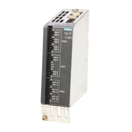
Page 37: Description Of Ports
Terminal Module TM17 High Feature 3.3 Description of Ports Description of Ports 3.3.1 Overview Figure 3-1 TM17 High Feature interface description TM15 / TM17 High Feature Terminal Modules Manual, 11/2016... -
Page 38: Sample Connection
Terminal Module TM17 High Feature 3.3 Description of Ports 3.3.2 Sample connection TM15 / TM17 High Feature Terminal Modules Manual, 11/2016... - Page 39 Terminal Module TM17 High Feature 3.3 Description of Ports Figure 3-2 TM17 High Feature connection example TM15 / TM17 High Feature Terminal Modules Manual, 11/2016...
-
Page 40: X500 And X501 Drive-Cliq Interface
Terminal Module TM17 High Feature 3.3 Description of Ports 3.3.3 X500 and X501 DRIVE-CLiQ interface Table 3-2 DRIVE-CLiQ interface X500 and X501 Signal name Technical specifications Transmit data + Transmit data - Receive data + Reserved, do not use Reserved, do not use Receive data - Reserved, do not use Reserved, do not use... - Page 41 Terminal Module TM17 High Feature 3.3 Description of Ports Note The two "+" and "M" terminals are jumpered in the connector and not in the device. This ensures that the supply voltage is looped through. The current consumption increases by the value for the DRIVE-CLiQ node. The digital outputs are supplied via terminals X520, X521, and X522.
-
Page 42: X520 Digital Inputs/Outputs
Terminal Module TM17 High Feature 3.3 Description of Ports 3.3.5 X520 digital inputs/outputs Table 3-5 Screw terminal X520 Terminal Designation Technical specifications M (GND) See chapter "Technical specifications" DI/O 0 DI/O 1 M (GND) DI/O 2 DI/O 3 M (GND) DI/O 4 DI/O 5 M (GND) -
Page 43: X522 Digital Inputs/Outputs
Terminal Module TM17 High Feature 3.3 Description of Ports L1+: A 24 VDC infeed for DI/O 0 to 7 (first voltage group) must always be connected when at least one DI/O of the voltage group is used as an output. L2+: A 24 VDC infeed for DI/O 8 to 15 (second potential group) must always be connected when at least one DI/O of the potential group is used as an output. -
Page 44: Description Of The Leds On Terminal Module Tm17 High Feature
Terminal Module TM17 High Feature 3.3 Description of Ports 3.3.8 Description of the LEDs on Terminal Module TM17 High Feature Table 3-8 Description of the LED Color State Description Electronics power supply outside permissible tolerance range. Green Continuous The component is ready for operation and cyclic DRIVE-CLiQ com‐ munication is taking place. -
Page 45: Dimension Drawing
Terminal Module TM17 High Feature 3.4 Dimension drawing Dimension drawing Figure 3-3 Dimension drawing of TM17 High Feature (like TM15) TM15 / TM17 High Feature Terminal Modules Manual, 11/2016... -
Page 46: Installation
Terminal Module TM17 High Feature 3.5 Installation Installation Installation 1. Place the component on the DIN rail. 2. Snap the component on to the DIN rail. Make sure that the mounting slides at the rear latch into place. 3. You can now move the component on the DIN rail to the left or to the right to its final position. Disassembly Figure 3-4 Releasing the component from a DIN rail... -
Page 47: Electrical Connection
Terminal Module TM17 High Feature 3.6 Electrical Connection Electrical Connection It is always advisable to shield the digital input/output wiring. The following pictures show two typical shield connections from Weidmüller. Weidmüller PE terminal Article No. KLBÜ CO 1 M4 / 1.8 Nm Figure 3-5 Shield connections Company Internet addresses:... - Page 48 3.6 Electrical Connection Connector coding Siemens supplies a series of coding elements (coding sliders) with each Terminal Module TM17 High Feature. To code a connector, you must insert at least one coding slider and cut off at least one coding projection on the connector:...
-
Page 49: Commissioning
Terminal Module TM17 High Feature 3.7 Commissioning Commissioning Note SIMOTION Terminal Modules TM15 / TM17 For information about commissioning , see the High Feature Commissioning Manual. TM15 / TM17 High Feature Terminal Modules Manual, 11/2016... -
Page 50: Technical Data
Terminal Module TM17 High Feature 3.8 Technical data Technical data Table 3-9 Technical data Terminal Module TM17 High Feature Unit Value Electronic power supply Voltage 24 VDC (20.4 – 28.8) Current (without DRIVE-CLiQ or digital outputs) Power loss <4 Ambient temperature up to an altitude of 2000 m °C 0 - 60 Storage temperature... - Page 51 Terminal Module TM17 High Feature 3.8 Technical data Terminal Module TM17 High Feature Unit Value ● Leakage current in OFF state μA max. 10 per channel ● Output voltage drop (I/O power supply to the output) ● Max. total current of the outputs (per group) to 60 °C to 50 °C to 40 °C...
- Page 52 Terminal Module TM17 High Feature 3.8 Technical data TM15 / TM17 High Feature Terminal Modules Manual, 11/2016...
-
Page 53: Standards, Certificates And Approvals
This device can be used in all areas except residential areas. Declaration of conformity The current Declaration of conformity is available on the Internet at Declaration of conformity. See also Declaration of conformity (http://support.automation.siemens.com/WW/view/en/ 10805446/134200) TM15 / TM17 High Feature Terminal Modules Manual, 11/2016... - Page 54 Standards, Certificates and Approvals TM15 / TM17 High Feature Terminal Modules Manual, 11/2016...
-
Page 55: Esd Guidelines
ESD guidelines ESD definition What does ESD mean? Electrostatic sensitive devices (ESDs) are individual components, integrated circuits, modules or devices that may be damaged by either electrostatic fields or electrostatic discharge. NOTICE Damage caused by electric fields or electrostatic discharge Electric fields or electrostatic discharge can result in malfunctions as a result of damaged individual parts, integrated circuits, modules or devices. -
Page 56: Electrostatic Charging Of Individuals
ESD guidelines B.2 Electrostatic charging of individuals Electrostatic charging of individuals Any person who is not conductively connected to the electrical potential of the environment can accumulate an electrostatic charge. This figure indicates the maximum electrostatic charges that can accumulate on an operator when he comes into contact with the indicated materials. -
Page 57: Basic Measures For Protection Against Discharge Of Static Electricity
ESD guidelines B.3 Basic measures for protection against discharge of static electricity Basic measures for protection against discharge of static electricity Ensure sufficient grounding When working with electrostatic sensitive devices, make sure that the you, your workstation, and the packaging are properly grounded. This prevents the accumulation of static electricity. Avoid direct contact You should only touch ESD components if unavoidable (for example, during maintenance work). - Page 58 ESD guidelines B.3 Basic measures for protection against discharge of static electricity TM15 / TM17 High Feature Terminal Modules Manual, 11/2016...
-
Page 59: Index
Index Interface descriptions Terminal Module TM15, 21 CE marking, 53 Components Terminal Module TM15, 19 Length of cable Terminal Module TM17 High Feature, 35 Voltage supply , 24, 41 cULus approval, 53 Current in OFF state - input, 33, 50 Max. - Page 60 Index UL certification, 53 Voltage drop - output, 34, 51 Voltage drop in the ON state - output, 33, 50 Voltage supply Length of cable, 24, 41 TM15 / TM17 High Feature Terminal Modules Manual, 11/2016...